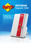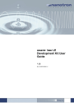
1
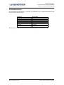
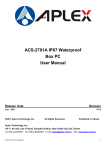
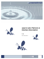
Test Specification
Test Procedure for Nanotron Sensor Modules
Version Number: 2.10 Author: Thomas Reschke
swarm radio Platform &
Interface Description
1.0
NA-13-0267-0002-1.0
Hardware Description
swarm radio Platform & Interface Description
Version: 1.0 Author: Dr. Frank Schlichting
Document Information
Document Title:
swarm radio Platform & Interface Description
Document Version:
1.0
Current Date:
2013-02-21
Print Date:
2013-02-21
Document ID:
NA-13-0267-0002-1.0
Document Author:
Dr. Frank Schlichting
Disclaimer
Nanotron Technologies GmbH believes the information contained herein is correct and accurate at the time of release. Nanotron
Technologies GmbH reserves the right to make changes without further notice to the product to improve reliability, function or
design. Nanotron Technologies GmbH does not assume any liability or responsibility arising out of this product, as well as any
application or circuits described herein, neither does it convey any license under its patent rights.
As far as possible, significant changes to product specifications and functionality will be provided in product specific Errata sheets,
or in new versions of this document. Customers are encouraged to check the Nanotron website for the most recent updates on
products.
Trademarks
All trademarks, registered trademarks, and product names are the sole property of their respective owners.
This document and the information contained herein is the subject of copyright and intellectual property rights under international
convention. All rights reserved. No part of this document may be reproduced, stored in a retrieval system, or transmitted in any form
by any means, electronic, mechanical or optical, in whole or in part, without the prior written permission of Nanotron Technologies
GmbH.
Copyright © 2013 Nanotron Technologies GmbH.
Page 2 Doc ID NA-13-0267-0002-1.0
© 2013 All Rights Reserved
Hardware Description
swarm radio Platform & Interface Description
Version: 1.0 Author: Dr. Frank Schlichting
Contents
1. Scope........................................................................................................................................................ 4
2. Hardware Platform & Interface to Host ..................................................................................................... 5
2.1. Embedded platform ........................................................................................................................... 5
2.2. Interface to host.................................................................................................................................. 7
2.3. LED / Push button - User Interface..................................................................................................... 8
3. Revision History ........................................................................................................................................ 9
© 2013 All Rights Reserved
Doc ID: NA-13-0267-0002-1.0 Page 3
Hardware Description
swarm radio Platform & Interface Description
Version: 1.0 Author: Dr. Frank Schlichting
1. Scope
Scope of this document is to describe the embedded swarm radio hardware platform and its physical
interface to the host controller. The swarm radio is accessed by a host platform via a hardware
independent Application Programming Interface (API) which is described in a separate swarm API
document. A swarm is defined as a congregation of independent radios or nodes which share a common
interest in their relative positioning and communication towards each other for a certain period of time.
Page 4 Doc ID NA-13-0267-0002-1.0
© 2013 All Rights Reserved
Hardware Description
swarm radio Platform & Interface Description
Version: 1.0 Author: Dr. Frank Schlichting
2. Hardware Platform & Interface to Host
2.1. Embedded platform
The following general software requirements have to be met for implementing the embedded software
code for elementary ranging functionality:
In order to realize the customer’s application requirements and keep the development time to a minimum
an existing Nanotron embedded hardware platform has been selected: nanoPAN 5375 DK board with the
following specifications
Parameter
Output power
Antenna diversity
Number of antennas
Available interfaces
Indicators
Keys
Voltage supply
Maximum current drain
Microcontroller
Flash
RAM
EEPROM
RF Transceiver Chip
Modulation
Specification
+ 20dBm = 100mW
no
1
UART via USB
6 LEDs
3 Keys
5V USB or 2.8 … 4.0V battery pack
< 500 mA
ATMEL ATMega 1284P
128 kB
16 kB
4 kB
nanoLOC TRX
Chirp Spread Spectrum (CSS)
Tab. 1: swarm radio technical data
Fig. 2: swarm radio based on nanoPAN 5375 DK Board
© 2013 All Rights Reserved
Doc ID: NA-13-0267-0002-1.0 Page 5
Hardware Description
swarm radio Platform & Interface Description
Version: 1.0 Author: Dr. Frank Schlichting
For the desired customer application set-up a set of minimum two swarm nodes are required. Each Unit
possesses a unique node ID, which is used to address the ranging partner for the elementary peer to peer
ranging operation.
The swarm nodes interact with their respective host platforms via their serial interface, e.g. virtual COM via
USB or UART port.
Page 6 Doc ID NA-13-0267-0002-1.0
© 2013 All Rights Reserved
Hardware Description
swarm radio Platform & Interface Description
Version: 1.0 Author: Dr. Frank Schlichting
2.2. Interface to host
The embedded swarm radio platform is connected to its individual host by a standard virtual COM via USB
interface with the following settings:
Parameter
Interface type
Flow control
Data bits
Stop bits
Available interfaces
Parity
Data rate
Data flow
Specification
Virtual COM via USB
off
8
1
1
None
115,2 kbps
bidirectional
Tab. 2: Interface specifications between host & embedded platform for virtual COM via USB
© 2013 All Rights Reserved
Doc ID: NA-13-0267-0002-1.0 Page 7
Hardware Description
swarm radio Platform & Interface Description
Version: 1.0 Author: Dr. Frank Schlichting
2.3. LED / Push button - User Interface
The LEDs available on the swarm radio node will be used as live tick and status indicators as follows:
Fig. 3: Location and numbering of the swarm radio node buttons and indicator LEDs
LED1:
Function:
Interval:
Node “alive” tick: indicates proper voltage supply and embedded SW running
1 Hz blink: 200ms on, 800 ms off
Function:
Interval:
Indicating successful elementary ranging cycle successful (Errorcode = 0
On for 100ms
Function:
Interval:
Indicating ranging request from another node
On for 100ms when request received
Function:
Interval:
Indicating ranging error or parameter overflow occurred
On for 100ms
Function:
Status:
Indicating active / passive / sniffer mode of operation
On for active (default), Off for passive, Blinking for sniffer (on/off: 200ms/800ms)
Function:
Status:
Indicating ID broadcast mode on/off
On for ID broadcast enabled (default), Off for ID broadcast disabled
Function:
Toggle active/passive mode
Function:
Toggle sniffer mode
Function:
Toggle ID broadcast mode on/off
LED2:
LED3:
LED4:
LED5:
LED6:
KEY 1:
KEY 2:
KEY 3:
Page 8 Doc ID NA-13-0267-0002-1.0
© 2013 All Rights Reserved
Hardware Description
swarm radio Platform & Interface Description
Version: 1.0 Author: Dr. Frank Schlichting
3. Revision History
Date
2013-02-21
Authors
F. Schlichting
Version
1.0
Description
Initial version, extracted from swarm API
specification document
End of Document
© 2013 All Rights Reserved
Doc ID: NA-13-0267-0002-1.0 Page 9
Hardware Description
swarm radio Platform & Interface Description
Version: 1.0 Author: Dr. Frank Schlichting
Life Support Policy
These products are not designed for use in life support
appliances, devices, or systems where malfunction of these
products can reasonably be expected to result in personal
injury. Nanotron Technologies GmbH customers using or
selling these products for use in such applications do so at
their own risk and agree to fully indemnify Nanotron
Technologies GmbH for any damages resulting from such
improper use or sale.
Electromagnetic Interference / Compatibility
Nearly every electronic device is susceptible to
electromagnetic interference (EMI) if inadequately shielded,
designed, or otherwise configured for electromagnetic
compatibility. To avoid electromagnetic interference and/or
compatibility conflicts, do not use this device in any facility
where posted notices instruct you to do so. In aircraft, use of
any radio frequency devices must be in accordance with
applicable regulations. Hospitals or health care facilities may
be using equipment that is sensitive to external RF energy.
With medical devices, maintain a minimum separation of 15
cm (6 inches) between pacemakers and wireless devices and
some wireless radios may interfere with some hearing aids. If
other personal medical devices are being used in the vicinity of
wireless devices, ensure that the device has been adequately
shielded from RF energy. In a domestic environment this
product may cause radio interference in which case the user
may be required to take adequate measures.
CAUTION - Electrostatic Sensitive Device! Precaution
should be used when handling the device in order to prevent
permanent damage.
FCC User Information
Statement according to FCC part 15.19:
This device complies with Part 15 of the FCC Rules. Operation
is subject to the following two conditions: (1) this device may
not cause harmful interference, and (2) this device must
accept any interference received, including interference that
may cause undesired operation.
Statement according to FCC part 15.21:
Modifications not expressly approved by this company could
void the user's authority to operate the equipment.
RF exposure:
The internal / external antennas used for this mobile
transmitter must provide a separation distance of at least 20
cm from all persons and must not be co-located or operating in
conjunction with any other antenna or transmitter.
Statement according to FCC part 15.105:
This equipment has been tested and found to comply with the
limits for a Class A and Class B digital device, pursuant to Part
15 of the FCC Rules. These limits are designed to provide
reasonable protection against harmful interference in a resi-
dential installation and against harmful interference when the
equipment is operated in a commercial environment.
This equipment generates, uses, and can radiate radio frequency energy and, if not installed and used in accordance
with the instructions as provided in the user manual, may
cause harmful interference to radio communications. However,
there is no guarantee that interference will not occur in a
particular installation. Operation of this equipment in a residential area is likely to cause harmful interference in which
case the user will be required to correct the interference at his
or her own expense.
If this equipment does cause harmful interference to radio or
television reception, which can be determined by turning the
equipment off and on, the user is encouraged to try to correct
the interference by one or more of the following measures: (1)
reorient or relocate the receiving antenna, (2) increase the
separation between the equipment and receiver, (3) connect
the equipment into an outlet on a circuit different from that to
the connected equipment, and (4) consult the dealer or an
experienced technician for help.
About Nanotron Technologies GmbH
Nanotron provides reliable loss protection
technology and solutions that are used to protect
people and animals. Energy efficient, batterypowered wireless nodes are the key building
blocks. These small devices create a Virtual
Safety Zone which protects tagged people and
animals. Robust wireless Chirp technology
underpins nanotron’s offering of chips, modules
and loss protection software for indoor and
outdoor environments world wide.
Page 10 Doc ID NA-13-0267-0002-1.0
Headquartered in Berlin, Germany, Nanotron Technologies
GmbH was founded in 1991.
Further Information
For more information about products from Nanotron
Technologies GmbH, contact a sales representative at the
following address:
Nanotron Technologies GmbH
Alt-Moabit 60
10555 Berlin, Germany
Phone: +49 30 399 954 – 0
Fax: +49 30 399 954 – 188
Email: [email protected]
Internet: www.nanotron.com
© 2013 All Rights Reserved