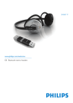
1
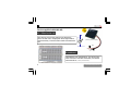
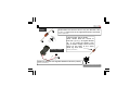
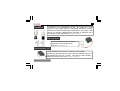
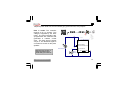
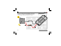
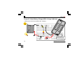
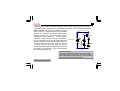
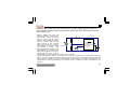
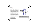
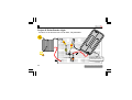
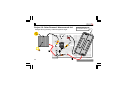
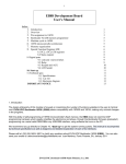
Required parts: Solar cell, microcontroller (µC), 2x 4K7 resistor (yellow, purple, red,
gold), 470 ohm resistor (yellow, purple, brown, gold), 2V4 zener diode, piezo sounder,
wire jumpers, wire.
7
VSS
+
VDD
2
How it works: The solar cell
IC1
R3
provides the supply voltage for the
PIC10F220
microcontroller. Once it receives
470
R1
2VDC it starts running its internal
4K7
program. The zener diode and the
470 ohm resistor make sure the
8
GP3/MCLR/VPP
5
supply voltage of the controller
GP0/ICSPDAT
3
GP2/T0CLKI/FOSC4
never goes beyond 2.4V, even in
ZD1
4
GP1/ICSPCLK
bright sunlight. A too high voltage SOLAR CELL
R2
2V4
4K7
BUZ1
can damage the device.
The
PIEZO
voltage generated by the solar cell is
also divided by two by means of two
equal resistors (4K7) and fed to the
analog input of the PIC. Even in
bright sunlight, the input receives no more than 4.5/2 = 2.25VDC.
The internal software ‘measures’ the voltage at the input and translates it to a variable audio frequency
(note). The piezo sounder converts the signal into sound. When the amount of light received by the solar
cell changes, the voltage at the input of the controller will also change. The sofware will notice this and
change the tone. With a bit of practice, you could play a tune by waving your hand or a flashlight over the
solar cell.
www.vellemanprojects.com
19