1
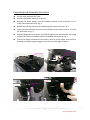
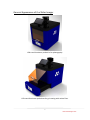
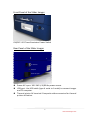
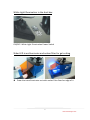
Slider Imager Instruction Manual Catalog Number SML‐01 Version 01_10 1 www.maestrogen.com Hardware Instruction Manual This Slider Imager is suitable for research use only. It must be used by specialized personnel that know the health risks associated with blue light irradiation and with the reagents that are normally used with this instrument. Human naked eyes with long time irradiation of blue light may have the probability of suffering from retina diseases. The amber filter provides blue light protection and is used for gel cutting. However, it does not guarantee complete protection. It is designed to shield the person working at the Slider Imager only. WARRANTY The Slider Imager is warranted against defects in materials and workmanship for 1 year. If any defects occur in the instrument or accessories during this warranty period, Maestrogen will repair or replace the defective parts at its discretion without charge. The following defects, however, are specifically excluded: 1. Defects caused by improper operation. 2. Repair or modification done by anyone other than Maestrogen or an authorized agent. 3. Damage caused by substituting alternative parts. 4. Use of fittings or spare parts supplied by anyone other than Maestrogen. 5. Damage caused by accident or misuse. 6. Damage caused by disaster. 7. Corrosion caused by improper solvent or sample. For any inquiry or request for repair service, please contact your local Maestrogen office and inform Maestrogen of the model and serial number of your instrument. REGULATORY NOTICE IMPORTANT: This Maestrogen instrument is designed and certified to meet safety standards and EMC regulations. Certified products are safe to use when operated in accordance with the instruction manual. This instrument should not be modified or altered in any way. Alteration of this instrument will: 1. Void the manufacturer’s warranty 2. Void the safety and EMC certification 3. Create a potential safety hazard 2 www.maestrogen.com Maestrogen is not responsible for any injury or damage caused by the use of this instrument for purposes other than those for which it is intended, or by modifications of the instrument not performed by Maestrogen or an authorized agent. IMPORTANT NOTICE Please, read the installation instruction carefully before installing the Slider Imager. This instrument is intended for clinical and research laboratory use with DNA gel activation and it must be operated only by specialized personnel aware of the potential risks associated with the chemical and biological agents normally used with this unit. This instrument is meant for use only by specialized personnel that know the health risks associated with blue light radiation and with reagents that are normally used with this instrument. The amber filter provides some blue light protection. However, it does not guarantee complete protection, and it is designed to shield only the person working in front of the system, also to observe the DNA gel fluorescence emission clearly and perform gel cutting. 3 www.maestrogen.com SPECIFICATIONS 1. Outline Dimensions (mm): 385 (W) x 415(D) x 455(H) 2. Weight: approx. 20 kg 3. Rated Voltage: 100V~240V/ Fuse: 1.25A 4. Filter: Amber filter 5. Trans‐illumination: LED (470 nm) 6. Viewing Size (mm): 160 x 200 (Same as UltraBright LED transilluminator LB‐16) 7. Gel cutting filter: Amber filter 8. LCD: 7“‐Wide TFT‐LCD (1) Display Area (mm):180.72(H) x 94.27(V) (2) Number of Pixels:480(H) x 3(RGB) x 220(V) (3) Aspect ratio:16:9 (4) Brightness (nits):250 (Typ.) (5) Contrast Ratio:500:1 (Typ.) (6) Blacklight Unit:LED (7) Surface Treatment:Anti‐Glare 9. Digital camera: (1) Effective pixel:12.2 M (2) Lens: Fujinon 15x lens, F3.1 (Wide) ‐ F5.6 (Telephoto) (3) Mode: Program (P), Aperture Priority (A), Shutter Priority (S), Manual (M) (4) ISO:Auto/100/200/400/800/1600/3200/6400 (5) Video Output: NTSC / PAL selectable (6) Storage Media: SD/SDHC memory card (7) Storage Format: JPEG (ExifVer 2.2) 10. LCD monitor rotation: 0~90 degree 11. USB port: connect Slider and PC via USB cable 12. AV terminal: thermal printer accessory compatible INSTALLATION Carefully unpack the Slider Imager as follows: 1. First remove the bubble material at the top. 2. Remove the Slider Imager from the bubble material shells and place it on a stable, horizontal surface. 3. Remove the plastic protection film from the transparent glass viewing surface and the amber filter. 4 www.maestrogen.com Stand alone installation: 1. The instrument must be placed on a bench leaving at least 10 cm of space all around in order to avoid any obstacle that may reduce the ventilation. 2. Connect the instrument to the power using the annexed cable. The power font must be able to deliver at least 250 VA with a voltage between 100 and 240 Vac. The plug must have a ground connection. GENERAL PRECAUTIONS ∙ Plug the imager on an electric line with ground connection. ∙ The imager is equipped with thermal protection to prevent overheating. ∙ Do not pour liquids directly on the imager. ∙ Do not punch or collide the imager. ∙ Switch off the instrument immediately after its use. ∙ Position the imager to prevent harm to nearby operators. ∙ The imager sample surface is a glass sheet for cutting gels. When using the imager with samples stained with specific dyes, decontaminate the glass surface with bleach. Denatured alcohol can be also used. Always wear disposable gloves. Using the imager Place gel/sample on the transparent glass support area. It is recommended that gloves be worn to prevent skin contact with gel and staining agents. Press the ON/OFF switch to ON. The LEDs within the unit will begin glowing under the glass support. After taking photographs of the sample or cutting out of the bands, turn the imager off. 5 www.maestrogen.com Unpacking and Assembly Instruction Cut the tape and open the case. Remove the bubble material at the top. Remove the Slider Imager from the bubble material shells and place it on a stable, horizontal surface as Fig. 1. Rotate the LCD adjustment to a suitable angle for observation as Fig. 2. Place the camera fixation screw into the sidewall of the camera mount, 2 screws for both sides as Fig. 3. Use M2 Hexagonal screw driver to SLIGHTLY tighten the camera when the image on the LCD screen is exhibited with an acceptable horizontal as Fig. 4. To test the image horizontal of the camera, place a card or paper with words or drawings on the gel supporting glass and turn on white light to adjust. LCD Monitor Rotation Adjustment Camera Mount Fig. 1 Fig. 2 Camera Fixation Screw Fig. 4 Fig. 3 6 www.maestrogen.com General Appearance of the Slider Imager LED transilluminator pushed‐in for photography LED transilluminator pulled‐out for gel cutting with amber filter 7 www.maestrogen.com Front Panel of the Slider Imager ON/OFF: LED Transilluminator Power Switch Rear Panel of the Slider Imager AV terminal USB port Power AC input Power AC input: 100~240 V; 50/60 Hz power source. USB port: Use USB cable (type A male to A male) to connect imager and PC computer. Thermal printer AV terminal: Composite video connector for thermal printer utilization. 8 www.maestrogen.com White Light Illumination in the dark box ON/OFF: White Light Illumination Power Switch Slider LED transilluminator and amber filter for gel cutting Draw the transilluminator out with amber filter fixed on edge of it 9 www.maestrogen.com LCD monitor and camera LCD monitor: ON/OFF button mainly used. Slider LCD Operating Instructions Button Function Down :Positive and Negative Adjustment Menu :Activation of Menu Indicator UP :Positive and Negative Adjustment POWER:ON / OFF / Mode Selection and Enter button in function menu mode (OFF Press and hold for about 3 seconds to turn off the power) Display Area Power OFF Down button Menu button Up button Power button Press Power ON Mode Selection When monitor is power on, press ” V1 mode ” button to change mode between V1 and V2. The real-time display from digital camera Press Press & Hold 3 sec. V2 mode Adjust Button (the button will work when the monitor is in function menu mode ) is in one of the two channels. Press and hold the ” ” button for 3 seconds, the monitor power will be turned off. Press adjust ( / ) button to adjust the basic function, reset all function, and choose NTSC/PAL mode in V1 or V2 mode. 10 www.maestrogen.com Camera: Auto‐focus, exposure time or shutter manually or automatically controlled. If it is needed to zoom in, scroll the zoom in shown on LCD screen. This bar up to ruler scale as helps the camera contain the full viewing surface of transilluminator and gets the best image contrast. Back Side Application NOTICE AC power input: Plug AC power cord and turn on the safety switch ON for utilization of Slider. USB port: There are two ways to access the digital image file in the camera. 1). Take out memory card in camera and read files with a card reader. 2). Use USB cable (type A male to A male) to connect Slider USB port and PC. The digital files in the camera will be automatically read by PC. AV terminal: ‐ Terminal jack and switch for accessory of thermal printer. With thermal printer connected with the AV terminal, please turn switch ON for printing. ‐ When printer is not in use, please turn switch OFF. ‐ Without thermal printer connected with the AV terminal, please turn switch OFF for LCD normal display. 11 www.maestrogen.com TECHNICAL SUPPORT Maestrogen offers technical support for all of its products. If you have any questions about the product’s use or, operation, please contact Maestrogen at the following info. 8275 South Eastern, Avenue #200, LAS VEGAS NV 89123, USA E‐Mail: [email protected] 12 www.maestrogen.com