1
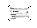
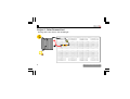
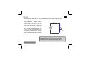
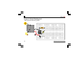
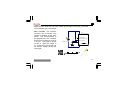
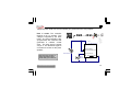
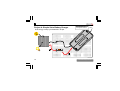
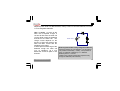
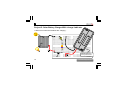
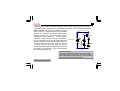
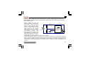
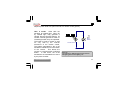
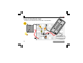
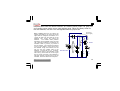
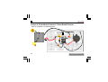
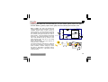
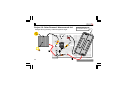
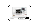
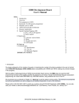
E D U 02
Solar Energy Experiment Kit
Nederlands
Français
Deutsch
Espagnol
Italiano
www.velleman.eu
AGE
12+
VELLEMAN NV
Legen Heirweg 33
9890 Gavere
Belgium Europe
www.velleman.be
www.velleman-kit.com
10 exciting solar projects which you can actually use.
Projects featured in this box:
Solar-Powered LED ...........................................................................As long as the sun shines, the LED will light (pag.8)
Flashing Solar LED ............................................................................................Solar-powered attention grabber (pag.10)
Solar-Powered Cricket......................................... ......................As long as the sun shines, the cricket will chirp (pag.12)
Simple Solar Battery Charger .................................. ..................... Free energy to keep your batteries in shape (pag.14)
Solar Battery Charger with ‘Charge’ Indicator................... An LED turns on when the batteries are charging (pag.16)
Solar Musical Instrument.................................................................. ............................. More light = higher note (pag.18)
IR Remote Control Tester............................................................... ............................ ‘Listen’ to your IR remote (pag.20)
Solar Garden Light............................... ................... LED turns on at dusk and turns off at dawn, fully automatic (pag.22)
Solar Motion Detector / Beam Break Detector .............. ................... Announce wanted or unwanted guests (pag.24)
Solar-Powered ‘Alarm Armed’ LED................... ................... Charges during the day, scares burglars at night (pag.26)
Attention: All projects require direct sunlight or a strong incandescent lightbulb (min 60W). Fluorescent, energy saving, led
and certain halogen lightsources are not suited or will not give satisfactory results.
www.vellemanprojects.com
3
Parts supplied with this kit:
4V / 30mA solar cell
This device will convert sunlight into electricity,
which we will use in all projects. More light means
more electricity. Point the black surface towards the
sun.
E1
(Velleman part# YH-39X35)
SOLAR CELL
Red
B la
ck
Breadboard
Will hold all your experiments. The white lines
show how the holes are electrically connected
with eachother (Velleman part# SDAD102)
4
www.vellemanprojects.com
Ultrabright yellow & red LED
Flat side
Shortest leg = (-)
Wire jumper
Just a piece of bare wire to
connect two points in a circuit.
The yellow & red LED provide a lot of light and require a very low
current to operate. Watch the polarity ! (Velleman part# L-5YAC & L-7104LID)
Resistors
R1
100
www.vellemanprojects.com
Various resistor values are supplied. They serve as
current limiters or as voltage dividers. Resistors do
not have a polarity. Resistors values are indicated
by means of coloured rings. The unit of resistance is
called ’Ohm’.
5
Diode
Diodes allow the current to flow in only one direction, from
(+) to (–). Current flow in the opposite direction is blocked.
(Velleman part# BAT85)
Battery holder
A special case: Zener diodes
Zener diodes allow the current to
flow from (+) to (-), as regular diodes
do. If you invert the polarity, they
drop a certain voltage, which can be
found on the body of the zener
diode, e.g. 2V4= 2.4V
(Velleman part# ZA2V4)
d
Re
B la
ck
Holder for two AAA rechargeable batteries. Mind the polarity
(Velleman part# BH421A)
6
www.vellemanprojects.com
Transistors
E
B C
C B E
A transistor is an amplification device. By means of a small
current, a much larger current is controlled. Transistors come in
two flavours, NPN and PNP-types, depending on the polarity. With
this kit, you receive a BC557 (PNP) transistor. A transistor has 3
pins: Base, Emitter and Collector. (Velleman part# BC557B)
Piezo speaker
A piezo speaker converts an electric
signal into sound. Polarity is not
important (Velleman part# TV1)
Microcontroller (µC)
Noir
Rouge
A programmable device which can perform various tasks.
We have pre-programmed it so that it will play musical notes or it
will generate the sound of a cricket. This device is has a polarity.
Watch the position of the notch. (Velleman part# VKEDU02)
www.vellemanprojects.com
7
Project 1: Solar Powered Led
As long as the sun shines, the led will light...
8
www.vellemanprojects.com
Required parts: Solar cell, 100 ohm resistor (brown black brown gold), yellow led
How it works: A closed circuit is
required to make the current flow.
Current flows from the (+) of the
solar cell trough resistor to the (+)
of the led and via the (-) of the led
back to the solar cell. On a sunny
day, the solar cell will generate 3..4
volts. The led only requires 2 volts
to operate. Resistor R1 converts
the excess voltage into (a little)
heat, hereby protecting the led from
damage.
R1
100
E1
SOLAR CELL
LD1
or ange
Time to experiment:
What happens when you swap (+) and (-) of the led?
What happens when you replace the 100 ohm resistor with
a 47000 ohm resistor (yellow purple orange gold) ?
www.vellemanprojects.com
9
Project 2: Solar Flashing Led
Solar powered attention grabber
µC
Jumper wire
10
www.vellemanprojects.com
Required parts: Solar cell, 100 ohm resistor (brown black brown gold), yellow led,
microcontroller (µC), wire jumper.
IC1
PIC10F200-I/PG
VDD
2
How it works: The controller
requires 2-5V to operate. This
voltage is supplied by the solar
panel. The microcontroller is
pre-programmed with software
that turns the output on and off
in a loop. The signal is output
via pin 4. When the output is
on, current flows via the led and
the resistor, hereby causing the
led to light.
R1
SOLAR CELL
100
4
GP0/ICSPDAT
GP2/T0CLKI/FOSC4
GP1/ICSPCLK
VSS
5
3
GP3/MCLR/VPP
8
7
LD1
µC
www.vellemanprojects.com
11
Project 3: Solar Powered Cricket
As long as the sun shines, the circket will chirp...
Jumper wire
µC
Jumper wire
12
www.vellemanprojects.com
Required parts: Solar cell, microcontroller (µC), piezo sounder, wire jumpers
4
GP1/ICSPCLK
GP3/MCLR/VPP
8
7
BUZ1
PIEZO
GP0/ICSPDAT
GP2/T0CLKI/FOSC4
VSS
5
3
SOLAR CELL
Hint: Use this circuit as a
wake-up-at-dawn alarm.
It will wake you at sunrise...
IC1
PIC10F200-I/PG
VDD
2
µC
+
How it works: The controller
requires 2-5V to operate. This
voltage is supplied by the solar
panel. The microcontroller is pre
-programmed with software that
generates a realistic cricket
chirp. The chirp signal is output
via pin 4. The electrical signal is
converted to sound via the piezo
speaker.
www.vellemanprojects.com
13
Project 4: Simple Solar Battery Charger
Insert two AAA 1.2V
rechargeable batteries*
Free energy to keep your batteries in shape...
*Not included
14
www.vellemanprojects.com
Required parts: Solar cell, BAT85 diode, battery holder for two AAA batteries, two AAA
1.2V rechargeable batteries.
How it works: As long as the
solar cell is exposed to light, a
current will flow from the solar cell
via the diode trough the batteries
and back to the solar cell. The
charge current depends on the
amount of light that reaches the
solar cell. Max. current with the
supplied cell is 30mA.
A diode prevents discharge of the
batteries trough the solar cell
(e.g. at nighttime), as it only
allows the current to pass in one
direction.
www.vellemanprojects.com
BAT85
SOLAR CELL
How long does it take to fully charge the batteries?
Check the capacity of your batteries. You can find this
info printed on the battery. Usually, it is expressed in
mAh, e.g. 300mAh. Multiply by 1.2 = 360mAh.
Divide by 30mA = 12 hours
Twelve hours of bright sunlight are required to fully
charge the batteries (rule of thumb).
15
Project 5: Solar Battery Charger With ‘charge’-Indicator
A led turns on when the batteries are charging...
Insert two AAA 1.2V
rechargeable batteries*
*Not included
16
www.vellemanprojects.com
Required parts: Solar cell, BC557 transistor, 4K7 resistor (yellow, purple, red, gold),
yellow led, battery holder for two AAA batteries, two AAA 1.2V rechargeable batteries.
How it works: When the sun shines, a current
flows from the (+) of the solar cell via the Emitter/
Base of the transistor trough the batteries and
BC557
back to the solar cell. This is the Base current,
indicated with the dotted line. In our example,
the Base current will also charge our batteries.
The fact that there is a current flowing between SOLAR CELL
4K7
Emitter and Base causes the transistor to turn on
and fully conduct, as if it were a switch. Hence,
or ange le
a current can flow from the solar cell via the
transistor Emitter/Collector and resistor to the led
and back to the solar cell. This current causes
the led to light (solid line).
For advanced users:
The led turns off when the batteries are removed. Why ?
In the simple battery charge circuit, there was a diode to
prevent discharging of the batteries in low light condition.
In this circuit, it has been omitted. Why ?
www.vellemanprojects.com
17
Project 6: Solar Musical Instrument
More light = higher note
Wire
Jumper wire
4K7
4K7
µC
PIC
470
18
www.vellemanprojects.com
Required parts: Solar cell, microcontroller (µC), 2x 4K7 resistor (yellow, purple, red,
gold), 470 ohm resistor (yellow, purple, brown, gold), 2V4 zener diode, piezo sounder,
wire jumpers, wire.
7
VSS
+
VDD
2
How it works: The solar cell
IC1
R3
provides the supply voltage for the
PIC10F220
microcontroller. Once it receives
470
R1
2VDC it starts running its internal
4K7
program. The zener diode and the
470 ohm resistor make sure the
8
GP3/MCLR/VPP
5
supply voltage of the controller
GP0/ICSPDAT
3
GP2/T0CLKI/FOSC4
never goes beyond 2.4V, even in
ZD1
4
GP1/ICSPCLK
bright sunlight. A too high voltage SOLAR CELL
R2
2V4
4K7
BUZ1
can damage the device.
The
PIEZO
voltage generated by the solar cell is
also divided by two by means of two
equal resistors (4K7) and fed to the
analog input of the PIC. Even in
bright sunlight, the input receives no more than 4.5/2 = 2.25VDC.
The internal software ‘measures’ the voltage at the input and translates it to a variable audio frequency
(note). The piezo sounder converts the signal into sound. When the amount of light received by the solar
cell changes, the voltage at the input of the controller will also change. The sofware will notice this and
change the tone. With a bit of practice, you could play a tune by waving your hand or a flashlight over the
solar cell.
www.vellemanprojects.com
19
Project 7: IR Remote Control Tester
‘Listen’ to your IR remote
PIC
+/- 5cm
20
www.vellemanprojects.com
How it works:
Solar cells are
sensitive to infrared light. When hit
by infrared light, they generate a
voltage, like they do with sunlight. IR
remote controls generate a beam of
infrared light when they are operated.
This beam of light is turned on and
off very fast by the internal
electronics of the remote control.
The pattern generated by the on-off
transitions is different for each button
of the remote.
This allows the
receiver to recognise each individual
button. In this circuit, the on-off
transistions are translated into sound
by the piezo sounder.
www.vellemanprojects.com
+
Required parts: Solar cell, piezo sounder, IR remote control (option).
BUZ1
PIEZO
SOLAR CELL
More fun:
Try ‘listening’ to different light sources such as
led lighting, fluorescent lighting, etc...
21
Project 8: Solar Garden Light
Led turns on at dusk and turns off at dawn, fully automatic
470
4K7
Jumper wire
Insert two AAA 1.2V
rechargeable batteries*
*Not included
22
www.vellemanprojects.com
Required parts: Solar cell, BC557 transistor, 4K7 resistor (yellow, purple, red, gold), 470
ohm resistor (yellow, purple, brown, gold), BAT85 diode, yellow led, battery holder for
two AAA batteries, two AAA 1.2V rechargeable batteries, jumper wire.
www.vellemanprojects.com
Led current
(only at night)
BAT85
SOLAR CELL
Base current (only at night)
D1
Charge current
How it works: When the sun shines, the
voltage generated by the solar cell will be
higher than the voltage of the batteries, so a
current will flow from the solar cell to the
batteries. This current will charge the
batteries.
The BAT85 diode prevents
discharging of the batteries trough the solar
cell in low light conditions. The base of the
transistor is tied to ground (-) by means of
the 4K7 resistor. This causes the transistor
to turn on and allows a current to flow from
the batteries trough the transistor, the led
and via 470 ohm resistor back to the
batteries. The led will turn on. However,
note that the base of the transistor is also
tied to the (+) of the solar cell, so as long as
the sun shines, the base of the transistor is
kept high enough to prevent turn-on of the
transistor, so the led remains off at daytime.
BC557
orange led
R1
4K7
R2
470
23
Project 9: Solar Motion Detector / Beam Break Detector
Announce wanted or unwanted guests
Jumper wire
4K7
4K7
µC
470
Wire
24
www.vellemanprojects.com
Required parts: Solar cell, microcontroller (µC), 2x 4K7 resistor (yellow, purple, red, gold),
470 ohm resistor, (yellow, purple, brown, gold), 2V4 zener diode, piezo sounder, wire.
www.vellemanprojects.com
VDD
470
SOLAR CELL
R2
4K7
4
BUZ1
PIEZO
GP3/MCLR/VPP
GP0/ICSPDAT
GP2/T0CLKI/FOSC4
GP1/ICSPCLK
VSS
5
8
3
ZD1
2V4
7
R1
4K7
IC1
PIC10F220
2
R3
+
How it works: The solar cell provides the
supply voltage for the microcontroller. Once the
controller receives 2VDC it starts running its
internal program. The zener diode and the 470
ohm resistor make sure the supply voltage of
the controller never goes beyond 2.4V, even in
bright sunlight. A too high voltage can damage
the device. The voltage generated by the solar
cell is also divided by two by means of two
equal resistors (4K7) and fed to the analog
input of the controller.
Even in bright sunlight, the input receives no
more than 4.5/2 = 2.25VDC.
The internal software ‘measures’ the voltage at
the input and compares it to the previous level.
When it detects a sudden change (i.e. When
the beam is interrupted or someone casts a
shadow on the solar cell ), it generates a sound
trough the piezo.
4
P
P
4
4
25
Project 10: Solar Powered ‘Alarm armed’-led
Charges during the day, scares burglars at night
Insert two AAA 1.2V
rechargeable batteries*
Jumper wire
4K7
PIC
Jumper wire
26
µC
100
*Not included
www.vellemanprojects.com
Required parts: Solar cell, microcontroller (µC), 4K7 resistor (yellow, purple, red, gold), 100
ohm resistor, (brown, black, brown, gold), BAT85 diode, BC557 transistor, battery holder for
two AAA batteries, two AAA 1.2V rechargeable batteries, wire jumpers, red led.
www.vellemanprojects.com
D1
BAT85
2
BC557
IC1
VDD
PIC10F200-I/PG
GP0/ICSPDAT
GP2/T0CLKI/FOSC4
R1
4K7
GP3/MCLR/VPP
VSS
GP1/ICSPCLK
8
5
3
4
R2
100
Red led
7
SOLAR CELL
How it works: When the sun shines, the
voltage generated by the solar cell will be
higher than the voltage of the batteries, so a
current will flow from the solar cell to the
batteries. This current will charge the
batteries.
The BAT85 diode prevents
discharging of the batteries trough the solar
cell in low light conditions. The base of the
transistor is tied to ground (-) by means of the
4K7 resistor. This causes the transistor to
turn on and supply power to the µcontroller.
The controller will behave identical to project
2, so the led will flash. However, note that the
base of the transistor is also tied to the (+) of
the solar cell, so as long as the sun shines,
the base of the transistor is kept high enough
to prevent turn-on of the transistor, so the led
remains off at daytime.
27
Modifications and typographical errors reserved
© Velleman nv.
HEDU02 - 2010 - ED1
VELLEMAN NV
Legen Heirweg 33, 9890 Gavere
Belgium - Europe
5 410329 438111