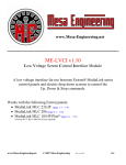
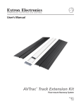
1
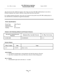
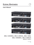
MLC 206 to Display Installation
/ Driver Designation: RS1.mll = RS232 Driver
IR.mll = IR Driver /
Connections and Documentation
MLC 206
Projector Communication Sheet
Read this document for additional assistance on wiring the MLC 206 to your display device. The
notes on the following page(s) are confirmed to work in the manner stated. Deviation on any
component(s) may require a different wiring scheme.
For complete operating instructions pertaining to the MLC 206, please refer to the MLC 206
user’s manual.
For complete operating instructions pertaining to the display device, please refer to the
display device user’s manual.
Projector Manufacturer: Dell
Projector Model: 4100MP
Projector Driver Name: Dell_4100MP_RS1.mll
Revision Date: 01/17/05
Baud rate: 19200
Parity: NONE
Data bits: 8
These are the commands within this driver.
Additional commands can be added through the Medialink Control Software.
Power on
Composite
Power off
VGA
Component
Svideo
M1 Analog
Volume up (inc)
Volume dn (inc)
Audio mute
Audio Unmute
Video Mute (toggl)
Auto Image
Terminology for the following information:
1.
UC 50 Wire Map – these color wires connect from the MLC206 captive screw terminals to the projector.
2.
MLC 206 RS232 Captive Screw Terminal Designation –
2.1. TX – Always on terminal A, this is the transmit line from the MLC206.
RX – Always on terminal B, this is the receive line where the MLC206 listens for the projector’s response.
GND – Always on terminal E, this is the ground line, which connects to the ground pin on the projector side.
RTS – Always on terminal C, this rarely used connection would tie to the projectors ‘’Request to Send’’ line.
CTS – Always on terminal D, this rarely used connection would tie to the projectors ‘’Clear to Send’’ line.
3.
Projector cable or adapter (if applicable) – This could be a supplied or an accessory cable from the display manufacturer or an
Extron “comm. adapter”. The purpose of this cable is to convert the projectors serial port, which is a non-standard serial connector
to a “standard” DB9 connector.
4.
Projector Communication Port Pin-out – this is the actual serial connector on the display. A “Projector cable” would be used if the
connector is other than a DB9.
Extron • MLC 206 • Connections and Documentation
1
MLC 206 to Display Installation
Connections and Documentation
Wiring tested with UC 50 cable.
This side connects to MLC 206
captive screw terminal
This side connects to projector or
projector adapter:
•Projector cable / adapter (if applicable):
Cable Type:
•Projectors communication port pin out:
Connector Type:
Projector cable / adapter notes:
Projector comm. port notes:
The display's 232 port is a 6 pin DIN. Unit tested did
not have an RS232 adapter/dongle. See below for pin
outs.
General Notes:
Projector driver: Dell_4100MP_RS1.mll
Extron • MLC 206 • Connections and Documentation
2
MLC 206 to Display Installation
Connections and Documentation
Images
Tie the Rx to the transmit on the
206
Gnd
Rx
Tx
Extron • MLC 206 • Connections and Documentation
Projector Driver: Dell_4100MP_RS1.mll
3