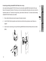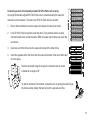
1
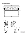
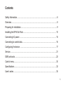
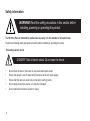
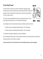
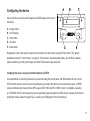
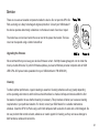
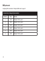
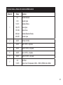
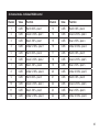
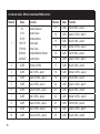
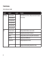
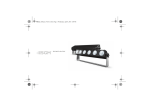
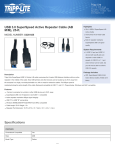
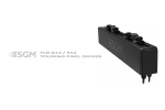
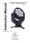
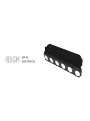
SP∙6
SIX PACK
SP-6 Six Pack dimensions
All dimensions in mm.
Drawing not to scale.
2
SP-6 SIX PACK
USER MANUAL REV. 1
© 2012 SGMTM. Information subject to change without notice. SGM and all affiliated companies disclaim liability for any injury, damage, direct or indirect loss, consequential or
economic loss or any other loss occasioned by the use of, inability to use or reliance on
the information contained in this manual. The SGM logo, the SGM name and all other
trademarks in this document pertaining to services or products by SGM or its affiliates and
subsidiaries are trademarks owned or licensed by SGM or its affiliates or subsidiaries.
English edition
3
4
Contents
Safety information.................................................................................................... 6
Overview.................................................................................................................. 8
Preparing for installation........................................................................................... 9
Installing the SP-6 Six Pack................................................................................... 10
Connecting AC power............................................................................................. 15
Connecting to control data..................................................................................... 16
Configuring the device ........................................................................................... 17
Service................................................................................................................... 21
DMX protocols........................................................................................................ 22
Control menu.......................................................................................................... 30
Specifications......................................................................................................... 32
User’s notes........................................................................................................... 35
5
Safety information
WARNING! Read the safety precautions in this section before
installing, powering or operating this product.
The SP-6 Six Pack is intended for professional use only. It is not suitable for household use.
Review the following safety precautions carefully before installing or operating the device.
Preventing electric shock
DANGER! Risk of electric shock. Do not open the device.
•
•
•
•
•
6
Do not open the device; there are no user-serviceable parts inside.
Ensure that power is cut off when wiring the device to the AC mains supply.
Ensure that the device is electrically connected to earth (ground).
Do not apply power if the device is in any way damaged.
Do not submerse the fixture in water or liquid.
WARNING! Take measures to prevent burns and fire.
•
•
•
•
•
•
Install in a location that prevents accidental contact with the device.
Install only in a well-ventilated space.
Install at least 0.3 m (12 in.) away from objects to be illuminated.
Do not paint, cover, or modify the device, and do not filter or mask the light.
Keep all flammable materials well away from the device.
Allow the device to cool for 15 minutes after operation, before touching it.
WARNING! Take measures to prevent personal injury.
•
•
•
•
Do not look directly at the light source from close range.
Take precautions to prevent injury due to falls when working at height.
Ensure that the device is always securely fastened with suitable hardware.
For elevated installations, secure the fixture with a suitable safety cable, and always comply with relevant load
dimensioning and safety standards and requirements.
7
Overview
The SP-6 Six Pack is a pixel array based on the popular blinder—but the traditional halogen lamps have been replaced
with RGBA LEDs. The fixture incorporates six powerful 35 W colour mixable LEDs, with individual DMX control over
each pixel, enabling a creative lighting designer to paint light canvasses, display animated text or programmed patterns.
The SP-6 Six Pack can even emulate the decay effect of halogen lamps (tungsten response emulation). As the fixture
is rectangular, groups of up to eight fixtures can be flown in vertical or horizontal arrays, which in turn can be linked
together into larger matrixes. The fixture offers built-in dimming, RGBA color mixing, color temperature correction, daisychainable power and DMX sockets, configuration via RFID, and a lamp life expectancy of 50,000 hours.
A
Tilt locks
B
DMX in
C
Fuse holder
D
Power in
E
Safety cable eyelet
F
OLED display and control panel
G
Bracket/stand
H
RFID interface
I
DMX out cable
J
Gortex membrane
K
Power out cable
8
Preparing for installation
Unpack the device and inspect it to ensure that it has not been damaged in transport.
The SP-6 Six Pack is supplied with a stand bracket and two snap-lock brackets.
The fixture is not designed for permanent outdoor installation, but it does have an ingress protection (IP) rating of 65.
This means that it is protected from:
•
•
Dust, to the degree that there is no ingress of dust.
Lower pressure jets of water from any direction.
When selecting a location for the device, ensure that it:
•
•
Is situated away from public thoroughfares and protected from contact with people.
Has adequate ventilation.
9
Installing the SP-6 Six Pack
WARNING! If the device has been operating, always allow it cool for 15 minutes
The SP-6 Six Pack may be installed in any orientation. The angle of the fixture can be
adjusted using the tilt locks at either end of the fixture.
The fixture is supplied with a bracket that can be bolted to a surface using M12 hardware, or
used to fly a single fixture at elevation using clamps or similar. The bracket is not designed to
support the weight of more than one fixture.
WARNING! Always secure an elevated SP-6 Six Pack with a safety cable as backup
When flying the fixture at elevation, always fasten a safety cable between the load-bearing support structure and the
attachment point on the device. The safety cable must be able to bear at least 10 times the weight of the device (see
“Specifications” on page 32).
10
Mounting fixtures in an array
WARNING! Do not connect more than eight SP-6 Six Packs together in a single array
The fixture is supplied with brackets that can be used to connect up to eight SP-6 Six Pack
fixtures to each other in a vertical or horizontal array, or both.
To mount the brackets:
1.
Unscrew the tilt locks on each side of the fixture and detach the stand.
2.
Remove the two Torx 25 screws that hold the safety cable eyelet in place and
remove the eyelet.
3.
Attach the snap lock brackets as shown, so that the male and female parts are
placed at opposite ends.
1
2
The device at the top of an array must always be flown using an SGM top bracket or
suitable mounting hardware attached to the eye bolts at each end of the device. Top
brackets for horizontal or vertical arrays can be purchased from your SGM dealer.
Always ensure that each device in an array has a safety cable connecting it to the load
bearing structure, and not simply to another fixture in the array.
3
11
Connecting vertically-oriented SP-6 Six Packs into an array
Up to eight vertically-aligned SP-6 Six Packs can be connected using M8x50 bolts inserted in the eye
holes on the snap-lock brackets. If the array is to be curved along the vertical plane, then only one bolt is
required at each end. To achieve a flat, rigid array, insert bolts in both holes. To connect one horizontally
oriented SP-6 Six Pack device to another:
1.
Ensure that both devices have the snap-lock brackets mounted.
2.
Lift a SP-6 Six Pack into position under the other so that the bolt eye holes on each fixture are
aligned.
3.
Insert one (for curved array) or two (for flat array) M8x50 bolts into the bolt holes and secure them
tightly.
12
Connecting a stack of horizontally-oriented SP-6 Six Packs into an array
Up to eight horizontally-aligned SP-6 Six Packs can be connected using the snap-lock
connectors on the brackets. To connect one SP-6 Six Pack device to another:
1.
Ensure that both devices have the snap-lock brackets mounted at each end.
2.
Lift a SP-6 Six Pack into position under the other. Every alternate device must be
mounted upside down so that the built-in DMX and power patch cables can reach the
next device.
3.
Insert one end of the fixture into the snap-lock bracket of the other fixture.
4.
Insert the opposite end of the fixture into the snap-lock bracket of the other fixture and
click into place.
Devices connected using the snap-lock connectors can be curved
outwards at an angle of 29°.
To detach one fixture from another, release the lock by pulling the small ring at
the female socket, detach that end and pull the opposite end free.
13
Connecting arrays together into a larger matrix
Any single fixture may not be loaded with the weight of more than seven other fixtures in an array. Arrays can be
connected to other arrays, but each array must have its own secure correction to a load bearing structure, and not have
its weight supported by another array. Connections between one array and another are for the prupose of controlling
pitch (angle) or to obtain rigidity. To connect any two:
•
•
Vertical-stack-arrays (see “Connecting vertically-oriented SP-6 Six Packs into an array” on page 12) along the:
•
Horizontal plane, side-by-side, use the snap-lock connectors on the end brackets.
•
Vertical plane, one above or below the other, use M8x50 bolts in the bolt holes in the brackets at the ends
of each fixture. Use two bolts between each fixture to achieve a rigid flat structure, or a single bolt between
each fixture to adjust the pitch angle.
Horizontal-stack-arrays (see “Connecting a stack of horizontally-oriented SP-6 Six Packs into an array” on page
13) along the:
•
Horizontal plane, side-by-side, use M8x50 bolts in the bolt holes in the brackets at the ends of each fixture.
Use two bolts between each fixture to achieve a rigid flat structure, or a single bolt between each fixture to
adjust the pitch angle.
•
Vertical plane, one above or below the other, use the snap-lock connectors on the brackets.
These connection methods must only be used to control the pitch (angle) along the horizontal axis, not as a form for
load bearing.
14
Connecting AC power
The SP-6 Six Pack can operate on any 100–240 V, 50/60 Hz AC mains power supply.
Connect the device to power using a cable with a Neutrik powerCON TRUE1 connector (not
supplied). The device can feed power to another device in a daisy chain using the built-in
0.5 m (20 in.) power-out cable.
The device must be grounded/earthed and be able to be isolated from AC power. The AC
power supply must incorporate a fuse or circuit breaker for fault protection.
Due to the high level of in-rush current when the devices are started, ensure that no more than:
•
4 Six-Pack devices are connected through the same type C, 10 A circuit breaker.
•
9 Six-Pack devices are connected through the same type C, 16 A circuit breaker.
For assistance with alternative configurations, contact your SGM agent.
After connecting the Six Pack to power, run the automated on-board test to ensure that the device and each LED are
functioning correctly. See “Control menu” on page 30.
Do not open the fixture or connect the device to an electrical dimmer system, as this can damage it.
15
Connecting to control data
The device complies with the Digital MultipleX (DMX) communications protocol. It is controlled using a DMX control
device and must be connected to the data link using a DMX cable with a 5-pin DMX connector.
Connect the DMX in socket and out socket to the DMX data link. The device can feed control signals to another device
in a daisy chain using the built-in 0.5 m (20 in.) DMX-out cable.
Use only IP-rated XLR connectors when using the fixture outdoors.
Terminate the last device in the data link by connecting a 5-pin XLR DMX terminator to its DMX-out socket. A terminator
can be purchased from your cable or lighting supplier, or made by soldering a 120-ohm resistor between pins 2 and 3
in a 5-pin XLR DMX connector.
Pin
16
Signal
1
Signal common
2
Data -
3
Data +
4
Not used
5
Not used
Configuring the device
Set up the fixture using the control panel and OLED display at the rear of
the fixture:
A - Escape button
B - OLED display
C - Enter button
D - Up button
E - Down button
Navigate the menus and options using the arrow buttons and select items using the Enter button. The options
available are listed in “Control menu” on page 30. If the device is mounted upside down, you can flip the display
(and the buttons) by holding the Escape and Enter button down at the same time.
Configurig the device using an Android telephone via RFID
As an alternative to connecting the device to power and using the control panel, the DMX address of one or more
SP-6 Six Pack devices can be read and set wirelessly, even when the fixture is not connected to power, via RFID,
using an Android smart phone that has NFC support (ISO 15693 and ISO 18000-3 mode 1 compatible, operating
on 13.56 MHz ±7k Hz carrier frequency) and an application (app) developed by SGM (close to release at the time of
writing this manual. Search Google Play, or contact your SGM agent for more information).
17
About DMX
The SP-6 Six Pack is controlled using signals sent by a DMX controller on a number of channels (6, 7, 18, 24, 28
or 48 depending on the DMX mode that has been set). The first channel used to receive data from a DMX control
device is known as the DMX address. Each SP-6 Six Pack must have a DMX address set. For example, if a SP-6
Six Pack has a DMX address of 10 and it is in 7-channel DMX mode, then it uses channels 10, 11, 12, 13, 14, 15
and 16. The following fixture in the DMX chain could then be set to a DMX address of 17. If two or more DMX
devices of the same type have the same DMX address, then they will mimic each other’s behavior. Incorrect settings
will result in unpredictable responses to the lighting controller.
Setting the DMX address
After powering the SP-6 Six Pack on, the display shows the currently selected DMX address and other information.
A - Operational mode
B - DMX address
C - Data indicator
D - Data protocol
To change the address setting, press the up arrow to increase the address,
or the down arrow to decrease the setting. When the desired address
is displayed, press Enter to save the setting. For your convenience, the
suggested DMX address of the next fixture is displayed to the right. Note that
channel spacing is determined by the DMX mode.
18
A
B
C D
6CH RGB
8
・DMX
SET DMX ADR
10
NEXT FIX
13
See the “DMX protocols” on page 22 for specific DMX control values, and “Connecting to control data” on page
16 for DMX connection requirements.
Setting the DMX mode
Using the control panel, specify the DMX mode that provides the device controls that you require:
DMX mode
Function
6
Halogen dimmer emulation.
7
Effects and collective control of pixels as a group.
18
Individual control of RGB mix for individual pixels with automated amber mixing.
24
Individual control of RGBA mix for individual pixels.
28
Effects and individual control of RGBA mix for individual pixels.
48
Fine and coarse control of RGBA mix for individual pixels.
Setting the dimming curve
The diming curve is the degree of fineness in control available at low light levels. There are two dimming curve
options available on the SP-6 Six Pack, linear or gamma corrected. Linear control provides uniform adjustment
throughout the control action, whereas gamma corrected dimming provides finer control at low light levels, where
the eye is more sensitive to change. By default, the SP-6 Six Pack uses gamma corrected dimming. For uniform
response, set all devices to the same dimming curve. To set the desired dimming curve, use the control panel to
access the Settings menu, and choose the required dimmer curve setting.
19
Temperature dimming mode options
As the device warms up, the color of the light changes slightly. By default, the device will dim the colors
according to the temperature of the device, to keep the color output constant. This can be disabled by selectig
the ‘Max Power’ option available under the Temperature Dim Mode from the Settings menu (see “Control menu”
on page 30).
Flipping the OLED display
If the device is installed hanging from a truss or structure, it may be upside down, in which case it might be a
good idea to flip the screen so that it is easy to read. Press the enter and escape buttons at the same time to flip
the display.
Setting the OLED display screen saver
By default the OLED display turns off after a short period when the control panel is not in use, but it can be
set so that it dims. Pressing any key will always turns on the display or restore it to normal brightness. To set
the OLED screen saver mode, use the control panel to access the Settings menu, and choose one of the two
display saver modes.
Two-way DMX communication
The RDM address used for two way DMX communication can be seen using the control menus (See “Control
menu” on page 30.)
20
Service
There are no user-serviceable components inside the device. Do not open the SP-6 Six
Pack, as doing so is likely to damage its ingress protection. Consult your SGM dealer if
the device operates abnormally, is defective or otherwise in need of service or repair.
The mains fuse can be found under the cover next to the power inlet socket. The fuse
cover can be opened using a slotted screwdriver.
Upgrading the firmware
We recommend that you to keep your device’s firmware current. Visit http://www.sgmsupport.com to obtain the
most up-to-date firmware. To perform firmware updates, you need a Windows personal computer and an SGM
USB 5-Pin-XLR upload cable (available from your SGM distributor: P/N 40500201).
Cleaning
To obtain optimal performance, regular cleaning is essential. Cleaning schedules will vary greatly depending
on the operating environment, and the fixture should therefore be checked at frequent intervals within the first
few weeks of operation to see whether cleaning is necessary. This procedure will allow you to assess cleaning
requirements in your particular situation. If in doubt, consult your SGM dealer for a suitable maintenance
schedule. Clean the SP-6 Six Pack using a soft cloth dampened with a solution of water and a mild detergent. Do
not use products that contain solvents, abrasives or caustic agents for cleaning, as they can cause damage to
both hardware, cables and connectors.
21
DMX protocols
Configuring DMX is described in “Setting the DMX mode” on page 19.
6 channel mode - Halogen dimmer emulation
22
Channel
Value
Function
1
0-255
“Halogen” 0-100% - pixel 1
2
0-255
“Halogen” 0-100% - pixel 2
3
0-255
“Halogen” 0-100% - pixel 3
4
0-255
“Halogen” 0-100% - pixel 4
5
0-255
“Halogen” 0-100% - pixel 5
6
0-255
“Halogen” 0-100% - pixel 6
7 channel mode - effects with collective RGBA control
Channel
Value
1
0-7
8-15
16-151
152-175
176-199
200-244
245-255
Function
Shutter Blackout
Shutter Open
Variable Strobe
Pulse Open
Pulse Close
2
0-255
Dimmer 0-100%
3
0-255
Red 0-100% - all pixels
4
0-255
Green 0-100% - all pixels
5
0-255
Blue 0-100% - all pixels
6
0-255
Amber 0-100% - all pixels
7
0-9
10-255
No Effect
Amber Color Temperature 3200 k - 6500 k (RGBA Set to MAX)
Variable Random Strobe
Shutter Open
23
18 channel mode - Individual RGB control with automated amber
Channel
Value
Function
1
0-255
Red 0-100% - pixel 1
2
0-255
3
0-255
4
24
Channel
Value
Function
10
0-255
Red 0-100% - pixel 4
Green 0-100% - pixel 1
11
0-255
Green 0-100% - pixel 4
Blue 0-100% - pixel 1
12
0-255
Blue 0-100% - pixel 4
0-255
Red 0-100% - pixel 2
13
0-255
Red 0-100% - pixel 5
5
0-255
Green 0-100% - pixel 2
14
0-255
Green 0-100% - pixel 5
6
0-255
Blue 0-100% - pixel 2
15
0-255
Blue 0-100% - pixel 5
7
0-255
Red 0-100% - pixel 3
16
0-255
Red 0-100% - pixel 6
8
0-255
Green 0-100% - pixel 3
17
0-255
Green 0-100% - pixel 6
9
0-255
Blue 0-100% - pixel 3
18
0-255
Blue 0-100% - pixel 6
24 channel mode - Individual RGBA control
Channel
Value
Function
Channel
Value
Function
1
0-255
2
0-255
Red 0-100% - pixel 1
13
0-255
Red 0-100% - pixel 4
Green 0-100% - pixel 1
14
0-255
Green 0-100% - pixel 4
3
0-255
Blue 0-100% - pixel 1
15
0-255
Blue 0-100% - pixel 4
4
0-255
Amber 0-100% - pixel 1
16
0-255
Amber 0-100% - pixel 4
5
0-255
Red 0-100% - pixel 2
17
0-255
Red 0-100% - pixel 5
6
0-255
Green 0-100% - pixel 2
18
0-255
Green 0-100% - pixel 5
7
0-255
Blue 0-100% - pixel 2
19
0-255
Blue 0-100% - pixel 5
8
0-255
Amber 0-100% - pixel 2
20
0-255
Amber 0-100% - pixel 5
9
0-255
Red 0-100% - pixel 3
21
0-255
Red 0-100% - pixel 6
10
0-255
Green 0-100% - pixel 3
22
0-255
Green 0-100% - pixel 6
11
0-255
Blue 0-100% - pixel 3
23
0-255
Blue 0-100% - pixel 6
12
0-255
Amber 0-100% - pixel 3
24
0-255
Amber 0-100% - pixel 6
25
28 channel mode - Effects & individual RGBA control
Channel
1
26
Value
0-7
8-15
16-151
152-175
176-199
200-244
245-255
Function
Shutter Blackout
Shutter Open
Variable Strobe
Pulse Open
Pulse Close
Variable Random Strobe
Shutter Open
Channel
Value
Function
11
0-255
Red 0-100% - pixel 3
12
0-255
Green 0-100% - pixel 3
13
0-255
Blue 0-100% - pixel 3
14
0-255
Amber 0-100% - pixel 3
15
0-255
Red 0-100% - pixel 4
16
0-255
Green 0-100% - pixel 4
2
0-255
Dimmer 0-100%
17
0-255
Blue 0-100% - pixel 4
3
0-255
Red 0-100% - pixel 1
18
0-255
Amber 0-100% - pixel 4
4
0-255
Green 0-100% - pixel 1
19
0-255
Red 0-100% - pixel 5
5
0-255
Blue 0-100% - pixel 1
20
0-255
Green 0-100% - pixel 5
6
0-255
Amber 0-100% - pixel 1
21
0-255
Blue 0-100% - pixel 5
7
0-255
Red 0-100% - pixel 2
22
0-255
Amber 0-100% - pixel 5
8
0-255
Green 0-100% - pixel 2
23
0-255
Red 0-100% - pixel 6
9
0-255
Blue 0-100% - pixel 2
24
0-255
Green 0-100% - pixel 6
10
0-255
Amber 0-100% - pixel 2
25
0-255
Blue 0-100% - pixel 6
28 channel mode - Effects & individual RGBA control
26
27
0-255
Amber 0-100% - pixel 6
0-7
Disable halogen-style
dimming
Emulate halogen-style
dimming
Not used
8-15
16-255
28
10-255
Amber Color Temperature 3200k
- 6500k (RGBA Set to MAX)
27
48 channel mode - Coarse & fine individual RGBA control (16-bit)
28
Channel
Value
Function
Channel
Value
Function
1
0-255
Red 0-100% - pixel 1
2
0-255
Red fine - pixel 1
3
0-255
Green 0-100% - pixel 1
4
0-255
Green fine - pixel 1
5
0-255
Blue 0-100% - pixel 1
6
0-255
Blue fine - pixel 1
7
0-255
Amber 0-100% - pixel 1
8
0-255
Amber fine - pixel 1
9
0-255
Red 0-100% - pixel 2
10
0-255
Red fine - pixel 2
11
0-255
Green 0-100% - pixel 2
12
0-255
Green fine - pixel 2
13
0-255
Blue 0-100% - pixel 2
14
0-255
Blue fine - pixel 2
15
0-255
Amber 0-100% - pixel 2
16
0-255
Amber fine - pixel 2
17
0-255
Red 0-100% - pixel 3
18
0-255
Red fine - pixel 3
19
0-255
Green 0-100% - pixel 3
20
0-255
Green fine - pixel 3
21
0-255
Blue 0-100% - pixel 3
22
0-255
Blue fine - pixel 3
23
0-255
Amber 0-100% - pixel 3
24
0-255
Amber fine - pixel 3
25
0-255
Red 0-100% - pixel 4
26
0-255
Red fine - pixel 4
27
0-255
Green 0-100% - pixel 4
28
0-255
Green fine - pixel 4
48 channel mode - Coarse & fine individual RGBA control (16-bit)
29
0-255
Blue 0-100% - pixel 4
30
0-255
Blue fine - pixel 4
31
0-255
Amber 0-100% - pixel 4
32
0-255
Amber fine - pixel 4
33
0-255
Red 0-100% - pixel 5
34
0-255
Red fine - pixel 5
35
0-255
Green 0-100% - pixel 5
36
0-255
Green fine - pixel 5
37
0-255
Blue 0-100% - pixel 5
38
0-255
Bluefine - pixel 5
39
0-255
Amber 0-100% - pixel 5
40
0-255
Amber fine - pixel 5
41
0-255
Red 0-100% - pixel 6
42
0-255
Red fine - pixel 6
43
0-255
Green 0-100% - pixel 6
44
0-255
Green fine - pixel 6
45
0-255
Blue 0-100% - pixel 6
46
0-255
Blue fine - pixel 6
47
0-255
Amber 0-100% - pixel 6
48
0-255
Amber fine - pixel 6
29
Control menu
Default settings are in bold.
Level 1
Level 2
Level 3
Function
DMX Mode
6 Channel Mode
-
Selects DMX mode. Refer to DMX protocol table for features
of each mode.
Firmware Version
-
Displays installed software version number.
Serial Number
-
Displays the serial number of the device.
RDM ID
-
Displays address used for two-way DMX communication.
DMX View
-
Displays received DMX levels.
Temperatures
-
Displays temperatures in fixture.
Log
-
Displays recorded operating data and error codes.
7 Channel Mode
18 Channel Mode
24 Channel Mode
28 Channel Mode
48 Channel Mode
Info
30
Level 1
Level 2
Level 3
Function
Settings
Dimming Curve
Linear
Provides equal resolution dimming from 0 to 100%.
Gamma
Corrected
Provides high resolution dimming at low levels.
Disable
Selects normal control panel display.
Enable
Flips control panel display and buttons. Used when the fixture
is upside down
Screen Dim
Dims the OLED display, when the control panel is not in use
Screen Off
Turns off OLED display, when the control panel is not in use.
Standard
The colors dim in relation to the temperature of the device, to
keep the color output constant.
Max Power
The output is not adjusted in relation to the temperature of the
Flip Screen
Display Saver
Temperature Dim
Mode
fixture.
Test
Off
-
Stops test sequence execution.
Automated Test
-
Initiates a self-test sequence.
Burn In Test 30
min.
Display Test
A test that runs for 30 minutes and powers down the fixture.
-
All pixels in the OLED display are turned on.
31
Specifications
PHYSICAL
Length x width x height ................................................................................ 739 x 175 x 107 mm (29.9 x 6.9 x 4.2 in.)
Weight .................................................................................................................................................... 8 kg (17.6 lbs)
LIGHT SOURCE AND OPTICS
6 x RGBA power LEDs................................................................................................................................. 35 W each
LEDs lifetime............................................................................................................................................. 50,000 hours
Luminous flux........................................................................................................................................... 7,700 lumens
Spread angle............................................................................................................................................................ 14°
CONSTRUCTION
Housing ........................................................................................................................................................ Aluminium
Finish .................................................................................................................................Electrostatic powder coating
INSTALLATION
Orientation................................................................................................................................................................ Any
Minimum distance between units .............................................................. Horizontal: 0 mm, Vertical: 13 mm (1/2 in.)
32
AMBIENT OPPERATING CONDITIONS
Maximum ambient temperature (Ta)....................................................................................................... 40° C (104° F)
Minimum ambient temperature (Ta)......................................................................................................... -10° C (14° F)
Operating humidity ............................................................................................................................................... 100%
IP rating ................................................................................................................................................................. IP 65
PROGRAMMING AND CONTROL
DMX control .................................................................................................................. 6, 7, 18, 24, 28 or 48 channels
Local control ................................................................................. OLED graphical display / 4 buttons menu structure
Software upgrade ............................................................................................................................................ via DMX
Contactless interface...................... via RFID using an Android telephone that has NFC support and SGM application
CONNECTIONS
AC power input......................................................................................................... Neutrik powerCON TRUE1 socket
AC power output....................................................................0.5 m (20 in.) Neutrik powerCON TRUE1 cable with plug
DMX data input ...................................................................... Water resistant Neutrik Locking 5-pin XLR male socket
Driver data output ............................. 0.5 m (20 in.) water resistant Neutrik Locking 5-pin XLR female cable with plug
33
ELECTRICAL
AC power ..................................................................................................................................... 100–240 V, 50/60 Hz
Maximum total power consumption (all LED pixels on)....................................................................................... 250 W
Power consumption (all LED pixels off) .................................................................................................................. 7 W
TYPICAL POWER AND CURRENT
100 V, 60 Hz ..............................................................................................................................225 W, 2.28 A, 0.99 PF
120 V, 60 Hz ..............................................................................................................................225 W, 1.89 A, 0.99 PF
208 V, 60 Hz ................................................................................................................................225 W, 1.1 A, 0.99 PF
230 V, 50 Hz ................................................................................................................................225 W, 1.0 A, 0.97 PF
240 V, 50 Hz ..............................................................................................................................225 W, 0.98 A, 0.95 PF
PF power factor is measured at full load with all LEDs 100% driven.
FUSES
Main fuse (located at the Mains inlet socket).......................................................................................................... T5A
2 x power supply fuses (not user-replaceable)................................................................................................... T3,15A
Specifications subject to change without notice
34
User’s notes
35
36