1
M P C 5 5 5 3 D E M O
0 9 / 0 6 / 0 5
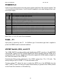
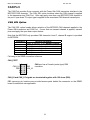
USER LED
User LED header provides access to the user LED 1 to 8. Connector pin 1 to 8 organization is
provided in a one to one method to the individual indicators LED 1 to 8. The LED indicators
are buffered for minimal drive current requirement (~300ua). Indicators will turn on with a logic
high or 2.5 to 5V input at the respective connector pin.
USER Switch
User Switch provides access to the user 8 position DIP Switch. Connector pin 1 to 8
organization is provided in a one to one organization to the individual DIP switch positions 1 to
8. The switch connections are pulled low with 10K ohm resistors when the switch position in
the off position. Switch positions placed in the ON position will provide a 3.3V output to the
connector.
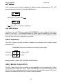
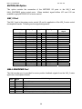
USER_DEV
User DEV provides access to the 4 push switches (SW1 – SW4), speaker, and 2 user
potentiometers (RV1 and RV2).
PIN #
1
2
3
4
5
6
7
8
USER COMPONENT CONNECTION
SW1 out, de-bounced CMOS drive 0 or 3.3V, active low.
SW1 out, de-bounced Open Drain output, active low, 10K ohm pull-up
to 3.3V. Suitable for IRQ input signal drive.
SW2 out, active low, 10K ohm pull-up to 3.3V.
SW3 out, active low, 10K ohm pull-up to 3.3V.
SW4 out, active low, 10K ohm pull-up to 3.3V.
SPEAKER amp input. 0 to 5Vpp, volume adjust with SPKR_VOL.
RV1 center tap, 0 – 5V adjustment
RV2 center tap, 0 – 5V adjustment
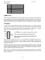
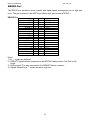
SW1 – SW4 Push Switches
The push switches provide momentary active low input for user applications. SW1 has
additional features of being de-bounced for no glitch operation and push-pull output on pin 1 or
open drain output on pin 2. Typical user application would be to provide program control or
menu selection input.
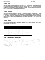
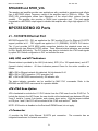
SW3_UP and SW4_Down are also provided for the UNI_3 Port motor control operation when
the MOTOR_EN option is installed.
8