1
UNIVERSITI TEKNOLOGI MALAYSIA
DECLARATION OF THESIS / UNDERGRADUATE PROJECT PAPER AND COPYRIGHT
Author’s full name :
HASRIL IZHAM B ISMAIL @ ABU HASSAN
Date of birth
:
21ST APRIL 1988
Title
: OMNI DIRECTIONAL LINE FOLLOWING MOBILE ROBOT
Academic Session: 2010/2011
I declare that this thesis is classified as :
CONFIDENTIAL
(Contains confidential information under the Official Secret
Act 1972)*
RESTRICTED
(Contains restricted information as specified by the
organisation where research was done)*
OPEN ACCESS
I agree that my thesis to be published as online open access
I acknowledged that Universiti Teknologi
(full text)Malaysia reserves the right as follows :
1. The thesis is the property of Universiti Teknologi Malaysia.
2. The Library of Universiti Teknologi Malaysia has the right to make copies for the purpose
of research only.
3. The Library has the right to make copies of the thesis for academic exchange.
Certified by :
SIGNATURE
SIGNATURE OF SUPERVISOR
880421-26-5559
DR YEONG CHE FAI
(NEW IC NO. /PASSPORT NO.)
Date: 15 May 2011
NOTES :
*
NAME OF SUPERVISOR
Date: 15 May 2011
If the thesis is CONFIDENTIAL or RESTRICTED, please attach with the letter from
the organisation with period and reasons for confidentiality or restriction.
.
“I hereby declare that I have read this thesis and in my opinion this thesis is
sufficient in terms of scope and quality for the award of the degree of
Bachelor of Engineering (Electrical – Mechatronics)”
Signature
: ..……………………….
Name of Supervisor : DR YEONG CHE FAI
Date
: 15 MAY 2011
OMNI DIRECTIONAL LINE FOLLOWING MOBILE ROBOT
HASRIL IZHAM B ISMAIL @ ABU HASSAN
A thesis submitted in partial fulfillment of the requirements for the award of the degree
of Bachelor of Engineering (Electrical - Mechatronics)
Faculty of Electrical Engineering,
Universiti Teknologi Malaysia
MAY 2011
ii
DECLARATION
“I hereby declare that this thesis entitled “Omni Directional Line Following Mobile
Robot” is the result of my own research except as cited in the references. The thesis has
not been accepted for any degree and is not concurrently submitted in candidature of any
other degree.
Signature
: …………………….
Name of Candidate
: Hasril Izham B Ismail @ Abu Hassan
Date
: 10 May 2011
iii
DEDICATION
To my beloved friends and family members for their warmest support
iv
ACKNOWLEDGEMENT
I would like to take this opportunity to express my sincere appreciation to my
Final Year Project (FYP1) supervisor, En Mohamad Amir bin Shamsudin and (FYP2)
supervisor, Dr Yeong Che Fai. I would like to thank them for their supervision, guidance
and support throughout this project. Their ideas and suggestions were invaluable assets
to me whenever problems arose in the project.
Besides, I would also like to thank my family for giving me financial and mental
support. They also provide me the tools that I need to complete my project. Without
their support, I would have difficulties during completing this project.
Furthermore, I would like to thank my friends especially for my course mate for
providing some tools and facilities I need for this project. Also to the technicians of the
laboratory that helps me to build my robot base. Their support helps to complete my
project smoothly.
Last but not least, I would like to express my appreciation to anybody who
directly or indirectly has contributed to the success of this project.
v
ABSTRACT
A variety of designs of mobile robot have been developed in recent years in
order to improve their omni directional mobility and practical applications. Omni
directional mobile robot has vast advantages over conventional design likes differential
drive in term of mobility in congested environments. The main purpose of this research
is to design, develop and implement an Omni Directional Line Following Mobile Robot
with transwheels for autonomous navigation. Using these transwheels, the mobile robot
is provided with three degree of freedom (DOF) mobility. In this project,
microcontroller PIC16F777 is used as the brain of the robot to control the robot’s
movements where all data is processed. To move in omni directional, 3 transwheels are
used. The three transwheels are driven by three DC Geared motor independently. IR
sensors are used to detect the line. MPLAB IDE is used to write the source code and
then generate the HEX file. The HEX file is then flashed into the PIC using the USB
Programmer. Experiments were performed to analyze the motion characteristic of the
mobile robot motions. As the result, the Omni Directional Line Following Mobile Robot
able to move in omni directional and follow the line in particular direction that has been
assign.
vi
ABSTRAK
Kepelbagaian rekabentuk robot bergerak telah dibangunkan kebelakangan ini
dalam usaha memperbaiki keupayan pergerakannya dan aplikasi praktikal. Robot
berarah omni mempunyai kelebihan berbanding robot lain yang terbatas kerana
keupayaannya bergerak dalam persekitaran yang sesak. Objektif utama penyelidikan ini
adalah merekabentuk, membangun dan mengimplimentasikan robot berarah omni
mengikut jalan yang dilengkapi roda transwheels untuk bergerak secara berpanduan.
Dengan menggunakan tayar transwheels, robot bergerak memberikan tiga darjah
kebebasan dalam pergerakan. Dalam projek ini, cip PIC16F777 digunakan sebagai pusat
kawalan utama robot untuk mengawal pergerakan robot di mana semua data diproses.
Untuk bergerak secara omni, tiga tayar transwheels digunakan. Ketiga-tiga tayar
transwheels ini dipandu oleh tiga motor arus terus secara berasingan.IR sensor
digunakan untuk mengesan jalan. MPLAB IDE digunakan untuk menulis kod program
dan kemudian menghasilkan fail HEX. File HEX ini kemudian akan dimasukkan ke cip
menggunakan alat program USB. Ujikaji telah dijalankan untuk menganalisa ciri-ciri
pergerakan robot bergerak. Hasilnya, robot berarah omni mengikut jalan berupaya
bergerak secara omni dan mengikut jalan dalam arah yang ditetapkan.
vii
TABLE OF CONTENTS
CHAPTER
1
TITLE
PAGE
DECLARATION
ii
DEDICATION
iii
ACKNOWLEDGEMENTS
iv
ABSTRACT
v
ABSTRAK
vi
TABLE OF CONTENTS
vii
LIST OF TABLES
x
LIST OF FIGURES
xi
LIST OF ABBREVIATIONS
xiii
LIST OF APPENDIXES
xiv
INTRODUCTION
1
1.1 Project Background
1
1.2 Problem Statements
2
1.3 Objectives of Projects
3
1.4 Scopes of Projects
3
1.5 Thesis Layout
4
1.6 Planning
4
viii
2
LITERATURE REVIEW
6
2.1 Introduction
6
2.2 Omni Directional Wheel Design
7
2.2.1 A Design of Omni Directional Mobile Robot
7
2.2.2 Design of an omni directional robot for FIRA
9
ROBOSOT.
2.3 Omni Directional Vehicles
2.3.1 The Omni Directional Writobot by Muhamad Nabil
10
10
bin Mansor (2007/2008)
2.3.2 Omni Directional Mobile Home Care Robot
12
2.3.3 Moving Target Tracking of Omni Directional
13
Robot with Stereo Cameras
2.3.4 Omni Directional Mobile Robot using Mecanum
14
Wheel
3
2.4 Summary of Chapter 2
16
METHODOLOGY
17
3.1 Hardware and Mechanical Design
20
3.1.1 Transwheels
22
3.1.2 DC Geared Motor (MO-SPG-30-20K)
23
3.2 Electronic and Circuit Design
24
3.2.1 PIC Start Up Kit (SK40C)
25
3.2.2 LiPo Battery
26
3.2.3 I/O Pin Assignation for PIC16F777
27
3.2.4 Circuit Connection for DC Geared Motor’s Motor
30
Driver L298N
3.2.5 Circuit Connection of IR Sensors
32
3.2.6 Combine All Circuit
33
ix
4
3.3 Programming Design
35
3.4 Summary of Chapter 3
40
RESULT AND DISCUSSION
41
4.1 Final Hardware Design
41
4.2 Line Following Feature
43
4.2.1 Omni Line Following
43
4.2.2 Normal Line Following
45
4.2.3 Comparison between Omni Directional and Normal
46
Movement
5
4.3 Summary of Chapter 4
48
CONCLUSION AND RECOMMENDATION
49
5.1 Conclusion
49
5.2 Problem
50
5.3 Limitation
51
5.4 Recommendation
51
REFERENCES
52
APPENDIXES
53-72
x
LIST OF TABLES
TABLE
TITLE
PAGE
1.6
Gantt chart Of the Project Schedule for FYP
5
3.1
PIC16F777 device Features
28
4.1
Hardware Specification
42
4.2
Time Taken to Reach the Destination
47
xi
LIST OF FIGURES
FIGURE
TITLE
PAGE
2.1
The Mecanum wheel
8
2.2
Design of mobile robot using the mecanum wheel
8
2.3
3 transwheels
9
2.4
4 transwheels
10
2.5
Omni directional Writobot
11
2.6
Omni directional mobile home care robot
12
2.7
Moving target tracking of omni directional robot with stereo
14
cameras
2.8
Force vector of mecanum wheel
15
2.9
Omni directional mobile robot
15
3.1
Flow chart of methodology
17
3.2
View of mobile base
19
3.3
Different View of Mobile Base
20
3.4
Position of the IR sensor
21
3.5
Transwheels
22
3.6
A MO-SPG-30-20K DC geared motor
23
3.7
Block diagram of the circuit design
24
3.8
SK40C
25
3.9
LiPo Battery
26
3.10
PIC16F777
27
3.11
Pin Diagram of PIC16F777
29
3.12
I/O Assignation for Main Circuit
29
xii
3.13
Pin Diagram and Actual Look of L298N Motor Driver
31
3.14
Circuit Connection of Motor Driver L298N
31
3.15
Circuit Connection of IR Sensors – Part A
32
3.16
Circuit connection of IR Sensors – Part B
33
3.17
Main Circuit
34
3.18
Motor Driver Circuit
34
3.19
All Circuit Mounted on Mobile Base
35
3.20
Flow Chart of Main Program
36
3.21
Flow Chart of Line Following
37
3.22
Sensor Condition to Detect Junction
38
3.23
Path for the Line Following
39
3.24
Sensor for the Line Following
39
4.1
Final Hardware Design
41
4.2
Step on How Mobile Robot Follows Line in Omni Directional
44
Movement
4.3
Step on How Mobile Robot Follows Line in Normal Movement.
45
4.4
Comparison between Omni Directional and Normal Movement
46
xiii
LIST OF ABBREVIATION
A
ADC
-
AUSART
-
C
CD
DC
DOF
FYP
I/O
IR
k
kg
LiPo
mA
mAh
MHz
mm
mNm
MSSP
PIC
PSP
RM
RPM
s
TTL
V
-
Ampere
Analog to Digital Converter
Addressable Universal Synchronous Asynchronous
Receiver Transmitter
Computer
Compact Disc
Direct Current
Degree Of Freedom
Final Year Project
Input/Output
Infra Red
Kilo
Kilogram
Lithium Polimer
mili Ampere
mili Ampere hour
Mega Hertz
Millimeter
miliNewtonmeter
Master Synchronous Serial Port
Peripheral Interface Controller
Parallel Slave Port
Ringgit Malaysia
Revolution Per Minute
second
Transistor-transistor Logic
Voltage
xiv
LIST OF APPENDIXES
APPENDIX
A
TITLE
Source Code for Omni Directional Line Following
Mobile Robot
PAGE
51
1
CHAPTER 1
INTRODUCTION
1.1
Project Background
Omni directional is described as the ability of a system to move
instantaneously in any direction from any configuration. Omni directional mobile
robot has many advantages compared to ordinary mobile robot in term of its
movement. These abilities can overcome the challenges in everyday life. It can move
in any direction without having to turn relative to its base. For example, to move
sideways a differential drive mobile robot can turn 90 degrees, either to left side or
right side. Many design of omni directional have been proposed nowadays because
of its ability to move in special directions.
2
This mobile robot has three degrees of freedom, i.e. two dimensional linear
motions and one dimensional rotational motion. There are three universal wheels
mounted along the edge of the robot chassis 120° apart from each other, and each
wheel has a set of passive rollers aligned with its rim. Because of its special
mechanism, the robot is able to simultaneously rotate and translate.
Omni directional line following mobile robot is a mobile robot that has the
ability to move in omni directional while follow the line assign to it as it path. This
mobile robot consists of 3 transwheels attached to the mobile robot base. It has
sensors to detect the given line, and make it possible to follow the line.
1.2
Problem Statements
Current mobile robot use conventional wheels to move. It has to turn its
mobile robot base to turn either to the left or right. It takes more times and spaces to
move the mobile robot base to the desired place. These problems can be solved by
using an omni directional mobile robot. This mobile robot doesn’t have to turn its
body respective to the direction of the desired place. This kind of movement is more
stable and easier to move without changing the base. This mobile robot operates
autonomously. So it will not require someone to control its movement. Because of its
mobility, it will have many applications either in home, industrial or other area.
3
1.3
Objectives of Project
The main objective of this project is to design and construct a mobile robot
with an ability to move in omni directional. The mobile robot is made by 2mm
thickness aluminium. 3 transwheels are used so that it will move in omni directional.
Each transwheel is driven by a DC geared motor.
Second objective is to enable line following ability of this mobile robot. IR
sensor is used to detect the line. 12 set of IR sensor is used so that it can sense the
line that I have assigned.
1.4
Scopes of Project
The scopes of this project are outlined as following:
1. Design and construct omni directional mobile robot using the transwheels.
2. Moving in fully omni directional way.
3. Omni directional robot able to detect and follow the given line track.
4
1.5
Thesis Layout
This thesis consists of 5 chapters and each chapter is briefly discussed here.
Chapter 1 gives an introduction and overview of this project. The project’s problem
statements, objectives and scopes also included in this chapter. Chapter 2 presents
some of the literature reviews relating to this project. It discussed some
documentation of previous students’ work and others.
Chapter 3 discussed the methodology of the project. Hardware and software
methodology is explained in this chapter. Chapter 4 presents the result of the
developed system and its limitation. Chapter 6 covers the conclusion and the
recommendations for future development.
1.6
Planning
In order to complete this project, proper in planning management will ensure
the task is done based on the schedule. Figure 4.1 below shows the Gantt chart of this
project from semester 1 to semester 2.
5
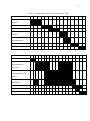
Table 1.1: Gantt chart Of the Project Schedule for FYP
Task / Week
1
2
3
4
5
6
7
8
9
10
11
12
13
14
15
Topic research and
proposal
Literature review
Hardware design
Hardware part's
purchase
Hardware
implementation
FYP1 presentation
Report writing
a) FYP 1
Task / Week
1
2
3
4
5
6
7
8
9
Hardware completion
Software
implementation (
movement )
Software
implementation ( IR
sensor )
Testing and
troubleshoot
Thesis writing
FYP2 presentation
Thesis compilation
b) FYP 2
10 11 12 13 14 15 16 17 18
6
CHAPTER 2
LITERATURE REVIEW
2.1
Introduction
Reviewing similar projects done by other researchers can be a guideline to this
work. The literature review is divided into two parts which are omni directional
wheel design and omni directional vehicle.
7
2.2
Omni Directional Wheel Design
It is important to choose the right omni directional wheel design in order to move
in omni directional. As there are many kinds of omni directional wheels design in the
market, choosing the right type of wheel design based on the requirement and the
usage of the mobile robot is important. There are two types of omni directional wheel
design. They are conventional wheels design and special wheels design. But this
project uses the special wheels design only.
2.2.1
A Design of Omni Directional Mobile Robot
This is a project group by Jefri Efendi Mohd Salih, Mohd Rizon Mohd Juhari,
Sazali Yaacob and Abdul Hamid Adom from Kolej Universiti Kejuruteraan Utara
Malaysia (KUKUM) on 2006.
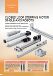
The project uses Mecanum wheels design. Mecanum wheel is based on the
principle of a central wheel with a number of rollers placed at an angle of 45° around
the periphery of the wheel. Depending on each individual and speed wheel direction,
the resulting combination of all these forces produces a total force vector in any
desired direction thus allowing the platform to move freely in direction of resulting
force vector, without changing the direction of the wheel. Using the mecanum wheel,
slipping is a common problem as it has only one roller with a single point of ground
8
contact at any one time. Due to the dynamics of the mecanum wheel, it can create
force vectors in both the x and y-direction while only being driven in the y-direction.
Positioning four mecanum wheels, one at each corner of the mobile base, allows net
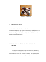
forces to be formed in the x, y and rotational direction. Figure 2.1 shows the
mecanum wheel and Figure 2.2 shows the design of the mobile robot using the
mecanum wheel.
Figure 2.1: The Mecanum wheel
Figure 2.2: Design of mobile robot using the mecanum wheel
9
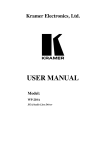
2.2.2
Design of an omni directional robot for FIRA ROBOSOT.
This project constructed by a group of students from Korea Advance Institute
of Science and Technology. They were Naveen Suresh Kuppuswamy, Se-Hyoung
Cho, Daniel Stonier, Sung-Lok Choi and Jong-Hwan Kim.
The transwheel’s unique design contains eight free-turning rollers
perpendicular to the axle arranged around the transwheels periphery. The design
combined with the rotation of the wheel body provides the ability to move in any
direction. It can be used to design either 3 transwheels or 4 transwheels.
To design a 3 transwheels mobile robot, the position of the 3 transwheels
must be 120º apart while 4 transwheels have to be 90º apart. The transwheels can be
drive by the DC geared motor or the servo motor individually. To prescribed robot’s
movement, the kinematic relate to the primary variables which are the angular
positions and velocities of the wheel shafts needs to be developed. Figure 2.3 and
Figure 2.4 below show the design of mobile robot using 3 transwheels and 4
transwheels.
Figure 2.3: 3 transwheels
10
Figure 2.4: 4 transwheels
2.3
Omni Directional Vehicles
Omni directional mobile robots could perform important tasks in
environments congested with static and/or dynamic obstacles and narrow aisles, such
as those commonly found in offices, factory, house and other places. Current
wheeled vehicle designs based on skid steering have limited mobility due to the nonholonomic constraints of their wheels.
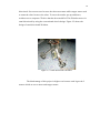
2.3.1
The Omni Directional Writobot by Muhamad Nabil bin Mansor
(2007/2008)
The omni directional writobot is omni directional vehicle that enable to
leave its trails similar to writing behavior and to point some coordinate on a surface.
Writobot is designed on three legs. Each leg is 120º apart. Each leg needs a castor
and a castor needs 2 actuators (servo and stepper motor) to makes it move in omni
11
directional. Servo motor used to steer the robot movement while stepper motor used
to rotate the wheel to move the robot. To move the marker pen up and down,
writobot uses a computer CD drive that has been modified. This Writobot moves in
omni directional by using the conventional wheels design. Figure 2.5 shows the
design of omni directional Writobot.
Figure 2.5: Omni directional Writobot
The disadvantage of this project is higher cost because each leg needs 2
motors which are servo motor and stepper motor.
12
2.3.2
Omni Directional Mobile Home Care Robot
This project is design by a group of Hsu-Chih Huang, Chia-Ming Chen, and
Tung-Sheng Wang from Department of Electrical Engineering, National ChungHsing University in 2006. This project also wins the third place in the mobile robot
contest.
The robot provides home care for the disabled and improves their quality of
life. The disabled person has to grab the article’s image in the camera and the system
directs the platform and arm to pick up the object. This robot uses 3 transwheels
design in order to move in omni directional. The transwheels are controlled by three
servo motors independently. The robot used its network camera to detect image and
robot arm to pick up objects. Figure 2.6 shows the figure of omni directional mobile
home care robot.
Figure 2.6: Omni directional mobile home care robot
13
The disadvantage of this robot is it can’t rotate the transwheels
continuously because it is driven by the servo motor. The servo motor can’t rotate
continuously, but it rotates at 180° only.
2.3.3
Moving Target Tracking of Omni Directional Robot with Stereo
Cameras
This project was done by Jun Ming Kuang, Ming Liu and Xiang Lin from
Department of Electrical and Computer Systems Engineering, Monash University,
Australia in 2006.
This robot has stereo cameras for target tracking purpose and move to the
target in omni directional. It uses 3 transwheels. The transwheels are driven by 3 DC
motors. It uses the stereo cameras to track the target and moving towards the target.
Figure 2.7 shows the figure of moving target tracking of omni directional robot with
stereo cameras.
14
Figure 2.7: Moving target tracking of omni directional robot with stereo cameras
2.3.4
Omni Directional Mobile Robot using Mecanum Wheel
This project was developed by Jefri Efendi Mohd Salih, Mohd Rizon Mohd
Juhari, Sazali Yaacob and Abdul Hamid Adom from Kolej Universiti Kejuruteraan
Utara Malaysia (KUKUM) in 2006.
The robot uses 4 custom-made mecanum wheels. The mecanum wheels
consist of nine rollers. The angle between the rollers and hub axes is 45º. All
mecanum wheels are independently controlled by 4 DC geared motor. Using 4
mecanum wheels provides omni directional vehicle without needing a conventional
steering system.
15
Depending on each individual wheel direction and speed, the resulting
combination of all these forces produce a total force vector in any desired direction,
without changing of the wheels themselves. Figure 2.8 shows the force vector of the
mecanum wheel while Figure 2.9 shows the design of omni directional mobile robot.
Figure 2.8: Force vector of mecanum wheel
Figure 2.9: Omni directional mobile robot
16
2.4
Summary of Chapter 2
The literature review done in this chapter gives more knowledge on the
omni directional movement. There are two types of special wheels, and the design
construction of the wheels. From past projects, I also discovered the advantages and
the disadvantages of this type of mobile robot. Their strengths and weakness are
compared and analyzed to discover the most appropriate specification and features to
be met in this project.
17
CHAPTER 3
METHODOLOGY
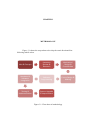
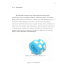
Figure 3.1 shows the steps taken to develop the omni directional line
following mobile robot.
Idea & Concept
Literature
Review &
Research
Mechanical
Design &
Construction
Hardware &
Software
Integration
Software
Programming
Circuit Design &
Making
Testing &
Implementation
System Upgrade
& Improvement
Figure 3.1: Flow chart of methodology
18
The idea comes from the earlier line following mobile robot. This project
improves the line following mobile robot by using the transwheels that has the ability
to move in omni directional. Literature review on past project was done in the
previous chapter.
The next step was designing and implementing mechanical structure of the
mobile robot base. The designing work was done by using SolidWorks software. The
design includes the base, transwheels and the DC geared motor. Continuous adaption
and improvement was made alongside this step. Figure 3.2 shows the plan, bottom
and side view of the mobile base using the SolidWorks software.
a) Plan view
b) Bottom view
19
c) Side view
Figure 3.2: View of mobile base
After that main circuit was design by using Proteus software. The circuit was
made according to the schematic drawn earlier. Later, the software part was started
whereby the C programming language was written in MPLAB IDE software.
The following step is the most important stage which is the integration
between the hardware and software that were done earlier. The validity and
feasibility of the programming codes were tested and evaluated by trial-and-error
method. Finally, the system was upgraded and improved to better the overall
performance of the omni directional line following mobile robot.
20
3.1
Hardware and Mechanical Design
The mechanical design of the base of omni directional line following mobile
robot was first being developed in FYP 1. Figure 3.3 below shows picture of
different views of the mobile robot.
Plan View
Front View
Back View
Left View
Right View
Bottom View
Figure 3.3: Different View of Mobile Base
The mobile robot base was made by 2 mm thick aluminium and radius of 110
mm. The based consists of 3 transwheels paired with 3 DC geared motor. To attach
the transwheels and the DC geared motor, a custom made coupling is needed so that
the transwheels can be driven by the DC gear motor. The transwheels are placed
120º apart.
21
12 set of IR sensors is placed at the bottom of the mobile robot. The IR sensor
is used to make the line tracking feature. There are 3 pairs of IR sensor. Each pair
consists of 4 set of IR sensor. The sensor is placed at the bottom of the mobile base.
Figure 3.4 shows the position of the IR sensor.
Figure 3.4: Position of the IR sensor
22
3.1.1
Transwheels
The Transwheel’s unique design contains eight free-turning rollers
perpendicular to the axle arranged around the Transwheel periphery. This distinct
design combined with the rotation of the wheel body provides the ability to move in
any direction without having to turn relative to the robot base. By using the
transwheels, the mobile robot can execute a single sideways motion, and further can
easily track a moving object while maintaining a required orientation with respect to
it. The advantages of mobile robot using the transwheels are allowing continuous
translation and rotation in any direction in competitive high-speed environments.
Figure 3.5 shows the picture of the transwheels.
Figure 3.5: Transwheels
23
3.1.2
DC Geared Motor (MO-SPG-30-20K)
3 DC Geared Motor were used in order to rotate the transwheels individually.
The model of the motor is MO-SPG-30-20K. I bought the motor from Cytron
Technologies. The rated voltage is DC 12V and maximum current rating is 410mA.
Additionally it stall current is 1.8 A. Furthermore, the feasible rated speed at 5200
RPM and rated torque at 5.88mNm were offered by this model of DC geared motor.
The unit price for this DC geared motor is RM 70. A pair of this product thus
costs me RM 210. Figure 3.6 show the picture of a MO-SPG-30-20K DC geared
motor.
Figure 3.6: A MO-SPG-30-20K DC geared motor
24
3.2
Electronic and Circuit Design
The first stage in electronic and circuit design is to understand the
requirements of the project and the limitation of various constraints like the level of
technology, reliability of microcontroller and the complexity of programming codes
and interfacing devices. Intensive study on electronic components’ datasheets was
then conducted to compare and analyze the advantages and shortcoming of different
electronic circuits and devices used by previous project researchers. After that, the
most reliable and suitable circuits were designed and drawn in Proteus software.
Finally, the circuit is made according to the circuit schematic designed. Subsections
below discussed the design of circuits in detail.
This project uses PIC16F777 as the main controlling unit and DC geared
motor to drive the transwheels individually. As the input, IR sensor is used. IR sensor
will detect the line in order to make the mobile robot follow the line. To control the
DC geared motor, motor driver L298N is used. Figure 3.7 shows the block diagram
of the circuit design.
IR Sensor
PIC16F777
Motor Driver L298N
Figure 3.7: Block diagram of the circuit design
25
3.2.1
PIC Start Up Kit (SK40C)
PIC Start up Kit is enhanced 40 pins PIC is designed to offer an easy to start
board for PIC. This board comes with basic element to begin project development.
By using the SK40C, it is easier to do the circuit. All the I/O pins are nicely labeled
to avoid miss-connection. It will not require extra component for the PIC to function.
The connector for UIC00A is already assembled to load program. So, it is easy to reprogramming, which is doesn’t have to plugging PIC out and back. To connect the
I/O pins, just solder SK40C to board and plugging in the I/O components. Figure 3.8
shows the picture of the SK40C.
Figure 3.8: SK40C
26
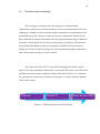
3.2.2
LiPo Battery
Lithium Polymer or LiPo battery is a type of rechargeable battery that
normally composed of several identical cells to boost up the voltage and current. One
11.1V LiPo batteries were used in this project. The model of the battery is Turnigy
Nano-Tech 11.1V, 2200 mAh, and discharge rate at 35 C. The LiPo battery was used
to drive all the circuit for my project which are PIC Start up Kit, IR sensor circuit,
and motor driver circuit to drive motor. Figure 3.9 shows the image of the LiPo
batteries that had been used.
Figure 3.9: LiPo Battery.
27
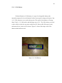
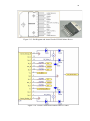
3.2.3
I/O Pin Assignation for PIC16F777
Microcontroller was used in this project due to its small sizing, low cost but
high performance. A microcontroller is combination of a microprocessor, memory,
I/O ports and other special function registers such as timer, ADC, PWM, interrupt
etc. PIC16F777 was selected as it is readily available and easy to use. Figure 3.10
shows the picture of the PIC16F777.
Figure 3.10: PIC16F777
PIC16F777 is used as the main controlling unit. It has 40 pin. It has the
program memory up to 8k single-word instructions. It has 36 I/O which are port A,
B. C. D and E. It also has 17 interrupts, 2 comparators and can control 3 PWM. This
PIC is able to be used for this project since it has to control 3 DC geared motor.
28
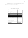
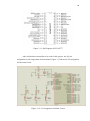
The key features of PIC16F777 can be summarized as in Table 3.1 while the
pin diagram of this microchip can be found in Figure 3.11.
Table 3.1: PIC16F777 device Features
Features
Description
Operating Frequency
DC – 20 MHz
Flash Program Memory (14-bit words) 8K
Data Memory (bytes)
368
Interrupts
17
I/O Ports
Ports A, B, C, D, E
Timers
3
Capture/Compare/PWM Modules
3
Master Serial Communications
MSSP, AUSART
Parallel Communications
PSP
10-bit Analog-to-Digital Module
14 Input Channels
Instruction Set
35 Instructions
29
Figure 3.11: Pin Diagram of PIC16F777
After decided microcontroller to be used for this project, the I/O pin
assignation for all components are determined. Figure 3.12 shows the I/O assignation
for the main circuit.
Figure 3.12: I/O Assignation for Main Circuit
30
3.2.4
Circuit Connection for DC Geared Motor’s Motor Driver L298N
Motor driver L298N is used in the main circuit as the driving chip of three
DC geared motors which provide the mobility of the mobile robot. This motor driver
allows a total of 2A high current to pass through it during operation. This complies
with the using of 12V DC geared motor. Furthermore, it is also a high voltage and
current dual full-bridge driver that was designed to accept standard TTL logic levels
and drive inductive loads such as relays, solenoids DC and even stepper motors. Two
enable inputs are provided to enable or disable the device independently of the input
signals. The emitters of the lower transistors of each bridge are connected together
and the corresponding external terminal can be used for the connection of an external
sensing resistor. An additional supply input is provided so that the logic works at a
lower voltage.
A motor driver L298N can drive up to 2 DC geared motor. Since I used 3 DC
geared motor, so I need total of 2 motor driver L298N. Figure 3.13 Shows The Pin
Diagram And Actual Look Of A L298N Motor Driver While Figure 3.14 Shows The
Circuit Connection Of L298N In The Main Circuit.
31
Figure 3.13: Pin Diagram and Actual Look of L298N Motor Driver
Figure 3.14: Circuit Connection of Motor Driver L298N
32
3.2.5
Circuit Connection of IR Sensors
Sensors used in line-tracking purpose were IR sensors which operate on the
basis of photo resistivity. An IR sensor is composed of a transmitter and a receiver.
The transmitter transmit infrared red light which is invisible for human being. The
transmitted infrared red light will be reflected by a surface and received by the
receiver. The IR receiver converts light intensity to its equivalent resistance and by
using voltage division method, the equivalent TTR logic voltage from 0V to 5V is
generated. Figure 3.15 and Figure 3.16 show the circuit design of IR sensors.
Figure 3.15: Circuit Connection of IR Sensors – Part A
33
Figure 3.16: Circuit connection of IR Sensors – Part B
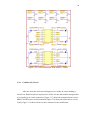
3.2.6
Combine All Circuit
After the electronic and circuit design process, hands on circuit making is
carried out. Donut board was employed for all the circuits and modules designed due
to its simplicity in circuit connection. Figure 3.17 shows the completed main circuit –
SK40C and IR sensor circuit meanwhile Figure 3.18 shows the motor driver circuit.
Lastly, Figure 3.19 shows all the circuit is mounted on the mobile base.
34
Figure 3.17: Main Circuit
Figure 3.18: Motor Driver Circuit
35
Figure 3.19: All Circuit Mounted on Mobile Base
3.3
Programming Design
After completing the hardware and the electronic circuit for the robot, the
attention was shift to programming design of the robot. The programming design of
the robot is to control its movement in omni directional. The completed programs
were then programmed into the PIC16F777 microcontrollers. Continuous debugging
and compilation of the program were needed towards the completion of the
programming design of the robot. The full programs for both controllers were
attached in the appendix of this thesis.
C-language is chosen as the programming language for this project as the
memory size needed for C-language programming is small and it is extremely easy to
36
understand. MPLAB IDE software developed by Microchip was employed to write
the C-language program. For the compilation of the program, Microchip’s C30
compiler is adopted.
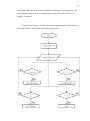
Figure 3.20 to Figure 3.21 shows the main programming flow chart and linefollowing feature of the omni line following mobile robot
37
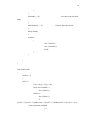
Figure 3.20: Flow Chart of Main Program
Start
Input from sensor
Data analysis
Out of
position
Yes
No
No
Need to
stop?
Yes
Stop
End
Figure 3.21: Flow Chart of Line Following
Motor’ speed and
direction
adjustment
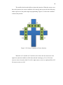
38
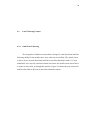
The mobile robot has the ability to detect the junction. When the sensor cross
above the junction, the sensor condition will count up and execute the line following
mode respective to the path assign in programming. Figure 3.22 show the condition
to detect the junction.
Figure 3.22: Sensor Condition to Detect Junction
When S2 or S3 and S6 or S7 and S10 or S11 above the line and receive the
signal, the junction condition will be detected and counting up. S1 to S4 is front
sensor to move forward, while S5 to S8 is right sensor to move to right and S9 to S12
left sensor to move to left.
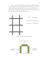
39
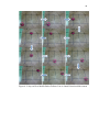
Figure 3.23 below shows the path for the line following. The line following is
already assigned to move in the respected direction. Line Following 1 is to move the
mobile robot forward, while Line Following 2 is to move the mobile robot to the
right and lastly Line Following 3 is to move the mobile robot to the right. Figure 3.24
shows the sensor for each of line following movement.
Figure 3.23: Path for the Line Following
Figure 3.24: Sensor for the Line Following
40
3.4
Summary of Chapter 3
This chapter discussed about the mechanical design, electronic and circuit
design and programming design of the Omni Directional Line Following Mobile
Robot.
In mechanical design part, the mobile robot with the specification discussed
above was successfully done. The types of motor used were also discussed in this
part. In electronic and circuit design section, various electronic components, modules
and circuits employed in this mobile robot were discussed including IR sensor, motor
driver L298N and also the main circuit of the robot.
Finally in programming part, the selection for programming tools was
determined and programming flow chart for main program and line-following of the
Omni Line Following Mobile Robot were discussed.
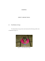
41
CHAPTER 4
RESULT AND DISCUSSION
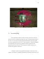
4.1
Final Hardware Design
The final hardware design of the omni directional line following mobile robot
is illustrated in Figure 4.1.
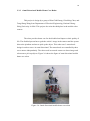
Figure 4.1: Final Hardware Design
42
The outlook of the omni directional line following mobile robot is very
compact. The mobile robot is small in size, suitable as it function to move anywhere
in small area. Table 4.1 presented the hardware specification of this mobile robot.
Table 4.1: Hardware Specification
Specification
Description
Radius
110 mm
Height
130 mm
Weight
3.0 kg
Actuators
3 DC Geared Motors
DOF
3 DOF
IR Sensor
12 IR sensors
43
4.2
Line Following Feature.
4.2.1
Omni Line Following
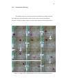
The integration of hardware and software design for omni directional and line
following ability for the mobile robot were achieved successfully. The mobile robot
is able to move in omni directional and able to track the black line made of 17 mm
width black wire tape. By omni directional movement, the mobile robot doesn’t have
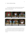
to rotate its base when go through the junction. Figure 4.2 shows the step on how the
mobile robot follows the line in omni directional movement.
44
Figure 4.2: Step on How Mobile Robot Follows Line in Omni Directional Movement
45
4.2.2
Normal Line Following.
The mobile robot also can do the normal line following. Using the normal
line following, the mobile robot needs to rotate its base when go through the
junction. To make it simple, Figure 4.3 shows the normal line following features.
Figure 4.3: Step on How Mobile Robot Follows Line in Normal Movement.
46
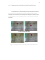
4.2.3
Comparison between Omni Directional and Normal Movement
As mention before, in omni directional movement, the mobile robot doesn’t
have to rotate its base with respect to the direction it will move. But in normal
movement, it has to rotate its base with respect to the direction it will move. Figure
4.4 will explain more about the comparison between omni directional and normal
movement.
a) Omni Directional Movement
b) Normal Movement
Figure 4.4: Comparison between Omni Directional and Normal Movement
47
When comparing in term of time taken to reach the same destination and
path, omni directional movement take less time to reach the destination, compare to
normal movement. Table 4.2 shows the time taken of the mobile robot to reach the
destination in omni directional and the normal movement.
Table 4.2: Time Taken to Reach the Destination
Reading
Omni Directional (s)
Normal (s)
1
5.59
6.85
2
5.41
6.74
3
5.89
7.32
4
5.33
6.91
5
5.74
7.01
Average
5.59
6.97
Based on the result, it is proven that omni directional takes less time to reach
the destination based on its ability to turn relative to the robot base. The smoothness
of the omni directional movement makes it more stable than the normal movement.
48
4.3
Summary of Chapter 4
This chapter discuss on the achievement of the Omni Directional Line
Following Mobile Robot. This chapter discuss on every aspect which are hardware
design and line following feature. To make it clear on what is omni directional
movement, I have compare with the normal line following. Based on the explanation
of both omni and normal line following, omni directional movement is more stable
since it can move in any direction without having to turn relative to the robot base.
49
CHAPTER 5
CONCLUSION AND RECOMMENDATION
5.1
Conclusion
This project had effectively move in omni directional movement and at the
same time can track black line and follow the black line in particular direction that
has been assign to. It can be concluded that all the objectives in Chapter 1 are
achieved by the end of this research. The Omni Directional Line Following Mobile
Robot able to move in omni directional and follow the black line given.
50
5.2
Problem
During completing Omni Directional Line following Mobile Robot, there
were several problems occurs.
First problem is to define omni directional movement. Because the movement
is depending on the total vector by each transwheels, I have to find the movement
algorithm. I have difficulties because of the unique position of transwheels which is
120° apart. I take more time to find the algorithm. I need to try and error until I get
the right movement.
Last problem is to place the IR sensor so it will detect the black line and
follow the black line. Total of 12 pair IR sensor is used in order to enable the line
following ability. The problem is not on the line following movement, but the main
problem is how it will detect the line and respond by moving in omni directional.
From 12 pair of sensor, I divided it into 3 set of sensor; each set will have 4 pair of
IR sensor.
Based on the 3 set of IR sensor, first idea, I make it in triangular shape. But it
is not effective since I can’t make it to move in omni directional. So I do the second
idea, which is in square shape. Because I only have 3 set of sensor, so the square
shape is incomplete. I remove the IR sensor at the bottom. The sensor placement can
be referred at Figure 3.4. The sensor can detect the junction and can follow the black
line.
51
5.3
Limitation
The mobile robot can detect cross junction only. Otherwise it will move in
normal line following. The mobile robot has to detect the junction condition first and
then it will process the next movement. Lastly the movement is already assigned in
the programming based on the path given. So to move in other path, I have to
reprogram based on the new movement I want.
5.4
Recommendation
For future development, it is recommended to use 4 transwheels design
instead of 3 transwheels design. Using 4 transwheels design, its movement is more
stable. Moreover, it is easier to find the movement algorithm. Another
recommendation is to put position sensor like compass or gyro sensor. So this mobile
robot has a reference relative to its base. To move, it doesn’t have to rotate but only
translate with respect to degree of the given point.
52
REFERENCES
1. Jefri Efendi Mohd Salih, Mohd Rizon Mohd Juhari, Sazali Yaacob and Abdul
Hamid Adom. A Design of Omni Directional Mobile Robot. Bachelor Thesis.
KUKUM; 2006
2. Mohd Solehin Bin Shamsudin. Multi Directional Mecanum Robot. Bachelor
Thesis. Universiti Teknologi Malaysia; 2007
3. Naveen Suresh Kuppuswamy, Se-Hyoung Cho, Daniel Stonier, Sung-Lok
Choi and Jong-Hwan Kim. Design of an omni directional robot for FIRA
ROBOSOT. Korea Advance Institute of Science and Technology; 2006
4. Muhamad Nabil bin Mansor. The Omni Directional Writobot. Bachelor
Thesis. Universiti Teknologi Malaysia; 2007
5. Hsu-Chih Huang, Chia-Ming Chen and Tung-Sheng Wang. Omni Directional
Mobile Home Care Robot. Department of Electrical Engineering, National
Chung-Hsing University; 2006
6. Jun Ming Kuang, Ming Liu and Xiang Lin. Moving Target Tracking of Omni
Directional Robot with Stereo Camera., Department of Electrical and
Computer Systems Engineering, Monash University, Australia; 2006
7. PIC16F777 Microcontroller User Manual, 2006
8. L298 datasheet, 2000
9. http://www.youtube.com/
10. http://www.wikipedia.org/
53
APPENDIXES
APPENDIX A: Source Code for Omni Directional Line Following Mobile Robot
#include <pic.h>
//
configuration
//===========================================================
===============
__CONFIG(0x3FA2);
__CONFIG(0x3FBC);
unsigned char i=0,shift=0;
int j=0;
unsigned int k=0;
//
define
//===========================================================
===============
#define button1
RB0
#define button2
RB1
#define sen1
RD0
#define sen2
RD1
#define sen3
RD2
#define sen4
RD3
#define sen5
RD4
//sensor array back motor
//sensor array left motor
54
#define sen6
RD5
#define sen7
RD6
#define sen8
RD7
#define sen9
RA2
#define sen10
RA3
#define sen11
RA4
#define sen12
RA5
#define led1
RB6
#define led2
RB7
//sensor array right motor
#define lmspeed
CCPR1L
#define lmotor1
RC0
#define lmotor2
RC3
#definermspeed
CCPR2L
#define rmotor1
RC4
#define rmotor2
RC5
#definebmspeed
CCPR3L
#define bmotor1
RB3
#define bmotor2
RB4
//
function prototype
//===========================================================
===============
void m_stop(void);
void lm_run(unsigned char dir);
void rm_run(unsigned char dir);
void bm_run(unsigned char dir);
void clockwise(void);
void anticlockwise(void);
void delay(unsigned long data);
55
void line_follow1(void);
void line_follow2(void);
void line_follow3(void);
void omni1(void);
void normal1(void);
void forward1(void);
void left1(void);
void right1(void);
void sharpleft1(void);
void sharpright1(void);
void forward2(void);
void left2(void);
void right2(void);
void sharpleft2(void);
void sharpright2(void);
void forward3(void);
void left3(void);
void right3(void);
void sharpleft3(void);
void sharpright3(void);
//
main function
(main fucntion of the
program)
//===========================================================
===============
void main(void)
{
//setup ADC
ADCON1 = 0b00001111;
//set I/O input output
56
TRISA = 0b00111100;
TRISB = 0b00000011;
TRISC = 0b00000000;
TRISD = 0b11111111;
PORTA = 0;
PORTB = 0;
PORTC = 0;
PORTD = 0;
PORTE = 0;
//Setup up PWM operation
PR2=255;
CCP1CON = 0b00001100;
CCP2CON = 0b00001100;
CCP3CON = 0b00001100;
T2CON = 0b00000100;
lmspeed = 0;
rmspeed = 0;
bmspeed = 0;
//program start
while(1)
{
if(button1 == 0)
//select mode
{
i+=1;
//local variable i
plus one
if(i==)i=0;
//when local variable i
reach three,set it back to zero
while(button1 == 0)
{
delay(10000);
//loop to filter the switch
57
}
}
if(button2 == 0)
//execute to the selected
mode
{
while(button2 == 0)
//loop to filter the switch
{
delay(10000);
}
switch(i)
{
case 1:omni1();
case 2:normal1();
break;
}
}
}
}
void omni1(void)
{
while(i==1)
{
led1^=1;
if ((j==0)||(j==2)||(j==4)){
for(k=0;k<10000;k++)
line_follow1();
while(1){
line_follow1();
if
(((sen2==1)||(sen3==1))&&((sen6==1)||(sen7==1))&&((sen10==1)||(sen11==1))){
//sensor junction condition
j++;
58
m_stop();
break;
}
}
}
if ((j==1)||(j==5)){
for(k=0;k<10000;k++)
line_follow3();
while(1){
line_follow3();
if
(((sen2==1)||(sen3==1))&&((sen6==1)||(sen7==1))&&((sen10==1)||(sen11==1))){
j++;
m_stop();
break;
}
}
}
if ((j==3)){
for(k=0;k<10000;k++)
line_follow2();
while(1){
line_follow2();
if
(((sen2==1)||(sen3==1))&&((sen6==1)||(sen7==1))&&((sen10==1)||(sen11==1))){
j++;
m_stop();
break;
}
}
}
if(j==6)
{
59
for(k=0;k<10000;k++)
m_stop();
}
}
}
void normal1(void)
{
while(i==2)
{
led2^=1;
if ((j==0)||(j==3)||(j==4)){
for(k=0;k<10000;k++)
line_follow1();
while(1){
line_follow1();
if
(((sen2==1)||(sen3==1))&&((sen6==1)||(sen7==1))&&((sen10==1)||(sen11==1))){
j++;
m_stop();
lmspeed=rmspeed=bmspeed=200;
lm_run(0);
rm_run(0);
bm_run(0);
delay(30000);
break;
}
}
}
if ((j==1)||(j==2)){
for(k=0;k<10000;k++)
line_follow1();
60
while(1){
line_follow1();
if
(((sen2==1)||(sen3==1))&&((sen6==1)||(sen7==1))&&((sen10==1)||(sen11==1))){
j++;
m_stop();
lmspeed=rmspeed=bmspeed=200;
lm_run(1);
rm_run(1);
bm_run(1);
delay(30000);
break;
}
}
}
if ((j==5)){
for(k=0;k<10000;k++)
line_follow1();
while(1){
line_follow1();
if
(((sen2==1)||(sen3==1))&&((sen6==1)||(sen7==1))&&((sen10==1)||(sen11==1))){
j++;
m_stop();
break;
}
}
}
if(j==6)
{
for(k=0;k<10000;k++)
m_stop();
}
61
}
}
//line following 1 mode
//===========================================================
========================================================
void line_follow1(void)
{
unsigned char memory;
if((sen4==0)&&(sen3==0)&&(sen2==0)&&(sen1==1))
//0001
{sharpright1();memory = PORTD&0b11111111;}
else if((sen4==0)&&(sen3==0)&&(sen2==1)&&(sen1==0))
//0010
{right1();memory = PORTD&0b11111111;}
else if((sen4==0)&&(sen3==0)&&(sen2==1)&&(sen1==1))
//0011
{right1();memory = PORTD&0b11111111;}
else if((sen4==0)&&(sen3==1)&&(sen2==0)&&(sen1==0))
//0100
{left1();memory = PORTD&0b11111111;}
else if((sen4==0)&&(sen3==1)&&(sen2==1)&&(sen1==0))
//0110
{forward1();memory = PORTD&0b11111111;}
else if((sen4==1)&&(sen3==0)&&(sen2==0)&&(sen1==0))
//1000
{sharpleft1();memory = PORTD&0b11111111;}
62
else if((sen4==1)&&(sen3==1)&&(sen2==0)&&(sen1==0))
//1100
{left1();memory = PORTD&0b11111111;}
else if((sen1==0)&&(sen2==0)&&(sen3==0)&&(sen4==0))
//0000
{
if ((memory == 0b00000001)||(memory ==
0b00000011)||(memory == 0b0000010))
{
sharpright1();
}
else if ((memory == 0b00001000)||(memory ==
0b00000100)||(memory == 0b00001100))
{
sharpleft1();
}
}
}
//line following 2 mode
//===========================================================
========================================================
void line_follow2(void)
{
unsigned char memory;
if((sen8==0)&&(sen7==0)&&(sen6==0)&&(sen5==1))
//0001
{sharpright2();memory = PORTD&0b11111111;}
63
else if((sen8==0)&&(sen7==0)&&(sen6==1)&&(sen5==0))
//0010
{right2();memory = PORTD&0b11111111;}
else if((sen8==0)&&(sen7==0)&&(sen6==1)&&(sen5==1))
//0011
{right2();memory = PORTD&0b11111111;}
else if((sen8==0)&&(sen7==1)&&(sen6==0)&&(sen5==0))
//0100
{left2();memory = PORTD&0b11111111;}
else if((sen8==0)&&(sen7==1)&&(sen6==1)&&(sen5==0))
//0110
{forward2();}
else if((sen8==1)&&(sen7==0)&&(sen6==0)&&(sen5==0))
//1000
{sharpleft2();memory = PORTD&0b11111111;}
else if((sen8==1)&&(sen7==1)&&(sen6==0)&&(sen5==0))
//1100
{left2();memory = PORTD&0b11111111;}
else if((sen5==1)&&(sen6==1)&&(sen7==1)&&(sen8==1))
//1111
{forward2();}
else if((sen5==0)&&(sen6==0)&&(sen7==0)&&(sen8==0))
//0000
{
m_stop();
}
64
}
//line following 3 mode
//===========================================================
========================================================
void line_follow3(void)
{
unsigned char memory;
if((sen9==0)&&(sen10==0)&&(sen11==0)&&(sen12==1))
//0001
{sharpright3();memory = PORTA&0b00111100;}
else if((sen9==0)&&(sen10==0)&&(sen11==1)&&(sen12==0))
//0010
{right3();memory = PORTA&0b00111100;}
else if((sen9==0)&&(sen10==0)&&(sen11==1)&&(sen12==1))
//0011
{sharpright3();memory = PORTA&0b00111100;}
else if((sen9==0)&&(sen10==1)&&(sen11==0)&&(sen12==0))
//0100
{left3();memory = PORTA&0b00111100;}
else if((sen9==0)&&(sen10==1)&&(sen11==1)&&(sen12==0))
//0110
{forward3();}
else if((sen9==1)&&(sen10==0)&&(sen11==0)&&(sen12==0))
//1000
65
{sharpleft3();memory = PORTA&0b00111100;}
else if((sen9==1)&&(sen10==1)&&(sen11==0)&&(sen12==0))
//1100
{sharpleft3();memory = PORTA&0b00111100;}
else if((sen9==1)&&(sen10==1)&&(sen11==1)&&(sen12==1))
//1111
{forward3();}
else if((sen9==0)&&(sen10==0)&&(sen11==0)&&(sen12==0))
//0000
{
m_stop();
}
}
// Motor Control function
//===========================================================
===============
void m_stop(void)
{
lmotor1=0;
lmotor2=0;
rmotor1=0;
rmotor2=0;
bmotor1=0;
bmotor2=0;
}
66
void lm_run(unsigned char dir)
{
lmotor1=dir;
lmotor2=!dir;
}
void rm_run(unsigned char dir)
{
rmotor1=dir;
rmotor2=!dir;
}
void bm_run(unsigned char dir)
{
bmotor1=!dir;
bmotor2=dir;
}
void clockwise(void)
{
lmspeed=rmspeed=bmspeed=255;
lm_run(1);
rm_run(1);
bm_run(1);
}
67
void anticlockwise(void)
{
lmspeed=rmspeed=bmspeed=255;
lm_run(0);
rm_run(0);
bm_run(0);
}
//line following 1
//===========================================================
==============================================
void forward1(void)
{
lmspeed=rmspeed=230;
bmspeed=0;
lm_run(0);
rm_run(1);
}
void right1(void)
{
lmspeed=180;
rmspeed=216;
bmspeed=180;
lm_run(0);
rm_run(1);
bm_run(1);
}
void left1(void)
{
rmspeed=180;
lmspeed=216;
68
bmspeed=180;
lm_run(0);
rm_run(1);
bm_run(0);
}
void sharpleft1(void)
{
lmspeed=220;
rmspeed=220;
bmspeed=220;
lm_run(0);
rm_run(0);
bm_run(0);
}
void sharpright1(void)
{
lmspeed=220;
rmspeed=220;
bmspeed=220;
lm_run(1);
rm_run(1);
bm_run(1);
}
//line following 2
//===========================================================
==============================================
void forward2(void)
{
lmspeed=180;
69
rmspeed=180;
bmspeed=240;
lm_run(0);
rm_run(0);
bm_run(1);
}
void right2(void)
{
lmspeed=0;
rmspeed=200;
bmspeed=220;
rm_run(0);
bm_run(1);
}
void left2(void)
{
lmspeed=220;
rmspeed=0;
bmspeed=220;
lm_run(0);
bm_run(1);
rm_run(0);
}
void sharpleft2(void)
{
lmspeed=200;
rmspeed=200;
bmspeed=200;
70
lm_run(0);
rm_run(0);
bm_run(0);
}
void sharpright2(void)
{
lmspeed=200;
rmspeed=200;
bmspeed=200;
lm_run(1);
rm_run(1);
bm_run(1);
}
//line following 3
//===========================================================
==============================================
void forward3(void)
{
lmspeed=180;
rmspeed=180;
bmspeed=240;
lm_run(1);
rm_run(1);
bm_run(0);
}
void right3(void)
{
lmspeed=0;
rmspeed=220;
71
bmspeed=220;
rm_run(1);
bm_run(0);
}
void left3(void)
{
lmspeed=220;
rmspeed=0;
bmspeed=220;
lm_run(1);
bm_run(0);
rm_run(0);
}
void sharpleft3(void)
{
lmspeed=200;
rmspeed=200;
bmspeed=200;
lm_run(0);
rm_run(0);
bm_run(0);
}
void sharpright3(void)
{
lmspeed=200;
rmspeed=200;
bmspeed=200;
lm_run(1);
rm_run(1);
72
bm_run(1);
}
//
delay functions
//===========================================================
===============
void delay(unsigned long data)
{
for( ;data>0;data-=1);
}