1
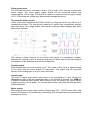
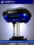
4 Channel
Motor Control Unit
Designed originally for the Rover 5 chassis this driver PCB is ideal for any small robot
using either Omni or Mecanum wheels. Current sensing for each motor allows the
processor to determine if a motor has stalled or is under excessive load.
Features include:
•
•
•
•
•
4x low resistance FET “H” bridges.
Each channel rated for 4A stall current.
Easy to use control logic.
Current monitoring for each channel.
Quadrature encoder mixing circuitry.
Power connectors:
The PCB has two power connectors. One is +5V for logic (Vcc) and one for the motor
power supply. The motor power supply should not be connected without first
connecting the +5V for logic. This device is rated for a maximum motor supply voltage
of 12V. Exceeding this voltage may permanently damage the device.
The encoder mixing circuit:
Unlike most motor controllers this PCB includes 4 mixing circuits for use with up to 4
quadrature encoders. The mixing circuit takes the 2 inputs from a quadrature encoder
and mixes them into a single output. Note that the interrupt output changes state when
either input changes.
This allows a single interrupt pin to monitor both inputs of a quadrature encoder.
Because the interrupt output is twice the frequency of either input it also allows speed
and distance to be measured with twice the resolution.
Current output:
Each channel has a current sensing circuit. The output of this circuit is approximately
1V for each amp the motor draws (5V maximum). This output can be connected
directly to the analog input of any 5V micro controller.
Control logic:
The built in control logic allows each motor to be controlled by 2 pins. Driving the
direction pin high or low will cause the motor to run forward or reverse. The PWM pin
is used to control the motor speed. When this pin is low, the motor is off. When this pin
is high the motor is at full power. To vary the speed of the motor this pin must be Pulse
Width Modulated.
Motor output:
Each channel has a motor output socket. Connect any 4.5V –12V DC motor with a stall
current of less than 4.5A to these pins. Exceeding 4.5A on these pins may permanently
damage this device.