1
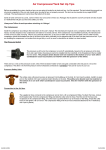
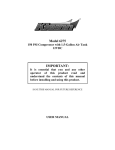
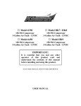
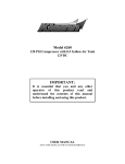
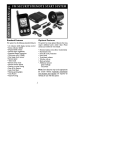
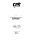
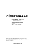
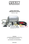
Model 6350RC 100% Duty Cycle Compressor IMPORTANT: It is essential that you and any other operator of this product read and understand the contents of this manual before installing and using this product. USER MANUAL SAVE THIS MANUAL FOR FUTURE REFERENCE Model 6350RC Components: 1 Model 6350RC Kleinn Air Compressor (Please check to make sure that you have three labeled packages in your kit. Each package contains the parts needed for specific areas of onboard air installation, and may contain smaller bags within each package labeled for specific use.) PARTS PACKAGES Package #4 – Compressor & Tank Installation Qty 4 13/64” Nuts, shorter bolts, washers & locking washers (Compressor mounting hardware) Qty 1 Remote Mount Air Filter Assembly Qty 1 Remote Mount air filter fittings Qty 1 Replacement air filters Qty 1 Leader Hose Bracket Clip Qty 1 Air line for remote mounting air filter Air Compressor Installation CAUTION - To reduce risk of electrical shock or electrocution: Do not disassemble the compressor. Do not attempt repairs or modifications. Refer to qualified service agencies for all service and repairs. Do not use this product in an area where it can fall or be pulled into water or liquids. Do not reach for this product if it has fallen into liquid. Use this compressor with 12-volt DC systems only. This product should never be left unattended during use. Guidelines for Selecting Mounting Location: The selection of proper mounting location for your air compressor will help ensure a long and trouble free compressor service life. Please pay close attention to the following: Select a flat and secure location where the compressor can be mounted. The 6350RC can be mounted in any position; however, we do not recommend mounting it upside down, as this can cause excessive heat build-up. To maximize air compressor performance, locate compressor as close to the battery as possible so that length of positive lead wire required is at a minimum. Choose mounting location that is as cool as possible and away from heat sources. This compressor is moisture & dust resistant, but NOT WATERPROOF or DUST PROOF. Do not mount compressor in locations such as behind a tire, where the unit is likely to come in contact with excessive water or dirt. The compressor may be mounted underneath your vehicle as long as you use the remote air intake kit that is included with the system and relocate the air intake. When using the remote intake, select compressor’s mounting location where air line can be routed from compressor air inlet to remote inlet air filter. Make sure that the remote inlet air filter is located in a dry location, away from water. You will also want to select a compressor mounting location where the leader hose bracket can be mounted to secure the stainless steel braided leader hose. If it is necessary to mount the air compressor further from the battery, such as inside your vehicle or in the bed of your pickup, use a minimum 8 AWG positive lead wire for remote installation. Do not mount compressor near areas where flammable liquids are stored. Compressor Wiring: 1. Disconnect ground cable from vehicle’s battery. 2. Temporarily position the air compressor in the location where it will be mounted. 3. Route ground wire to the negative post of the battery or to an appropriate grounding point and cut ground wire to length as needed. 4. Mount the air compressor with the four sets of 13/64” (5 mm) bolts, nuts, washers, and locking washers provided. Use of thread locker is recommended. 5. NOTE: For Remote Inlet Air Filter Installation, use all components included in the Remote Inlet Air Filter Pack. 6. This air compressor comes with a heavy duty heat resistant stainless steel braided leader hose with ¼” NPT fittings. This leader hose is designed to prolong the life of your air line. Do not remove this leader hose from air compressor. 7. IMPORTANT: Please note; the leader hose that came with your compressor has a built-in inline check valve. Do not remove inline check valve from leader hose. 8. Select a proper location to mount leader hose with hose bracket provided. Avoid locations where leader hose may become tangled with wires and other hoses. 9. To mount hose bracket, drill holes with 3/16” drill bit and push self–anchoring hose bracket pin into hole. Route leader hose through hose bracket and secure hose by pressing bracket clamp into locked position. 10. To remove hose from the hose bracket, simply press down on the hose clamp release tab to release bracket clamp. 11. Connect compressor’s positive lead wire to one of the leads of your pressure switch. 12. Make sure that your compressor setup is properly fused. The compressor pulls approximately 16 amps of power maximum. 13. Always locate fuse as close as possible to power source. 14. Before connecting to power source, check to make sure that all connections are made properly. 15. Connect and test compressor system by running the compressor for a short time to build up pressure in your air tank. 16. Once air pressure reaches the preset cut out pressure of your pressure switch, the compressor will shut off. Inspect all air line connections for leaks with soap and water solution. If a leak is detected, the air line may not be cut squarely or pushed all the way in. Tighten connections if needed. 17. Always use a “switched” power source that only supplies power to your compressor when the vehicle is running. COMPRESSOR OPERATING INSTRUCTIONS IMPORTANT: The compressor has a maximum working pressure of 150 PSI and is capable of 100% duty cycle. It is designed for use with air horns, air bags and other accessories that utilize the compressed air stored in the tank. It is not designed for continuous use applications such as tire inflation or air tools. Always operate the compressor at or below the MAXIMUM PRESSURE RATING of the compressor (150 PSI). Operation exceeding maximum pressure ratings and or duty cycle will result in damage to air compressor. 1. Your air compressor is equipped with an AUTOMATIC THERMAL OVERLOAD PROTECTOR. This feature is designed to protect the air compressor from overheating and causing permanent damage to your air compressor. The thermal overload protector will automatically cut off power to your air compressor should the internal operating temperature of the air compressor rise above safe levels during excessive use. 2. Should your air compressor automatically shut off while in use; do not attempt to restart the air compressor. Turn power switch to the air compressor to the OFF position. The automatic thermal overload protector will automatically reset when internal temperature of the air compressor drops below safe level. After allowing air compressor to cool off for about 30 minutes, you can safely resume use of the air compressor by turning on the air compressor. 3. To prevent discharge of your vehicle’s battery and to provide peak performance, we strongly recommend that you keep the vehicle’s engine running while using the air compressor. 4. ONLY OPERATE THE AIR COMPRESSOR IN WELL-VENTILATED AREAS. Compressor Maintenance & Repairs 1. Periodically check all electrical and fitting connections. Clean / tighten as needed. 2. Periodically check all mounting hardware. Tighten as needed. 3. Replace air filter element periodically. Replacement frequency depends on operating frequency and operating environment. For frequent use in dusty environment, you should replace air filter element more frequently. 4. Regularly clean dust and dirt from compressor. 5. Your air compressor is equipped with permanently lubricated, maintenance free motor. Never lubricate the compressor. 6. Repairs should be performed by Manufacturer or Manufacturer’s Authorized Service Agencies only. CAUTION: Never touch the air compressor or fittings connected to the air compressor with bare hands during or immediately after use. Leader hose and fittings will become very HOT during and after use. Compressor Installation Tips 1. Use the remote intake filter option whenever possible. This will extend the service life of your compressor. 2. If noise reduction from vibration is desired, using the remote mount option for the inlet filter can reduce operation noise by up to 25%. 3. Always mount the compressor at a point higher than the inlet port of the tank. This will keep moisture from being able to seep back to the tank. 4. When mounting the compressor, use a paint pen on the rubber isolators. Then, simply stamp the compressor against the chassis to make an imprint of exactly where to drill the mounting holes for the compressor. Pressure Switch Installation Your system requires the use of a pressure switch that will turn the compressor on & off. The use of a 40-amp, 4-post relay is strongly suggested to prolong the pressure switch life span. The 6350RC air compressor is rated to 150 PSI maximum working pressure. Wire the air compressor like this: Pressure Switch & Relay Installation Tips 1. Never install a pressure switch in direct line from the inlet port coming from the compressor. Tank pressure can be misread by the pressure switch. Instead, mount the pressure switch on the tank where it receives readings from deflected air in the tank. 2. Never use a pressure switch that is rated beyond your compressor’s rated Maximum Working Pressure (150 PSI). 3. Always use a relay to turn the compressor on and off. This will increase the life of the pressure switch. (Note: Relay wiring diagram above.) 4. Each lead of the pressure switch is a (+) power lead. One lead is connected to the power lead on your compressor, and the other is routed to a fused, switched power. Testing Your System Your system installation is now complete. Run the compressor to build pressure in the air tank. When air pressure reaches the pressure switch cut out pressure, the compressor will shut off. Inspect all air line connections for leaks by spraying a soap and water solution on them and looking for bubbles. If leaks are detected, re-attach hoses or apply Teflon thread tape as needed. Periodically check your system’s fitting in this manner should your compressor turn on more often than normal without frequent air use. When Installing This Air Compressor For Use with Air Horns: When installing for use with air horns, the air compressor system and horns are considered to be TWO SEPARATE SYSTEMS. The only thing that connects the two systems is the air line that supplies the air solenoid attached to the air horn. Installing Air Horn Solenoid: Note: the solenoid valve must NOT be connected to the relay used in the air system. To wire the horn solenoid for use, select one of the wires on the air horn solenoid and ground it. The second wire will be routed to the button that you will use to honk the air horn. On the back of the horn button, there will be another terminal. The second terminal must be routed to 12-volt power and fused at 5 amps at the battery of the vehicle. KLEINN MANUFACTURER LIMITED DEFECT WARRANTY: Kleinn Automotive warrants this product to the end-user, when properly installed and under normal conditions of use, to be free from defects in workmanship and materials for a period of one year from the provided date of purchase, to the original purchaser of the product. This warranty does not cover abuse, operation in a manner inconsistent with the product’s design, or damage resulting from exposure to the elements. If the defect is considered “under warranty”, Kleinn Automotive will, at its option, repair or replace the product free of charge to the original purchaser. Kleinn Automotive is not liable for any installation charges, loss or damage of any kind incurred in the replacement, repair of any warranted product. Kleinn Automotive Accessories P.O. Box 91278 Tucson, AZ 85752 (520) 579-1531 [email protected]