1
5. UNDERNEATH AQUARIUM WITH A CANISTER FILTER
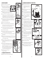
5A.Place filter in desired location next to the canister filter. Position the filter so
5A.
that it can be plumbed on the outlet side of the canister filter. In steps 5B
through 5E, refer to installation drawings in section #2 (Beside The Aquarium).
5B.Screw in the plugs on each side of the bottom manifold. Make sure the plug
“o” rings are seated properly. In most cases, the bottom inlet ports will not
be needed in this type of installation.
5C. Screw in the check valve assembly in top inlet port. Make sure check valve
“o” ring is seated properly.
5D.Wrap thread seal tape on the male threads of the two 3/4” MPT x 1/2” barb
elbow fittings provided. Wrap each fitting 5-7 times with thread seal tape.
5E. Screw one 3/4” MPT x 1/2” barb elbow fitting into the check valve assembly located at the top inlet port.
Screw in the other elbow fitting into the outlet port located at the top of the unit.
5G.Turn off the valve on the outlet side of the canister filter and completely drain the flexible tubing on the outlet
side of the canister filter. In most cases, it will be necessary to remove the “U” or “J” tube from the back of the aquarium. Cut the flexible tubing on the outlet side of the canister filter and plumb in line a by-pass valve and “tee” which will divert only a portion of the water from the canister filter and into the inlet port on the left side of the top manifold. Attach hose clamps and tighten accordingly.
5H.Attach one end of the 1/2” ID x 11/16” OD flexible tubing to the 3/4” MPT x 1/2” barb elbow located at the top
outlet side of the filter. Attach hose clamps and tighten accordingly.
5I. Place the other end of the tubing up and over the side or back of the aquarium so that the water returns to the aquarium and agitates the surface to aerate the system. In some cases, flexible tubing can be attached to a rigid plastic “U” or “J” tube (not supplied in this unit) that hangs on the aquarium. Attach hose clamps to the rigid tube and tighten accordingly.
5J. Add media to the unit by following steps H, I, J, K, and L in section #1 (Hanging On The Aquarium).
5K.Open the by-pass valve completely.
5L. Carefully adjust the fluidization level by following steps P, Q, and R in section #1(Hanging On The Aquarium).
5M.Partially close the by-pass valve to direct more water into the
filter only if proper fluidized is not achieved.
6A.
6. CONNECTING MULTIPLE UNITS TOGETHER
6A.Place each filter in desired location next to the aquarium system. Make sure
unit is level on base. If it’s more desirable to hang the filters on the side or
back of a aquarium or reservoir tank, please refer to steps E, F, and G in
section #1 (Hanging On The Aquarium).
6B. Screw in plug into the top inlet port on each filter. Screw in another plug into
the bottom inlet port on the right side of the last filter in line and the left side
of the first filter in line. Make sure the plug “o” rings are seated properly.
6C. Screw in check valve assembly into the inlet port on the right side of the
bottom manifold of first filter and the left side of the next filter.
6D. Wrap thread seal tape on the male threads of the two 3/4” MPT x 1/2” barb elbow fittings. Wrap each fitting 5-7 times with tape.
6E. Screw each of the 3/4” MPT x 1/2” barb elbow fittings into the outlet ports on the top side of
each filter. Position the barb portion of the fitting straight up vertically.
6
6F. Attach one end of the 1/2” ID x 11/16” OD flexible tubing to the 3/4” MPT x 1/2” barb elbow located at the top outlet side of the filter. Place the other end of the tubing up and over the side or back of the aquarium so that the water returns to the aquarium and agitates the surface to aerate the system. In some cases, flexible tubing can be attached to a rigid plastic “U” or “J” tube (not supplied in this unit) that hangs on the aquarium. Repeat this for each filter used. Attach hose clamps where needed and tighten accordingly.
6G. A by-pass valve may be needed depending on what size pump is used. The by-pass valve will divert only a
portion of the water from the pump to the filters. Refer to step 4E in section #4 (Underneath Aquarium with a Lifegard System).
6H. Add media to each filter by following steps H, I, J, K, L, in section #1 (Hanging On The Aquarium).
6I. Open by-pass valve completely.
6J. Carefully adjust the fluidization level of each filter by following the steps P, Q and R in section #1 (Hanging On The Aquarium).
6K. Partially close the by-pass valve to divert more water into the filters only if proper fluidization is not achieved.
ADDING REPLACEMENT MEDIA
Hanging Installations
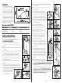
A. Turn off pump and wait a full 10 minutes for the media to settle into the bottom chamber. If you have lost media, the level of the media will be below the “Media Fill Level” label located on the right side of the clear chamber.
B. Remove the retainer screws from the flow control valve located at the top outlet side of the filter.
C. Pull the flow control valve straight up and remove.
D. Pour in the media up to the “Media Fill Level” label on the unit. Wipe off any media that may be in the valve chamber
with a dry cloth. Lubricate the valve and valve chamber with
the Lifegard silicone lubricant supplied with the unit.
E. Install the flow control valve back into the valve chamber
making sure the “o” ring is seated properly and all parts are free of any debris or media.
F. Screw in the two valve retainer screws.
Below Tank Installations
A. Turn off pump to Lifegard Modular System or canister filter.
B. Completely drain flexible tubing on the outlet side of fluidized bed filter.
C. Follow steps A, B, C, D, E, and F in the above section (Adding
Replacement Media, Hanging Installations).
ADDITIONAL EQUIPMENT REQUIRED
Additional equipment is needed in order to achieve optimal
water quality in your aquarium. This is vital to the health of
your plants and animals as well as the nitrifying bacteria in your
fluidized bed filter. Accumulation of large amounts of particulate
and dissolved organic material will encourage the growth of
other types of bacteria (heterotrophic) that will compete
with the nitrifying bacteria for available space and nutrients.
Additional equipment needed to reduce this accumulation of
particulate and dissolved organic material will include
the following:
A. MECHANICAL FILTRATION
This type of filter will trap and remove floating debris and should be cleaned routinely. A prefilter sponge should be attached to the pump to trap debris before it enters the fluidized bed filter.
B. CHEMICAL FILTRATION
This type of filter is usually filled with activated carbon that removes dissolved organic molecules.
C. AERATION
Additional aeration equipment is needed in order to
maintain complete oxygen saturation in your aquarium
system. This can be achieved with an air pump and diffuser as well as good water movement at the surface of the
aquarium. Proper circulation is necessary in order to achieve oxygen saturation in your aquarium.
D. ULTRAVIOLET STERILIZATION
Ulrtaviolet sterilizers control the transmission of
disease from one fish to another by killing free floating
micro-organisms as they pass through the unit. The
nitrifying bacteria are not killed because they are attached
to the media within the fluidized bed filter and are not free
floating. Ultraviolet sterilizers, although optional, should be the final stage of your filtration system.
pH LEVEL
Nitrifying bacteria produce acids when utilizing the ammonia
and nitrite in the water. These acids decrease the pH in the
aquarium and will inhibit the nitrification process when this
value drops below an acceptable level. This will lead to a
dangerous build up of ammonia! It is therefore vital that the
pH be tested weekly and a proper level is maintained in the
aquarium. Please contact the dealer in your area for advice in
recommending the proper additive for maintaining the
optimum pH level.
Recommended levels:
pH............................ fresh water................. above 6.2 salt water................... 8.2 - 8.4
7