1
User Guide
TCM2.5 & TCM2.6
© Copyright PNI Sensor Corporation 2005
All Rights Reserved. Reproduction, adaptation, or translation without prior written permission is prohibited, except
as allowed under copyright laws.
Revised July 2013. For most recent version visit our website at www.pnicorp.com
PNI Sensor Corporation
2331 Circadian Way
Santa Rosa, CA 95407 USA
Tel: (707) 566-2260
Fax: (707) 566-2261
Warranty and Limitation of Liability. PNI Sensor Corporation ("PNI") manufactures its TCM products (“Products”)
from parts and components that are new or equivalent to new in performance. PNI warrants that each Product to be
delivered hereunder, if properly used, will, for one year following the date of shipment unless a different warranty
time period for such Product is specified: (i) in PNI’s Price List in effect at time of order acceptance; or (ii) on PNI’s
web site (www.pnicorp.com) at time of order acceptance, be free from defects in material and workmanship and will
operate in accordance with PNI’s published specifications and documentation for the Product in effect at time of
order. PNI will make no changes to the specifications or manufacturing processes that affect form, fit, or function of
the Product without written notice to the OEM, however, PNI may at any time, without such notice, make minor
changes to specifications or manufacturing processes that do not affect the form, fit, or function of the Product. This
warranty will be void if the Products’ serial number, or other identification marks have been defaced, damaged, or
removed. This warranty does not cover wear and tear due to normal use, or damage to the Product as the result of
improper usage, neglect of care, alteration, accident, or unauthorized repair.
THE ABOVE WARRANTY IS IN LIEU OF ANY OTHER WARRANTY, WHETHER EXPRESS, IMPLIED, OR
STATUTORY, INCLUDING, BUT NOT LIMITED TO, ANY WARRANTY OF MERCHANTABILITY,
FITNESS FOR ANY PARTICULAR PURPOSE, OR ANY WARRANTY OTHERWISE ARISING OUT OF ANY
PROPOSAL, SPECIFICATION, OR SAMPLE. PNI NEITHER ASSUMES NOR AUTHORIZES ANY PERSON
TO ASSUME FOR IT ANY OTHER LIABILITY.
If any Product furnished hereunder fails to conform to the above warranty, OEM’s sole and exclusive remedy and
PNI’s sole and exclusive liability will be, at PNI’s option, to repair, replace, or credit OEM’s account with an
amount equal to the price paid for any such Product which fails during the applicable warranty period provided that
(i) OEM promptly notifies PNI in writing that such Product is defective and furnishes an explanation of the
deficiency; (ii) such Product is returned to PNI’s service facility at OEM’s risk and expense; and (iii) PNI is satisfied
that claimed deficiencies exist and were not caused by accident, misuse, neglect, alteration, repair, improper
installation, or improper testing. If a Product is defective, transportation charges for the return of the Product to
OEM within the United States and Canada will be paid by PNI. For all other locations, the warranty excludes all
costs of shipping, customs clearance, and other related charges. PNI will have a reasonable time to make repairs or
to replace the Product or to credit OEM’s account. PNI warrants any such repaired or replacement Product to be
free from defects in material and workmanship on the same terms as the Product originally purchased.
Except for the breach of warranty remedies set forth herein, or for personal injury, PNI shall have no liability for any
indirect or speculative damages (including, but not limited to, consequential, incidental, punitive and special
damages) relating to the use of or inability to use this Product, whether arising out of contract, negligence, tort, or
under any warranty theory, or for infringement of any other party’s intellectual property rights, irrespective of
whether PNI had advance notice of the possibility of any such damages, including, but not limited to, loss of use,
revenue or profit. In no event shall PNI’s total liability for all claims regarding a Product exceed the price paid for
the Product. PNI neither assumes nor authorizes any person to assume for it any other liabilities.
Some states and provinces do not allow limitations on how long an implied warranty lasts or the exclusion or
limitation of incidental or consequential damages, so the above limitations or exclusions may not apply to you. This
warranty gives you specific legal rights and you may have other rights that vary by state or province.
PNI Sensor Corporation
TCM2.5 & TCM2.6 User Manual
DOC#1009269 r11
Page 2 of 49
About the TCM2.5/2.6
Thank you for purchasing the TCM2.5/2.6. The TCM2.5 has been designed as a drop-in
replacement for PNI Corporation’s TCM2 family of products. The TCM2.5 uses the same board size,
interface connector, and RS-232 protocol as the TCM2 modules to allow for ease of integration with
existing systems. The TCM2.6 has all the features of the TCM2.5, but is about half the size and
weight and has an extended temperature range.
The TCM2.5/2.6 are the choice for existing applications that require compatibility with PNI
Corporation’s TCM2 family of products.
The TCM2.5/2.6 integrates 3-axis magnetic field sensing, 2-axis tilt sensing, and compass heading
into a single module. Advantages include compatibility with existing systems, low power
consumption, large signal noise immunity under all conditions, and a large magnetic field
measurement range.
The TCM2.5/2.6 combines PNI Corporation’s patented Magneto-Inductive (MI) sensors and
measurement circuit technology with a MEMS accelerometer for unparalleled cost effectiveness
and performance. The MI sensor changes inductance by 100% over its field measurement range.
This variable inductance property is used in a cost and space efficient ASIC (PNI 11096) which
incorporates a temperature and noise stabilized oscillator/counter circuit which is inherently free
from offset drift.
The TCM2.5/2.6’s advantages make it suitable for many applications, including:
Remote terrestrial antenna direction indicators
Side-scan sonar
ROV, AUV control
Survey equipment
Robotics systems
Vehicle detection
With its many potential applications, the TCM2.5/2.6 provides a command set designed with flexibility and adaptability in mind. Many parameters are user-programmable, including reporting units, a
wide range of sampling configurations, output damping, and more. We hope the TCM2.5/2.6 will
help you to achieve the greatest performance from your target system. Thank you for selecting the
TCM2.5/2.6.
PNI Sensor Corporation
TCM2.5 & TCM2.6 User Manual
DOC#1009269 r11
Page 3 of 49
Installation
This section describes how to configure, program, and control the TCM2.5/2.6 in your host system.
To install the TCM2.5/2.6 into your system, follow these steps:
Make electrical connections to the TCM2.5/2.6
Evaluate the TCM2.5/2.6 using the included TCM Studio Program
Choose a mounting location
Mechanically mount the TCM2.5/2.6
Perform user calibration
Electrical Connections
Included with the TCM2.5/2.6 Interface Kit is a cable to allow for the unit to be connected to your
host system. On one end of the cable is the connector needed to mate with the TCM2.5/2.6. The
cable’s wires are color coded as indicated below.
PNI also has a 6-foot cable with a DB9 connector attached. Contact PNI for purchasing information.
Table 1: TCM2.5/2.6 PIN Descriptions
PIN
Wire Color
TCM2.5 PIN Description
PIN
Wire Color
TCM2.6 PIN Description
1
Orange
Vsupply (5 V regulated)
1
Black
Power Ground
2
Red
Vsupply (6 to 18 V unregulated)
2
Gray
NC
3
Black
Power Ground
3
Green
RS232 Ground
4
Blue
RxD (RS-232) -5 to 5V
4
Orange
NC
5
Yellow
TxD (RS-232) -5 to 5V or -12 to 12V
5
Violet
NC
6
White
RTS, Wake from Sleep
6
Brown
NC
7
Green
Data Ground
7
Yellow
TxD
8
Brown
NC
8
Blue
RxD
9
Purple
NC
9
Red
5 VDC
10
Gray
Data Ground
Absolute Maximum Ratings
Parameter
Supply Voltage – 5V Regulated
Supply Voltage – 6 to 18 V Unregulated
Model
PIN
Minimum
Maximum
Units
TCM2.5
1
-0.3
+10
VDC
TCM2.6
9
-0.3
+10
VDC
TCM2.5
2
-30
+30
VDC
CAUTION: Stresses beyond those listed above may cause permanent damage to the device. These are
stress ratings only. Operation of the device at these or other conditions beyond those indicated in the
operational sections of the specifications is not implied.
PNI Sensor Corporation
TCM2.5 & TCM2.6 User Manual
DOC#1009269 r11
Page 4 of 49
RS-232 Serial Communication Interface
Parameters
8 data bits, 1 start bit, 1 stop bit, no parity, flow control none
Baud Rate
300 to 115200
Communicating with the TCM2.5/2.6
Once the TCM2.5/2.6 is powered up and the RS232 connection is made with one of the PC’s COM
ports, you may begin exchanging ASCII serial data with the TCM2.5/2.6. The most direct means is
to run any modem or terminal emulation software. Specify the COM port that you have the
TCM2.5/2.6 connected to and set the baud rate to the same baud rate of the TCM2.5/2.6. The
default baud rate for the TCM2.5/2.6 is 9600. Remember that the TCM2.5/2.6 does not echo
characters by default, so you may wish to select the echo output option in your terminal emulation
program or press <Ctrl> e on the keyboard.
TCM Studio – Evaluation Program
The TCM2.5/2.6 evaluation software communicates with the TCM2.5/2.6 through the COM port of
your PC. It provides an easy to use interface, so that instead of issuing command codes manually,
you can use buttons, check boxes, and dialog boxes. It reads the Binary responses of the
TCM2.5/2.6 output strings and formats its sensor data into labeled and easy-to-read data fields.
The program also includes the ability to log and save the outputs of the TCM2.5/2.6 to a file. All of
this is so that you may begin to learn the capabilities of the TCM2.5/2.6 while using the TCM Studio
program’s more friendly interface.
To install the TCM Studio program onto a Windows system:
1. Drag the “TCM Studio.exe” to the working directory of your computer.
2. Move the Quesa plug-in (Quesa.dll) into either the Windows System or System32 folder.
Quesa is the OpenGL rendering engine and the 3D Model of the TCMStudio will not run
without it.
For Windows 2000/NT copy to: /WinNT/System32 folder
For Windows XP copy to: /Windows/System32 folder
To Install the TCM Studio program onto a Mac OSX system:
1. Drag the “TCM Studio” to the working directory of your computer.
2. Move the Quesa plug-in (Quesa) to: /Library/CFMSupport
Hardware Setup:
1. Connect the unit to a serial port of the PC via the included cable. (A USB to Serial Adapter
can be used; Keyspan USA-19QW was tested.)
2. Supply power
PNI Sensor Corporation
TCM2.5 & TCM2.6 User Manual
DOC#1009269 r11
Page 5 of 49
[Connection Tab]
Initial Connection:
1.
2.
3.
4.
Select the serial port the unit is plugged into.
Select 9600 as the baud rate (default).
Click on the <Connect> button.
Once a connection is made the “Connected” light will turn green.
Change Baud Rate:
1. Select new baud rate for the module.
2. Select same baud rate for the computer.
3. Click on the <Connect> button.
Change Modules:
Once connection has been made, the TCM Studio will remember the last settings. Any
time a module is switched out, clicking on the <Connect> button once the new module is
attached will reestablish a connection as long as the module baud rate is the same as the
previous unit.
[Configuration
Tab]
North Reference:
Magnetic: When the “Magnetic” radio button is selected, heading will be relative to Magnetic
North.
True: When the “True” radio button is selected, heading will be relative to True North. To use
North Heading in “True” mode, the declination needs to be set in the “Declination” window.
Options:
Use to select halting continuous output by sending a single “h” command.
Damping:
Enabled: Use to select if the filter (damping) is to be used
Time Const: Use to select 4, 8, 16, or 32 samples and apply the values to a filter prior to
calculating the heading. These filters allow for a much more stable reading, but can make the
acquisition of the data by the program slower. The default setting is 8.
PNI Sensor Corporation
TCM2.5 & TCM2.6 User Manual
DOC#1009269 r11
Page 6 of 49
Reading Units:
Compass: Use to select either Degrees or Mils as the unit of measure.
Inclinometer: Use to select either Degrees or Mils as the unit of measure.
Temperature: Use to select either Celsius or Fahrenheit as the unit of measure.
Default:
This button will set the TCM2.5/2.6 module back to the factory default settings for the
parameters shown on the screen.
Note: This is similar, but with less parameters, to the factory command.
[Calibration Tab]
Start (stop)
Toggle button to begin and end calibration
Calibration Procedure:
1. Click on the <Start> button to begin.
2. Begin rotating the TCM2.5/2.6 in a circle while applying pitch and roll to the unit. The unit
will have the appearance of a “wobbling top” as it is moved through the calibration routine.
3. Turn the TCM2.5/2.6 around at least twice changing the pitch and roll as much as possible.
4. Each turn should take longer than 30 seconds. The turn does not need to be a perfect
circle. In the calibration mode, the TCM2.5/2.6 is trying to take as many different data
points as possible to determine the magnetic anomalies. The more pitch and roll points
you give it, the better it is able to determine the vertical magnetic fields. If possible, apply
as close to a ± 90˚ pitch and ± 90˚ roll. Doing so will improve the quality of the calibration.
Do not worry about exceeding the tilt range of the unit.
5. Once two complete rotations have been completed, click on the <Stop> button to finish the
calibration.
Score
The TCM2.5/2.6 provides feedback on calibration through the calibration score, which has
the following format: “...HnVnMn.n....”
The first two numbers in the calibration score, HnVn, respectively describe the quality of the
calibration for the horizontal component and vertical component of the host system’s local
magnetic field. Higher numbers reflect higher quality. The highest possible score is a “9”.
The factors that contribute to a good score for Hn and Vn are as follows:
a good, magnetically quiet location was chosen for the user calibration
procedure.
the magnetic environment is stable; there are no large sources of changing
fields.
the calibration data points included changes in system heading and inclination
to allow for proper measurement of the horizontal and vertical field vectors.
there are no significant soft-iron distortion effects.
PNI Sensor Corporation
TCM2.5 & TCM2.6 User Manual
DOC#1009269 r11
Page 7 of 49
The last number in the score, Mn.n, describes the magnitude of local field. Larger numbers
denote strong local fields. Small local fields are preferable, since less correction will be
necessary, and they utilize less of the magnetometers’ dynamic range. A magnitude score
greater than 30 indicates strong magnetic fields at the TCM2.5/2.6 location; you should
consider alternative mounting locations. Any score less than 10 is very good.
Note: The calibration score values mostly provide a qualitative estimation. For
example, a good score would be H9V9Mn.n. A poor score as anything less than
H9V9Mn.n. A poor V score generally indicates that you need to tilt more during the
calibration. A poor H score indicates you did not turn two full circles or that you
turned too quickly.
6. If the calibration is not sufficient then click on the <Start> button and begin the calibration
again.
Clear:
This button will clear the user calibration in the unit. Once selected, the unit will revert back to
its factory calibration.
[Test Tab]
Current Reading:
Once the <GO> button is selected the unit will begin outputting Heading, Pitch and Roll
information. Selecting the <Stop> button or changing tabs will halt the output of the unit.
3D Model:
The helicopter will follow the movement of the attached module and give a clear representation
of the module’s orientation.
[Data Logger Tab]
1.
2.
3.
4.
5.
Select the data to log in the “Data” window.
Use Shift-Ctrl-Click and Ctrl-Click to select multiple items.
Click on the <GO> button to start logging; click the <STOP> button to stop logging.
Click on the <Export> button to save the data to a file.
Click on the <Clear> button to clear the data from the window.
[System Log Tab]
Export:
Select the <Export> button to save the system log to a file.
PNI Sensor Corporation
TCM2.5 & TCM2.6 User Manual
DOC#1009269 r11
Page 8 of 49
PNI Sensor Corporation
TCM2.5 & TCM2.6 User Manual
DOC#1009269 r11
Page 9 of 49
Where to install the TCM2.5/2.6
The TCM2.5/2.6’s magnetometers’ wide dynamic range and its sophisticated calibration algorithms
allow it to operate in many environments. For optimal performance however, you should mount the
TCM2.5/2.6 with the following considerations in mind:
The TCM2.5/2.6’s magnetometers should not saturate
The TCM2.5/2.6 can be calibrated for large static magnetic fields. However, each axis of
the TCM2.5/2.6’s magnetometers has a maximum dynamic range of ±80 µT (this can be
read using the TCM Studio with by going to the datalogger and selecting “Magnetometer
Output); if the total field exceeds this value for any axis, the TCM2.5/2.6 will not give
accurate heading information. When mounting the TCM2.5/2.6, consider the effect of any
sources of magnetic fields in the local environment that when added to the earth’s field may
saturate the TCM2.5/2.6’s sensors. For example, large masses of ferrous metals such as
transformers and vehicle chassis, large electric currents, permanent magnets such as
electric motors, and so on.
Locate the TCM2.5/2.6 away from local sources of changing magnetic fields
It is not possible to calibrate for changing magnetic anomalies. Thus, for greatest accuracy,
keep the TCM2.5/2.6 away from sources of local magnetic anomalies that will change with
time; for instance, electric equipment that will be turned on and off or nearby ferrous bodies
that will be changing positions. Make sure the TCM2.5/2.6 is not mounted close to cargo or
payload areas that may be loaded with large sources of local magnetic fields.
The TCM2.5/2.6 should be mounted in a physically stable location
Choose a location that is isolated from excessive shock, oscillation, and vibration.
PNI Sensor Corporation
TCM2.5 & TCM2.6 User Manual
DOC#1009269 r11
Page 10 of 49
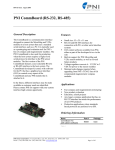
Mechanically mounting the TCM2.5/2.6
Refer to the TCM2.5/2.6 Dimensional Specification later in this manual for the TCM2.5/2.6 board
dimensions and the orientation of the reference frame.
The TCM2.5/2.6 is factory calibrated with respect to the mounting holes, as shown below, thus it
must be aligned within the host system with respect to these mounting holes, not the board edges.
Figure 1: TCM2.5 Mounting Diagram
Figure 2: TCM2.6 Mounting Diagram
PNI Sensor Corporation
TCM2.5 & TCM2.6 User Manual
DOC#1009269 r11
Page 11 of 49
Using the TCM2.5/2.6
RS232 Data Output Word
The TCM2.5/2.6 sends an “output word” in ASCII across the RS232 serial link when issued the s?
(Single Output Word) command, or when in go (Continuous Sampling) mode. This data output
word may be configured by the user for the desired format and configuration. You may select either
NMEA 0183, or TCM2 standard output word formats, with the sdo= (Set RS-232 Output Word)
command.
NMEA 0183 Format
The TCM2.5/2.6 can be configured to conform to the NMEA (National Maritime Electronics
Association) 0183 specification, which describes a standard RS232 bus format for exchange of a
variety of navigation information (GPS, radar, compass, and so on). In the NMEA output format,
only compass heading information is available. Inclinometer, magnetometer, thermometer data and
the distortion detection warning are all unavailable.
$HCHDM,<compass>,M*checksum<cr><lf>
!for magnetic heading
For example,
$HCHDM,182.3,M*checksum<cr><lf>
!for magnetic heading = 182.3 °
The checksum value is the result of XOR’ing the ASCII bytes between the ‘$’ and ‘*’ characters.
This one byte value is reported in the output word by two ASCII characters representing two hex
digits, with the most significant nibble first. For example, “...*A3<cr><lf>” indicates that the
output word has a decimal checksum value of 163.
PNI Sensor Corporation
TCM2.5 & TCM2.6 User Manual
DOC#1009269 r11
Page 12 of 49
TCM2.5/2.6 Standard Output
The TCM2.5/2.6 standard output format may be configured to provide all of the sensor data
parameters available, or only those parameters required.
$C<compass>P<pitch>R<roll>X<Bx>Y<By>Z<Bz>T<temp>E<error
code>*checksum<cr><lf>
View the sections covering the commands: c? (Compass Update), m? (Magnetometer Update), i?
(Inclinometer Update), t? (Temperature Update) for detailed information regarding the character
formatting and resolution of the values for each of the data parameters in the output word.
Example
The TCM2.5/2.6 will return the following:
$C328.3P28.4R-12.4X55.11Y12.33Z-18.43T22.3E001*checksum<cr><lf>
under the following conditions:
compass heading = 328.3 ° (true or magnetic, depending on configuration)
pitch = 28.4 °
roll = -12.4 °
Bx = 55.11µT (x-component of magnetic field)
By = 12.33 µT (y-component of magnetic field)
Bz = -18.43 µT (z-component of magnetic field)
Temperature = 22.3 ° (F/C depending on configuration)
E001 = Distortion flag is raised–magnetic anomaly nearby
Any parameters not enabled are not included in the output word.
For example:
$C328.3T22.3*checksum<cr><lf> !for compass and thermometer information only.
The checksum value is computed and reported identically to that for the NMEA output format.
PNI Sensor Corporation
TCM2.5 & TCM2.6 User Manual
DOC#1009269 r11
Page 13 of 49
Command Syntax
There are three types of commands you may issue to the TCM2.5/2.6:
User Configuration Parameter commands which set user-definable parameters.
Request for Data commands which query the TCM2.5/2.6 for data or for the stored value of
user-definable parameters.
Action commands which prompt the TCM2.5/2.6 to perform a specific action.
All commands must be followed with a <cr>, or <cr><lf>. The <lf> characters are ignored by the
TCM2.5/2.6, but are supported to allow compatibility with a variety of terminals.
Commands are case sensitive.
Programming Conventions
Set TCM2.5/2.6 user parameters:
<parameter>=<value><cr>
Query TCM2.5/2.6 data (parameter or sensor values):
<parameter>?<cr>
Action command:
<command><cr>
Detailed descriptions of all commands are in the “Command List” and a command summary is
shown in “Command List Quick Reference”
Data Transmission
The TCM2.5/2.6 will transmit data across the RS-232 interface in response to input commands, and
will also transmit data output words automatically when placed in continuous output mode. The
response to the various commands is as follows:
Input Command
TCM2.5/2.6 Response
Valid parameter-setting commands
:<cr><lf>
Valid action command
varies according to command
Valid Parameter query commands
:<parameter>=<value><cr><lf>
Invalid, or unrecognized command
:E<code><cr><lf>
Valid sensor query command
varies according to command
The ‘:’ character signifies a successfully identified and executed command.
Table 2: Input Command Responses
PNI Sensor Corporation
TCM2.5 & TCM2.6 User Manual
DOC#1009269 r11
Page 14 of 49
Error Codes
Error codes are given in the output word immediately before the checksum output indicated by the
letter “E” followed by three ASCII characters representing hexadecimal digits (for example, ASCII F
equals hexadecimal value F, or decimal value 15). Each error condition corresponds to one bit
within one of the hexadecimal digits. When the error condition exists, that bit will be set equal to 1 in
the error code transmitted by the TCM2.5/2.6. The error conditions and their corresponding bit
locations are listed below. Refer to Table 4: Common Error Codes for a list of the most common
error codes.
Table 3: Bit Locations of Error Conditions
st
1 ASCII Character
Bit 3 (MSB)
EEPROM1 error
Bit 2
EEPROM2 error
Bit 1
Reserved for future use (always 0)
Bit 0 (LSB)
Reserved for future use (always 0)
2
nd
ASCII Character
Bit 3 (MSB)
Reserved for future use (always 0)
Bit 2
Command parameter invalid
Bit 1
Reserved for future use (always 0)
Bit 0 (LSB)
Command invalid or not supported on
current TCM
rd
3 ASCII Character
Bit 3 (MSB)
Reserved for future use (always 0)
Bit 2
Magnetometer out of range
Bit 1
Inclinometer out of range
Bit 0 (LSB)
Reserved for future use (always 0)
Table 4: Common Error Codes
Error Code
Description
E002
Inclinometer out of range
E004
Magnetometer out of range
E006
Magnetometer out of range + Inclinometer out of range
E010
Command invalid or not available
E040
Command parameter invalid
E050
Command invalid or not available + Command parameter invalid
E400
EEPROM2 error
a
E800
EEPROM1 error
a
EC00
EEPROM2 error + EEPROM1 error
a
a. Indicates that the TCM2.5/2.6 EEPROM has been corrupted. Contact PNI for assistance.
PNI Sensor Corporation
TCM2.5 & TCM2.6 User Manual
DOC#1009269 r11
Page 15 of 49
Description of Error Conditions
Command Parameter Invalid – contains an invalid or out of range value.
Command invalid or not available on current model of TCM2 – is not recognized by the
TCM2.5/2.6. The syntax is incorrect, or you have entered a command which is not supported by
the TCM model you are using.
Inclinometer out of range – the inclinometer sensor is detecting an attitude that is outside of its
operational range of maximum pitch and roll. When this error flag is raised, compass and
inclinometer output data should be disregarded.
Magnetometer out of range – the magnetometer sensors are detecting an ambient magnetic
field that exceeds the maximum field measurement range of the magnetometer in any of the
three axes.
Compass Operating Modes
Standby Mode
The TCM2.5/2.6 is in Standby mode when you issue an h (Halt) command or ax (Warm Reboot).
You may configure and verify the TCM2.5/2.6’s user parameters in the Standby mode (set sampling
rate, filter parameters, and so on.) You may also query the TCM2.5/2.6 for single updates of
compass heading, pitch and roll, magnetic field strength, and temperature.
Sampling in Standby Mode
You can receive data from the TCM2.5/2.6 sensors from the h (Halt Continuous Sampling, Enter
Standby) mode. You may wish to do this if you are manually operating the TCM2.5/2.6 for
evaluation purposes, or if the TCM2.5/2.6 only needs to be polled periodically. With the TCM2.5/2.6
in the Standby mode, you can query sensor data by either issuing single parameter updates with
commands like c? (Compass Update), m? (Magnetometer Update) or you can receive output word
updates by issuing the s? (Single Update of Output Word) command. The output word may be
configured as previously described in “TCM2.5/2.6 Standard Output” to provide either NMEA
formatted compass data, or the TCM2.5/2.6 Standard output word, which presents any combination
of TCM2.5/2.6 sensor data that you wish to receive. The single parameter updates allow you to
immediately query any sensor data.
Continuous Sampling Mode
After configuring the TCM2.5/2.6 in the Standby mode, issue the go command to place the
TCM2.5/2.6 into Continuous Sampling mode. In this mode, the TCM2.5/2.6 samples its sensors,
processes, and outputs this sensor data at a rate determined by the SP parameter, default is 8 Hz.
PNI Sensor Corporation
TCM2.5 & TCM2.6 User Manual
DOC#1009269 r11
Page 16 of 49
User Calibration
All compasses can perform well in a controlled environment, where the ambient magnetic field
consists solely of the earth’s field. In most practical applications, however, an electronic compass
module will be mounted in a host system such as a vehicle that can contain large sources of local
magnetic fields: ferrous metal chassis, transformer cores, electrical currents, and permanent
magnets in electric motors.
By performing the user calibration procedure, you allow the TCM2.5/2.6 to identify the major
sources of these local magnetic anomalies and subsequently cancel out their effects when
measuring the earth’s magnetic field for computing compass headings. When you perform the user
calibration procedure, the TCM2.5/2.6 takes a series of magnetic field measurements. It analyzes
these total field measurements in order to identify the components that are created by the earth’s
field, which is the desired signal, from those components that are generated by the local
environment, which we wish to subtract out.
The end goal of the procedure for the TCM2.5/2.6 is to have an accurate measurement of the static
three-dimensional magnetic field vector generated by its host system at its mounting location. This
vector is subsequently subtracted out of run-time field measurement to yield the resultant earth’s
field vector.
One major benefit from the TCM2.5/2.6’s triaxial magnetometer/triaxial inclinometer system
configuration is its ability to compensate for distortion effects in all orientations throughout its usable
tilt range. As we have mentioned, a compass must measure the local field vector generated by the
host system at its current position within the system in order to accurately calibrate. Because the
TCM2.5/2.6’s magnetometer is strapped-down, or fixed with respect to its host system, this local
field vector does not change as the host system’s attitude changes, allowing the TCM2.5/2.6 to
accurately compensate in all pitch and roll orientations. Gimbaled fluxgates, for instance, are
unable to provide accurate calibration in non-level orientations because its magnetometers, being
gimbaled, change position with respect to the host system as attitude changes. This presents a
different local distortion field than that measured during calibration.
PNI Sensor Corporation
TCM2.5 & TCM2.6 User Manual
DOC#1009269 r11
Page 17 of 49
Multipoint Calibration (mpcal)
Key Points
Tilt as much as possible during the calibration. This allows the compass to take full
advantage of the 3-axis magnetometer.
Move slowly, take as much as 30 seconds to complete a circle. You are trying to get an
even sampling of the magnetic field over as many headings and tilts as possible.
Pay attention to the calibration score. Performance will be compromised if you accept a
low score.
If you get a poor calibration, clear it before making a new calibration.
Procedure
1. Clear any previous calibration by sending cc.
2. Enable multipoint calibration by sending mpcal=e.
3. Put the TCM2.5/2.6 into continuous mode by sending go.
4. Begin rotating the TCM2.5/2.6 in a circle while applying pitch and roll to the unit. The unit will
have the appearance of a “wobbling top” as it is moved through the calibration routine.
Turn the TCM2.5/2.6 around at least twice changing the pitch and roll as much as possible.
Each turn should take longer than 30 seconds. The turn does not need to be a perfect
circle.
In the calibration mode, the TCM2.5/2.6 is trying to take as many different data points as
possible to determine the magnetic anomalies.
The more pitch and roll points you give it, the better it is able to determine the vertical
magnetic fields.
Apply as close to a ± 90˚ pitch and ± 90˚ roll as possible. Doing so will improve the quality
of the calibration. Do not worry about exceeding the tilt range of the unit.
5. Halt the TCM2.5/2.6 by sending h if halt=e; or h <return> if halt=d.
6. Finish the calibration by sending mpcal=d.
7. Check the calibration score by sending lc?.
If the calibration score is not satisfactory, repeat the calibration process
PNI Sensor Corporation
TCM2.5 & TCM2.6 User Manual
DOC#1009269 r11
Page 18 of 49
Interpreting the Calibration Score
The TCM2.5/2.6 provides feedback on calibration through the calibration score, which has
the following format: “...HnVnMn.n....”
The first two numbers in the calibration score, HnVn, respectively describe the quality of the
calibration for the horizontal component and vertical component of the host system’s local
magnetic field. Higher numbers reflect higher quality. The highest possible score is a “9”.
The factors that contribute to a good score for Hn and Vn are as follows:
a good, magnetically quiet location was chosen for the user calibration procedure.
the magnetic environment is stable; there are no large sources of changing fields.
the calibration data points included changes in system heading and inclination to
allow for proper measurement of the horizontal and vertical field vectors.
there are no significant soft-iron distortion effects.
The last number in the score, Mn.n, describes the magnitude of local field. Larger numbers
denote strong local fields. Small local fields are preferable, since less correction will be
necessary, and they utilize less of the magnetometers’ dynamic range. A magnitude score
greater than 30 indicates strong magnetic fields at the TCM2.5/2.6 location; you should
consider alternative mounting locations. Any score less than 10 is very good.
Note: The calibration score values mostly provide a qualitative estimation. For example, a
good score would be H9V9Mn.n. A poor score as anything less than H9V9Mn.n. A poor V
score generally indicates that you need to tilt more during the calibration. A poor H score
indicates you did not turn two full circles or that you turned too quickly.
Soft Iron Effects
The TCM2.5/2.6 can calibrate for hard iron effects, or local fields that can be modeled as
static fields such as those created by permanent magnets. Hard iron distortions are
significant in most systems. There is another class of iron effects, soft iron, that are an
amplification of magnetic fields created by highly permeable materials, such as ferrous
metals. The TCM2.5/2.6 does not compensate for soft iron effects. Soft iron effects,
however, are generally far weaker than hard iron effects in most systems, and can be more
readily defeated by choosing a suitable location to mount your compass module.
In some systems, however, it may be difficult to avoid large masses of ferrous metal that
may create non-trivial soft iron effects, such as an armor plate in a tracked vehicle. In these
instances, try to locate the module as far away from the ferrous metals as possible. Soft
iron effects decrease with distance by an inverse square relation so even modest
separation can be effective.
Other Limitations
As discussed, the TCM2.5/2.6 models local disturbances as a static magnetic vector
contribution to the earth’s field. Any local fields, which are not static, will create errors. You
cannot calibrate for anomalies that are not fixed with respect to the compass. For example,
you may know that the TCM2.5/2.6 will be used in close proximity to other vehicles. You
cannot calibrate for the effects of these other vehicles, as they will be moving with respect
to the TCM2.5/2.6. This is a limitation universal to all compasses. Consider, therefore, the
TCM2.5/2.6’s position relative to any potential sources of field that will not be static:
magnetic cargo or payloads that may be placed in close proximity, fans or other electrical
equipment that may be turned on and off, and so on.
PNI Sensor Corporation
TCM2.5 & TCM2.6 User Manual
DOC#1009269 r11
Page 19 of 49
The TCM2.5/2.6 can calibrate for any environment that creates a magnetic field that
does not exceed the dynamic range of its magnetometers.
Declination Value
Declination, also called magnetic variation, is the difference between true and magnetic north,
relative to a point on the earth. It is measured in degrees east or west of true north. Correcting for
declination is accomplished by storing the correct declination angle, and then changing the heading
reference from magnetic north to true north. Declination angles vary throughout the world, and
change very slowly over time. For the greatest possible accuracy, go to the National Geophysical
Data Center web page below to get the declination angle based on your latitude and longitude:
http://www.ngdc.noaa.gov/cgi-bin/seg/gmag/fldsnth1.pl
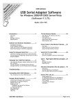
Pitch and Roll
The TCM2.5/2.6 uses accelerometers to measure the orientation of the compass with respect to
gravity. Since the compass also measures the complete magnetic field, the TCM2.5/2.6 can
correct for the tilt of the compass to provide an accurate heading.
The TCM2.5/2.6 utilizes Euler angles as the method for determining accurate orientation. This
method is the same used in aircraft orientation where the outputs are Heading (Yaw), Pitch and Roll.
When using Euler angles pitch and roll are defined as the angle rotated around an axis through the
center of the fuselage; pitch is rotation around an axis through the center of the wings. These two
rotations are independent of each other since the rotation axes rotate with the plane body.
For the TCM2.5/2.6 a positive pitch is when the front edge of the board is rotated upward and a
positive roll is when the right edge of the board is rotated downward.
Figure 3: TCM2.5 Pitch & Roll Axes
Figure 4: TCM2.6 Pitch & Roll Axes
PNI Sensor Corporation
TCM2.5 & TCM2.6 User Manual
DOC#1009269 r11
Page 20 of 49
Programming Commands
Table 5: Command List Quick Reference
Command
Description
Request for Data Commands
c?
Compass Update
i?
Inclinometer Update
lc?
Query Last Calibration Score
m?
Magnetometer Update
s?
Single Update Output Word
t?
Temperature Update
Action Commands
cc
Clear Calibration Data
factory
Factory Settings
go
Enter Continuous Mode
h
Halt Continuous Sampling, Enter Standby
halt=
Enable Single Character Halt
mpcal=
Multipoint Calibration
sleep
Sleep Mode (improved sleep mode over TCM2)
wake
Wake Mode (requires separate program and connection of RTS pin)
ax
Warm Reboot
User Configuration Parameter Commands
b=
Set Baud Rate
damping=
Enable Filter for damping of output
ec=
Enable Compass Data for Output Word
em=
Enable Magnetometer Data for Output Word
ep=
Enable Pitch Data for Output Word
er=
Enable Roll Data for Output Word
et=
Enable Temperature Data for Output Word
ma=
Select Magnetometer Output Option
mag_dec=
Set Declination Angle
sdo=
Set RS232 Output Word Format
sn=
Select Magnetic or True North
timeconst=
Set the value for filtering (damping) of outputs.
uc=
Set Compass Units
ui=
Set Inclinometer Units
ut=
Set Temperature Units
PNI Sensor Corporation
TCM2.5 & TCM2.6 User Manual
DOC#1009269 r11
Page 21 of 49
Command differences between the TCM2.5/2.6 and previous TCM2 units
To keep the software compatible with existing systems, when any of the commands below are sent
the unit will respond with the “:” as if it had accepted the command. Querying the command will
result in an error code, since the command is obsolete and not being used.
Command
Description
Commands not used for the TCM2.5/2.6
autocal
Autocalibration
%skip=
Skip measurements
cclip=
Set Clip Value
clock=
Set Clock rate
ed=
Enable Magnetic Distortion Alarm
fast=
Enable Fast Sampling
sao=
Select Analog Output Option
save
Unit automatically saves any changed settings
seriallp=
Lower Power Serial Consumption (specific to older chip)
Table 6: TCM2 vs TCM2.5/2.6 Commands
PNI Sensor Corporation
TCM2.5 & TCM2.6 User Manual
DOC#1009269 r11
Page 22 of 49
Request for Data Commands
Query Commands
c?
(Compass Update)
Description
Samples the magnetometer and inclinometer sensors, then calculates and returns
the compass heading. When in Standby mode (h) use this command to query the
compass reading regardless of whether compass data has been selected for
inclusion in the output word.
Syntax
c?<cr>
Output
when compass units are set to degrees:
$Cnnn.n[Ennn]*checksum<cr><lf>:<cr><lf>
when compass units are set to mils:
$Cnnn.n[Ennn]<cr><lf>:<cr><lf>
Resolution
0.1˚ or 2 mils
Valid Values
0 to 359.9˚ or, 0 to 6399 mils
Example
If TCM2 is configured for degrees:
c?<cr>
$C255.5[Ennn]*checksum<cr><lf>:<cr><lf>
If TCM2 is configured for mils:
c?<cr>
$C4480[Ennn]*checksum<cr><lf>:<cr><lf>
Related Commands
uc= (Set Compass Units)
ec= (Compass Data Enable)
PNI Sensor Corporation
TCM2.5 & TCM2.6 User Manual
DOC#1009269 r11
Page 23 of 49
i?
(Inclinometer Update)
Description Samples and returns the pitch and roll inclinometer data. When in Standby mode (h)
use this command to query the inclinometer readings regardless of whether
inclinometer data has been selected for inclusion in the output word.
Syntax
i?<cr>
Output
When the inclinometer units are set to degrees:
$P(-)nn.nR(-)nn.n[Ennn]*checksum<cr><lf>:<cr><lf>
When inclinometer units set to mils:
$P(-)nnnR(-)nnn[Ennn]*checksum<cr><lf>:<cr><lf>
Resolution
0.1° or 2 mils
Valid Values
0 to +80 ° or, 0 to +1421.6 mils
Example
i?<cr>
$P-30.0R-20.1[Ennn]*checksum<cr><lf>:<cr><lf>
Related Commands
ep= (Enable Pitch)
er= (Enable Roll)
PNI Sensor Corporation
TCM2.5 & TCM2.6 User Manual
DOC#1009269 r11
Page 24 of 49
lc?
(Query Last Calibration Score)
Description Reports the score generated by the last calibration procedure executed, as stored in
EEPROM. Use this command to recall the quality of the last calibration procedure.
Syntax
lc?<cr>
Output
HnVnMn.nn<cr><lf>
Valid Values
Example
0-9 for H and V
lc?<cr>
H7V8M8.00<cr><lf>
Related Commands
m?
!An example of a poor score
mpcal (Multipoint Calibration)
(Magnetometer Update)
Description Samples and returns the X, Y, and Z axes of magnetometer data. When in Standby
mode (h) use this command to query the magnetometer readings regardless of
whether magnetometer data has been selected for inclusion in the output word.
Syntax
m?<cr>
Output
$X(-)nn.nnY(-)nn.nnZ(-)nn.nn[Ennn]<cr><lf>:<cr><lf>
Resolution
0.01 µT
Valid Values
0 to ±79.9 µT
Example
m?<cr>
$X25.00Y10.50Z-03.00[Ennn]*checksum<cr><lf>:<cr><lf>
PNI Sensor Corporation
TCM2.5 & TCM2.6 User Manual
DOC#1009269 r11
Page 25 of 49
Related Commands
s?
em= (Enable Magnetometer)
(Single Update of Output Word)
Description Transmits the output word you specified. This command can only be used in the
Standby (h) mode. The Select RS232 Output Word Format (sdo=) command allows
you to select between NMEA or TCM2.5/2.6 Standard formats for the output word. If
TCM2.5/2.6 Standard output is selected, only those data parameters that are
enabled (with ec, ep, er, em, et) will be output.
Syntax
s?<cr>
Output
Refer to “RS232 Data Output Word” for a full description of the output word formats.
Example
s?<cr>
$C328.3P28.4R-12.4X55.1Y12.3Z-18.4T22.3[Ennn]*checksum<cr><lf>:<cr><lf>
Related Commands
sdo= (Select RS232 Output Word Format)
ec= (Enable Compass Data for Output Word)
ep= (Enable Pitch Data for Output Word)
er= (Enable Roll Data for Output Word)
em= (Enable Magnetometer for Output Word)
et= (Enable Temperature Data for Output Word)
t?
(Temperature Update)
Description
Sample and return the ambient temperature. When in the Standby mode (h) use
this command to query the temperature readings regardless of whether temperature
data has been selected for inclusion in the output word.
Syntax
t?<cr>
Output
When the units are set to Celsius:
$T(-)nnn.n[Ennn]*checksum<cr><lf>:<cr><lf>
When units set to Fahrenheit:
$T(-)nnn[Ennn]*checksum<cr><lf>:<cr><lf>
Resolution
0.5 °C or 1 °F
Valid Values
-40.0 to 85.0 °C or -40 to 185 °F
Example
t?<cr>
$T25.5[Ennn]*checksum<cr><lf>:<cr><lf>
PNI Sensor Corporation
TCM2.5 & TCM2.6 User Manual
DOC#1009269 r11
Page 26 of 49
Related Commands
et= (Enable Temperature)
ut= (Set Temperature Units)
Action Commands
?
(Help Command)
Description All TCM2.5/2.6 commands are displayed using the “?” command.
cc
(Clear Calibration Data)
Description Erases all calibration data. Any further magnetometer or compass output is not
corrected for any local fields. This command is only valid during Standby Mode (h).
Use this command before recalibrating the TCM2.5/2.6 for a new or changed local
magnetic environment.
Syntax
cc<cr>
Output
HnVnMn.nn<cr><lf>
Example
cc<cr>
H0V0M0.00<cr><lf>
Query Response
lc? (Last Calibration Score)
Related Commands
mpcal= (Multipoint Calibration)
c? (Compass Update)
PNI Sensor Corporation
TCM2.5 & TCM2.6 User Manual
DOC#1009269 r11
Page 27 of 49
factory
(Factory Settings)
Description Resets the TCM2.5/2.6 to the factory settings. The internal modes are set to the
following factory defaults
b=5
er=e
mpcal=d
cc
et=d
sdo=t
damping=d
timeconst=8
sn=m
ec=e
halt=d
sp=8
em=d
ma=u
uc=d
ep=e
mag_dec=0.0
ui=d
Syntax
factory<cr>
Output
H0V0m0.00<cr><lf>
Example
factory<cr>
go
ut=c
(Enter Continuous Sampling Mode)
Description Enters the Continuous Sampling Mode (go). The TCM2.5/2.6 immediately begins
outputting sensors data at rate specified by the SP parameter, default is 8 Hz. Data is
automatically transmitted according to the Output Word Format (sdo=) currently
specified. To exit the TCM2.5/2.6 and return to Standby mode, issue the Halt
Continuous Sampling (h) command.
Syntax
go<cr>
Output
Selected data output word.
Example
go<cr>
Related Commands
s? (Single Update of Output Word)
h (Halt Continuous Sampling)
PNI Sensor Corporation
TCM2.5 & TCM2.6 User Manual
DOC#1009269 r11
Page 28 of 49
h
(Halt Continuous Sampling, Enter Standby)
Description
Exits Continuous Sampling Mode (go) and enters Standby mode (h). If this
command is received while the TCM2.5/2.6 is transmitting an output word, the
remainder of the output word will be sent before the TCM2.5/2.6 changes modes.
Syntax
h<cr>
Output
:[Ennn]<cr><lf>
Related Commands
halt=
go (Enter Continuous Sampling Mode)
halt= (Enable Single Character Halt)
(Enable Single Character Halt)
Description The halt command during go mode has optionally been made a single character
command using the halt=e command.
Syntax
halt=d<cr>
Output
:[Ennn]<cr><lf>
Valid Values
Input
Description
e
Enable, h command for halting the ouput
d
h <cr> command for halting the output (default setting)
Table 7: Valid halt= Values
:halt=
Query Response
halt?
Related Commands
go (Enter Continuous Sampling Mode)
PNI Sensor Corporation
TCM2.5 & TCM2.6 User Manual
DOC#1009269 r11
Page 29 of 49
mpcal=
(Multipoint Calibration)
Description Initiates a multipoint calibration. This command is only valid when used in
conjunction with Enter Continuous Sampling Mode (go). The TCM2.5/2.6 samples its
sensors and adds the data point to the current set of calibration data.
mpcal=e<cr>
:<cr><lf>
Syntax
go<cr>
.......
...... take data in continuous mode
h<cr> (or h)
:<cr><lf>
mpcal=d<cr>
Valid Values
Input
Description
e
e, enable multipoint calibration
d
d, disable multipoint calibration (default setting)
Table 8: Valid mpcal= Values
Output
HnVnMn.nn<cr><lf>
The TCM2.5/2.6 only reports a calibration score after it has been put in Standby mode (h), and
multipoint calibration has been disabled (mpcal=d)
Example
mpcal=e<cr>
:<cr><lf>
go<cr>
........
.......
take data in continuos mode
h<cr>
:<cr><lf>
mpcal=d<cr>
H4V3M5.00:<cr><lf>
(This is an example of a poor score)
:mpcal=
Query Response
mpcal?
Related Commands
lc? (Query Last Calibration Score)
PNI Sensor Corporation
TCM2.5 & TCM2.6 User Manual
DOC#1009269 r11
Page 30 of 49
sleep
(Sleep Mode)
Description Enters the sleep mode of operation. This command turns off the internal clocks and
the RS-232 chip.
Syntax
sleep<cr>
Output
Example
Related Commands
wake (Wake Mode)
wake
(Wake Mode)
Note:
Only used with the TCM2.5
Description
Enters the wake mode of operation. To wake the TCM2.5, a falling edge on the int2
(interrupt 2) pin of the processor is required. This is achieved by connecting pin 6
of the TCM2.5 connector to the RTS pin (pin 4 on a DB25 and pin 7 on a DB9) of
the COM port.
A sample wake.c program example is provided at the end of this document. To
wake the TCM2.6, toggle RxD line
Syntax
wake<cr>
Output
Example
Related Commands
sleep (Sleep Mode)
PNI Sensor Corporation
TCM2.5 & TCM2.6 User Manual
DOC#1009269 r11
Page 31 of 49
User Configuration Parameter Commands
The following commands allow you to set and query the values of the TCM2.5/2.6’s user configuration parameters. These parameters specify how the TCM2.5/2.6 will operate, such as damping,
baud rate, and so on. The TCM2.5/2.6 stores all parameter values in EEPROM when specified, so
that after a reboot or power cycling, it will return to the last configuration set. Note that any parameter that specifies a numeric value must be specified with the appropriate units of the current setting.
b=
(Set Baud Rate)
Description
Sets the baud rate for the RS232 interface. Note: This is now an immediate
command and a reset is no longer required.
Syntax
b=n<cr>
Output
:<cr><lf>
Valid Values
Input
Baud Rate
1
300
2
1200
3
2400
4
4800
5
9600 (default setting)
6
19200
7
38400
8
115200
Table 9: Valid b= Values
Example
b=5<cr>
!set baud rate to 9600 baud
:<cr><lf>
Query Response
b?
PNI Sensor Corporation
TCM2.5 & TCM2.6 User Manual
:b=
DOC#1009269 r11
Page 32 of 49
damping=
(Set Digital Damping)
Description Enables or disables filtering of the output.
Syntax
damping=n<cr>
Output
:[Ennn]<cr><lf>
Valid Values
Input
Description
e
enable damping
d
disable damping (default setting)
Table 10: Valid damping= values
Example
damping=e<cr>
!enable damping
:<cr><lf>
Query Response
damping?
:damping=
Related Commands
timeconst=
(set time constant for digital damping)
ec=
(Enable Compass Data for Output Word)
Description Enables or disables compass data for inclusion in the TCM2.5/2.6 Standard Output
Word.
Syntax
ec=n<cr>
Output
:[Ennn]<cr><lf>
PNI Sensor Corporation
TCM2.5 & TCM2.6 User Manual
DOC#1009269 r11
Page 33 of 49
Valid Values
Input
Description
e
Compass data enabled. It will be included in the output word. (Default setting)
d
Compass data disabled. It will be excluded in the output word
Table 11: Valid ec= Values
Example
ec=e<cr>
!include compass data in output word
:<cr><lf>
Query Response
em=
ec?
:ec=
(Enable Magnetometer Data for Output Word)
Description Enables or disables magnetometer data for inclusion in the TCM2.5/2.6 Standard
Output Word
Syntax
em=n<cr>
Output
:[Ennn]<cr><lf>
Valid Values
Input
Description
e
Magnetometer data enabled. It will be included from the output word.
d
Magnetometer data disabled. It will be excluded in the output word. (Default setting)
Table 12: Valid em= Values
Example
em=e<cr>
!enable magnetometer data
:<cr><lf>
Query Response
em?
PNI Sensor Corporation
TCM2.5 & TCM2.6 User Manual
:em=
DOC#1009269 r11
Page 34 of 49
ep=
(Enable Pitch Data for Output Word)
Description
Enables or disables pitch data for inclusion in the TCM2.5/2.6 Standard Output Word.
Syntax
ep=n<cr>
Output
:[Ennn]<cr><lf>
Valid Values
Input
Description
e
Pitch data enabled. It will be included from the output word. (Default setting)
d
Pitch data disabled. It will be excluded in the output word
Table 13: Valid ep= Values
Example
ep=e<cr>
!include pitch data in output word
:<cr><lf>
Query Response
er=
ep?
:ep=
(Enable Roll Data for Output Word)
Description Enables or disables roll data for inclusion in the TCM2.5/2.6 Standard Output Word.
Syntax
er=n<cr>
Output
:[Ennn]<cr><lf>
PNI Sensor Corporation
TCM2.5 & TCM2.6 User Manual
DOC#1009269 r11
Page 35 of 49
Valid Values
Input
Description
e
Roll data enabled. It will be included from the output word. (Default setting)
d
Roll data disabled. It will be excluded in the output word
Table 14: Valid er= Values
er=e<cr>
Example
!include roll data in output word
:<cr><lf>
Query Response
et=
er?
:er=
(Enable Temperature Data for Output Word)
Description Enables or disables temperature data for inclusion in the TCM2.5/2.6 Standard
Output Word.
Syntax
et=n<cr>
Output
:[Ennn]<cr><lf>
Valid Values
Input
Description
e
Temperature data enabled. It will be included from the output word.
d
Temperature data disabled. It will be excluded in the output word. (Default setting)
Table 15: Valid et= Values
Example
et=e<cr>
!include temperature data in output word
:<cr><lf>
Query Response
et?
PNI Sensor Corporation
TCM2.5 & TCM2.6 User Manual
:et=
DOC#1009269 r11
Page 36 of 49
ma=
(Select Magnetometer Output Option)
Description Outputs either corrected or non corrected magnetometer readings. If corrected
readings are selected, the magnetometer readings output by the TCM2.5/2.6 reflect
corrections to ambient field as a result of user calibration. If not corrected, the
magnetometer readings output reflect total ambient field, including local fields. Note
that compass readings always are based upon corrected magnetometer readings.
Syntax
ma=n<cr>
Output
:[Ennn]<cr><lf>
Valid Values
Input
Description
c
Choose corrected magnetometer readings.
u
Choose non corrected magnetometer readings.
(Default setting)
Table 16: Valid ma= Values
Example
ma=c<cr>
!corrected magnetometer readings
:<cr><lf>
:ma=
Query Response
ma?
mag_dec=
(Set Declination Angle)
Description Sets the magnetic declination angle in degrees. Sets the declination offset for a
reading of True North. Based on the setting of the Compass Units (uc) command.
Positive declination is easterly declination and negative is westerly declination. This
is not applied until True North is set to true.
Syntax
mag_dec=nn.n<cr>
Output
:[Ennn]<cr><lf>
PNI Sensor Corporation
TCM2.5 & TCM2.6 User Manual
DOC#1009269 r11
Page 37 of 49
Valid Values
Input
Description
nn.n
Declination angle in degrees (default is set to 0.0)
Table 17: Valid mag_dec= Values
Example
mag_dec=17.2
!sets the declination angle to 17.2 degrees
:<cr><lf>
Query Response
sdo=
:mag_dec=
mag_dec?
(Set RS232 Output Word Format)
Description Sets the output word format to be used in response to the Single Update Output
Word (sdo?) command and in Continuous Output Mode (go).
Syntax
sdo=n<cr>
Output
:[Ennn]<cr><lf>
Valid Values
Input
Description
t
Standard TCM output string (default)
n
NMEA 0183 output string
Table 18: Valid sdo= Values
Example
sdo=t<cr>
!output word format to TCM standard
:<cr><lf>
Query Response
sdo?
PNI Sensor Corporation
TCM2.5 & TCM2.6 User Manual
:sdo=
DOC#1009269 r11
Page 38 of 49
sn=
(Select Magnetic or True North)
Description Selects either magnetic or true north. True North sets the heading reference to True
North or Magnetic North. If the value is set to true, then declination is applied to get
the True North heading.
Syntax
sn=n<cr>
Output
:[Ennn]<cr><lf>
Valid Values
Input
Description
t
True North
m
Magnetic North (default setting)
Table 19: Valid sn= Values
Example
sn=t<cr>
!the declination angle set with mag_dec is added to the
!computed heading
:<cr><lf>
:sn=
Query Response
sn?
Related Commands
mag_dec= (Set Declination Angle)
PNI Sensor Corporation
TCM2.5 & TCM2.6 User Manual
DOC#1009269 r11
Page 39 of 49
sp=
(Set Sampling Period)
Description This command is used to set the sampling rate at which the data will be output in Hz.
NOTE: The function of this command has changed from the TCM2 in which the sp
was the clock divisor to derive the output rate.
Syntax
sp=n<cr>
Output
: [Ennn] <cr><1f>
Valid Values
Input
Description
1
1 Hz output rate
2
2 Hz output rate
3
3 Hz output rate
4
4 Hz output rate
5
5 Hz output rate
6
6 Hz output rate
7
7 Hz output rate
8
8 Hz output rate (default)
Table 20: Valid sp= Values
Example
sp=4<cr>
!output rate 4 Hz
:<cr><lf>
Query Response
sp?
PNI Sensor Corporation
TCM2.5 & TCM2.6 User Manual
:sp=
DOC#1009269 r11
Page 40 of 49
timeconst=
(Set Time Constant for Digital Damping)
Description This command is used with the digital damping command. It sets the time constant to
nn samples for the digital damping.
Syntax
timeconst=n<cr>
Output
:[Ennn]<cr><lf>
Valid Values
Input
Description
Integer value between 1 – 4
Set the measured time constant = 4
Integer value between 5 – 8
Set the measured time constant = 8 (default setting)
Integer value between 9 – 16
Set the measured time constant = 16
Integer value between 16 – 32
Set the measured time constant = 32
Table 21: Valid timeconst= Values
Example
timeconst=16<cr>
!Filter over 16 measurements
:<cr><lf>
:timeconst=
Query Response
timeconst?
Related Commands
damping= (Set Digital Damping)
PNI Sensor Corporation
TCM2.5 & TCM2.6 User Manual
DOC#1009269 r11
Page 41 of 49
uc=
(Set Compass Units)
Description
Sets the units to be used for the input and output of the heading data.
Syntax
uc=n<cr>
Output
:[Ennn]<cr><lf>
Valid Values
Input
Description
d
degrees, 360 × in a full circle (Default setting)
m
mils, 6400 mils in a full circle
Table 22: Valid uc= Values
uc=d<cr>
Example
!set units to degrees
:<cr><lf>
:uc=
Query Response
uc?
ui=
(Set Inclinometer Units)
Description
Sets the units to be used for the input and output of the tilt (pitch & roll) data.
Syntax
ui=n<cr>
Output
:[Ennn]<cr><lf>
Valid Values
Input
Description
d
degrees, 360 × in a full circle (Default setting)
m
mils, 6400 mils in a full circle
Table 23: Valid ui= Values
Example
ui=d<cr>
!set units to degrees
:<cr><lf>
Query Response
ui?
PNI Sensor Corporation
TCM2.5 & TCM2.6 User Manual
:ui=
DOC#1009269 r11
Page 42 of 49
ut=
(Set Temperature Units)
Description
Sets the units to be used for the input and output of the temperature data.
Syntax
ut=n<cr>
Output
:[Ennn]<cr><lf>
Valid Values
Input
Description
f
Fahrenheit
c
Celsius (Default setting)
Table 24: Valid ut= Values
Example
ut=f<cr>
!set units to Fahrenheit
:<cr><lf>
Query Response
ut?
PNI Sensor Corporation
TCM2.5 & TCM2.6 User Manual
:ut=
DOC#1009269 r11
Page 43 of 49
TCM2.5/2.6 Code Example
Wake C program
/*
in
/*
/*
wake.c - Sample program to wake the TCM2.5/2.6 after is has been put
sleep mode */
Wake toggles the RTS line to give the TCM2.5/2.6 a (falling) edge */
P Milford 1/10/96 */
/* Usage: wake 1 - wakes a tcm2.5/2.6 on com port 1 (default) */
/* wake 2 - wakes a tcm2.5/2.6 on com port 2, etc. */
#include <stdio.h>
#include <stdlib.h> /* for atoi */
#include <conio.h> /* For inp/out */
/* Addresses in IO space of the serial port base addresses */
#define
#define
#define
#define
PORT1
PORT2
PORT3
PORT4
0x3F8
0x2F8
0x3E8
0x2E8
#define MCR 4
#define RTS 2
/* Offset to the Modem control register */
/* RTS is bit 2 of the MCR*/
int main(int argc, char *argv[])
{
int tmp, port=PORT1;
/* Defaul to serial port 1 */
/* If there are args, look at the first one only */
if(argc == 2) {
/* Figure out which serial port to use */
switch(atoi(argv[1])) {
case 1: port = PORT1; break;
case 2: port = PORT2; break;
case 3: port = PORT3; break;
case 4: port = PORT4; break;
others: port = PORT1;
};
};
tmp = inp(port+MCR);
/* Read current line status */
outp(port+MCR, tmp ^ RTS); /* Toggle the RTS line */
outp(port+MCR, tmp);
/* Restore the RTS line */
return 0;
};
PNI Sensor Corporation
TCM2.5 & TCM2.6 User Manual
DOC#1009269 r11
Page 44 of 49
Performance Specifications
Parameter
Heading Specifications
Accuracy over tilt range
Resolution
Repeatability [1]
Max Dip Angle
Magnetometer Specifications
Calibrated Field Measurement
Range
Magnetic Resolution
Magnetic Repeatability
Tilt Specifications
Pitch Accuracy
Roll Accuracy
Tilt Range
Tilt Resolution
Tilt Repeatability [1]
Calibration
Hard Iron Calibration
Soft Iron Calibration
Mechanical Specifications
Dimensions (L x W x H)
Weight
Mounting Options
Connector for RS-232
I/O Specifications
Time to Good Initial Data from
Power-On
Time to Good Initial Data from
Sleep Mode
Maximum Sample Rate
RS-232 Communication Rate
Output Formats
Power Specifications
Supply Voltage
Current Draw at
maximum sample rate
Sleep Mode
Environmental Specifications
Operating Temperature
Storage Temperature
Typical
Units
0.8°
0.1°
0.1°
85°
Deg RMS
Deg
± 80
µT
± 0.05
± .1
0.2°
0.2°
± 50°
0.1°
0.1°
Deg RMS
Deg
Deg RMS
Yes
No
TCM2.5
TCM2.6
6.4 x 5.1 x 1.4
3.4 x 4.3 x 1.3
14
7
Screw Mounts/Standoffs horizontal
10-pin
9-pin
cm
grams
210
msec
80
msec
8
300 to 115200
TCM2 ASCII Protocol
TCM2.5
TCM2.6
5 V (regulated)
3.8 to 5.0 V
6 to 18 (unregulated)
(unregulated)
20 typical
20 typical
0.6 typical
0.6 typical
– 20 to 70
– 40 to 85
samples/sec
baud
VDC
mA
°C
[1] Repeatability is based on statistical data at ±3 sigma limt about the mean
Table 25: TCM2.5/2.6 Specifications
PNI Sensor Corporation
TCM2.5 & TCM2.6 User Manual
DOC#1009269 r11
Page 45 of 49
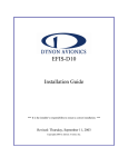
Mechanicals
TCM2.5 Board and Cable
The default orientation for the TCM2.5/2.6 is for the silk-screened arrow to point in the “forward”
direction. That puts the edge opposite of the Molex connector as the front edge of the board.
Figure 5: TCM2.5 Board Drawing
PNI Sensor Corporation
TCM2.5 & TCM2.6 User Manual
DOC#1009269 r11
Page 46 of 49
3 ft. Cable Assembly
Figure 6: 3’ Cable Drawing
PIN
Wire Color
Description
1
Orange
Vsupply (5 V regulated)
2
Red
Vsupply (6 to 18 V unregulated)
3
Black
Power Ground
4
Blue
RxD (RS-232) -5 to 5V
5
Yellow
TxD (RS-232) -5 to 5V or -12 to 12V
6
White
RTS, Wake from Sleep
7
Green
Data Ground
8
Brown
NC
9
Purple
NC
10
Gray
Data Ground
Table 26: Molex Connector TCM2.5 Pin Descriptions
PNI Sensor Corporation
TCM2.5 & TCM2.6 User Manual
DOC#1009269 r11
Page 47 of 49
TCM2.6 Board and Cable
The default orientation for the TCM2.6 is for the silk-screened arrow to point in the “forward”
direction. That puts the edge opposite of the Molex connector as the front edge of the board.
Figure 7: TCM2.6 Board Drawing
PNI Sensor Corporation
TCM2.5 & TCM2.6 User Manual
DOC#1009269 r11
Page 48 of 49
18 in. Cable Assembly
Figure 8: 18" Cable Drawing
PIN
Wire Color
Description
1
Black
Power Ground
2
Gray
NC
3
Green
RS232 Ground
4
Orange
NC
5
Violet
NC
6
Brown
NC
7
Yellow
TxD
8
Blue
RxD
9
Red
5 VDC
Table 27: Molex Connector TCM2.6 Pin Description
PNI Sensor Corporation
TCM2.5 & TCM2.6 User Manual
DOC#1009269 r11
Page 49 of 49