1
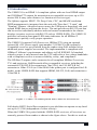
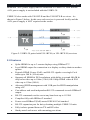
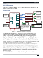
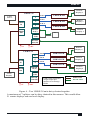
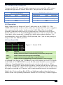
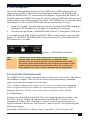
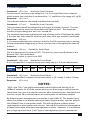
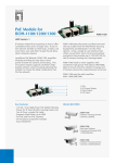
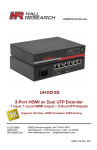
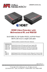
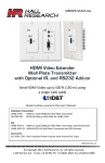
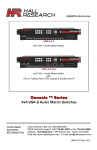
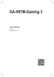
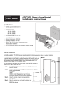
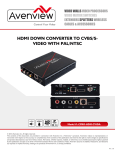
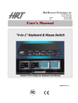
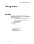
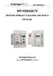
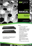
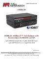
User’s Manual UHBX-3S HDMI On HDBaseT™ 1x3 Splitter with Local Loop-out, RS232, & PoH Split HDMI & Extend Video, Audio, RS232 & Power upto 500 ft (150 m) on a single Cat6 cable UMA1220 Rev B © Copyright 2014. Hall Research, Inc. All rights reserved. 1163 Warner Ave Tustin, CA 92780, Ph: (714)641-6607, Fax (714)641-6698 UHBX-3S Table of Contents 1.0 Introduction 3 2.0 Features 4 3.0 Setup 5 3.1 Package Contents 5 3.2 Installation 5 4.0 Operation 7 4.1 Front Panel LEDs 7 4.2 EDID Management 8 5.0 Serial (RS-232) Commands 8 5.1 Serial Setup 8 5.2 Serial Commands 9 6.0 Troubleshooting 10 7.0 Specifications 11 TRADEMARKS USED IN THIS MANUAL Hall Research and its logo are trademarks of Hall Research. Any other trademarks mentioned in this manual are acknowledged as the property of the trademark owners. FCC RADIO FREQUENCY INTERFERENCE STATEMENT This equipment generates, uses, and can radiate radio frequency energy and if not installed and used properly, that is, in strict accordance with the manufacturer’s instructions, may cause interference to radio communication. It has been designed to comply with the limits for a Class A computing device in accordance with the specifications in Subpart B of Part 15 of FCC rules, which are intended to provide reasonable protection against such interference when the equipment is operated in a commercial environment. Operation of this equipment in a residential area is likely to cause interference, in which case the user at their own expense will be required to take whatever measures may be necessary to correct the interference. Changes or modifications not expressly approved by the party responsible for compliance could void the user’s authority to operate the equipment. 2 UHBX-3S 1.0 Introduction The UHBX-3S is an HDMI 1.4 compliant splitter with one local HDMI output and 3 HDBaseT™ outputs for transmission to compatible receivers up to 150 meters/500 ft away (max distance is a function of receiver type). The Splitter supports HDCP, 3D, Deep Color, CEC, and 4Kx2K resolution. EDID management is integrated into the unit with "Pass-thru", "Learn", and "Emulate" features. Advanced users can use the USB port to download, edit, and upload EDID data to and from the device. The unit provides an RS-232 port that can be used to individually address and send control commands to the remote displays (requires receivers with RS-232 such as UHBX-R-PD). The UHBX-3S provides convenient front panel LED status indicators for all HDBaseT parameters to quickly verify proper operation. The UHBX-3S supports PoH (Power over HDBaseT™) using an optional external 48 v DC power supply (part number 511-PS4812 sold separately). Compatible receivers are powered from the sender using PoH standard so no additional power supplies are needed. The implementation is compliant with HDBaseT Alliance's requirements and adheres to PoE IEEE802.3af standard whereby power is only inserted onto the UTP cable after a low voltage handshake with a compliant receiver to assure reliability, safety, and compliance. The HD BaseT outputs can be connected to all compliant HDBaseT receivers, TV's and projectors. Hall Research offers ccompatible receivers including the economical UH-1BT-R for extension to 70m/230 ft, the UH-1BTX-R for extension to 100m /230 ft (or 150m/500ft if the splitter port is configured for LR mode), or the UHBX-R-PD that supports HDMI, RS-232, PoH, and extension to 150m/500 ft. Figure 1- UHBX-3S Sender paired with UHBX-R-PD receivers Full-duplex RS232 Serial Port extension is provided that can operate at any baud rate up to 115,200 (independent of video activity). When the UHBX-3S is paired with the UHBX-R-PD receivers, all receivers are remotely powered from sender as shown in the figure above. For this to work an 3 UHBX-3S additional +48V power supply must be connected to UHBX-3S. Note that the +48V power supply is not included with the UHBX-3S. UHBX-3S also works with UH-1BT-R and the UH-1BTX-R receivers. As shown in Figure 2 below. In this case each receiver is powered locally and the +48V power supply is NOT required at the sender. Figure 2- UHBX-3S paired with UH-1BT-R (or UH-1BTX-R) receivers 2.0 Features • Splits HDMI for up to 3 remote displays using HDBaseT™ • Local HDMI output for connection to a display or daisy-chain to another splitter • Extends HDMI, Power (PoH), and RS-232 signals over single Cat 6 cable up to 500 ft (150 m) max. • Supports all HDMI & DVI resolutions with ability to extend 4Kx2K & deep color video up to 100m (330 ft) OR 1080p HDMI video & DVI video up to 150m (500 ft). • Advanced EDID management with USB port for EDID manipulation using a PC • Can address and send independent RS-232 commands to each HDBaseT output. • RS-232 commands can be sent at any baud rate up to 115200 • Complies fully with HDBaseT standard • Power-over-HDBaseT(PoH) meets IEEE 802.3af standard • RS-232 expansion port for daisy-chaining multiple UHBX-3S units • Fully isolates ground between TX and RX sides • Sturdy metal enclosures with mounting provisions 4 UHBX-3S 3.0 Setup 3.1 Package Contents All UHBX-3S units are shipped with +5V power supply, a 1m HDMI cable and a male-to-female RS-232 cable. 3.2 Installation Remote Display 1 UHBX-3S Video Source 3 2 HDMI In 1 Cat 6 Mini USB Local Display RS-232 Out (M) UHBX-R-PD UHBX-R-PD Cat 6 Remote Display 2 UHBX-R-PD RS-232 In (F) HDMI Out +5V Cat 6 PC USB USB is only required to assign Output port numbers & to manage EDID. Remote Display 3 HDMI Cable RS-232 Cable +48V Figure 3 – UHBX-3S Application Diagram As shown in the diagram above, UHBX-3S is used to extend a single video source to three (3) remote displays, located within 500 ft (150 m) from the source. It also provides an additional HDMI output for connection to a local display or for daisy chaining to another UHBX-3S for more HDBaseT outputs. When the UHBX-3S is used with UHBX-R-PD receivers, the RS-232 and Power (PoH) signals are also extended on the same Cat 6 cable. The RS-232 In port is used to send/receive commands or data to/from remote displays connected at the output. Special RS-232 commands are provided to selectively communicate with any individual output (Please refer to Section 5 for more details.). Note: By default the output port numbers are assigned address 1 through 3. If RS-232 ports are daisy chained among several UHBX-3S devices then the user must assign different port numbers to each box so each HDBaseT output has a unique address. In order to do this the user must connect each additional box to a PC using the supplied using a USB cable (cable is type A to mini-USB) and utilize the "UHBX-3S Manager Software" available for download from Hall Research website. Multiple UHBX-3S boxes can be daily-chained together as shown below. 5 UHBX-3S Remote Display 1 UHBX-3S Video Source 3 2 HDMI In HDMI Out 1 Cat 6 Cat 6 UHBX-R-PD Cat 6 Remote Display 2 UHBX-R-PD RS-232 In (F) Mini USB UHBX-R-PD PC Remote Display 3 USB RS-232 Out (M) +5V +48V Remote Display 6 UHBX-3S 6 5 HDMI In HDMI Out Local Display 4 Cat 6 UHBX-R-PD UHBX-R-PD Cat 6 UHBX-R-PD RS-232 In (F) Remote Display 5 Remote Display 4 Mini USB RS-232 Out (M) +5V Cat 6 +48V USB is only required to assign Output port numbers & to manage EDID. HDMI Cable RS-232 Cable Figure 4 – Two UHBX-3S units daisy-chained together A maximum of 7 splitters can be daisy chained in this manner. This would allow 21 remote displays and one local display. 6 UHBX-3S 3.2.1 Sender Serial Connections Connect the RS-232 input (Female) connector to your controller or PC using a straight-through male-to-female DB9 cable. The pin-outs are shown below: RS-232 In (Female) DB9-F Pin Term Direction 2 TX Output 3 RX Input 5 GND RS-232 Out (Male) DB9-M Pin Term Direction 2 RX Input 3 TX Output 5 GND 4.0 Operation Make connections as shown in Figure 3 and power up the UHBX-3S. If the UHBX-R-PD is used as the receiver, make sure the optional 48V power supply is also connected to the sender. In this case the PoH LED will be lit in about 3 seconds to indicate that the receiver is getting power. When the Link LED on Sender and Receiver are lit (or blinking) the system is ready to extend video and if you have video connected, it should be visible on the remote displays. It is recommended to leave the EDID in PASS position, but if you are not getting an image switch it to EMUL position. 4.1 Front Panel LEDs Figure 5 – Sender LEDs Link Video LNG RCH PoH UTP Link. Solid on means Sender & Receiver are communicating Blinking means the ends are communicating in Low-Power (sleep) mode Solid on means Video is being sent to the display Solid on means the link is operating in Long Reach mode Solid On means PoH handshake successful and power is sent to receiver As shipped from factory, the 3 HDBaseT ports of the splitter are in AUTO mode, in this mode if a UHBX-R-PSE is used, the link mode should be set to standard (100m) or Long Reach (150m) using the mode switch on the receiver. When connected to UH-1BTX-R which does not have a mode switch, the user can force any of the 3 HDBaseT outputs of the Splitter into Long Reach mode. In this mode the signal can extend to 150 meters, and is more immune to noise or interference. If the Link, Video, and Lng Rch LED’s are blinking together, there has been a failure on the corresponding transmitter module or it is missing. Contact Support. 7 UHBX-3S 4.2 EDID Management One of the distinguishing features of the UHBX-3S is EDID management. It supports two modes of operation Pass-Through & Emulate. In Pass-through mode the EDID of the TV connected to the output(s) is passed to the source. In Emulate mode the UHBX-3S allows the user to send an EDID table that is stored in the splitter itself (independent of the sinks). The EDID mode is selectable from the front panel. The internal EDID table can be modified in two ways. 1. It can be "learned" from the display connected to the local HDMI output (by holding the SEL button for 5 seconds, or using the GUI software 2. The user can upload any valid EDID table from a PC through the USB port To switch between EMULATE and PASS-THRU modes, simply press the SEL button. To "LEARN" the EDID from locally connected TV press and hold the SEL button for 3 seconds. Figure 6 – EDID Mode Selection PASS EMUL Solid On means current EDID configuration is in Pass-Thru mode Solid On means current EDID configuration is in EMULATE mode Blinking means the selected mode is Pass-Thru (PASS LED will be solidly lit), but the splitter could not find any sinks at any of its 4 outputs so it has decided to emulate EDID from internal table. In this case as soon as you plug a display to any of the 4 outputs, the EMUL LED will stop blinking 5.0 Serial (RS-232) Commands The UHBX-3S has special commands that can be used to selectively send data to the HDBaseT outputs. This section describes serial port settings, command syntax and expected response from the unit. Note - If daisy-chaining more than one box, prior to using serial commands please assign a unique port number to each output port using the UHBX-3S Manager Software. Please refer to the software guide for more details. 5.1 Serial Setup Connect one end of M/F serial (RS-232) cable shipped with the product to the RS-232 In port of UHBX-3S and the other end to the RS-232 port of your computer (or USB to RS-232 adapter). Open a serial terminal program (e.g. HyperTerminal or Realterm, TeraTerm etc.) and set up the serial port using the following settings. Baud Rate: 19200, Bits: 8, Parity: None, Stop Bits: 1, Flow Control: Off 8 UHBX-3S 5.2 Serial Commands Command: XC,n <cr> stands for Serial Connect Connect serial interface to an output (n). If n is not specified, then it reports which output the controller is connected to. “n” could be in the range of 1 to 99 Response: XC,n <cr> This indicates that the command completed successfully Command: XT <cr> Stands for Serial Transmit This command should be followed by a string of characters to send. The user has 1-5 seconds to enter any characters from 0x00 to 0xFF. The maximum number of bytes being sent out can’t exceed 64. The terminal characters indicating the end of string are 0x17 followed by 0x0D. If the user has more than 64 bytes to send, they must use multiple commands. Response: OK <cr> It is recommended that the customer wait for the OK response prior to issuing further commands. Neglecting to do so runs the risk of corrupting the internal buffers. Command: XR <cr> Stands for Serial Read Get the contents of the receive FIFO. The unit can store upto 64 bytes in the Receive FIFO. This commands Response: x bytes or none in the FIFO Command: XB,n <cr> Stands for Serial Baud If n is not specified, it reports the current baud rate (n = 1-8 per table below) N Baud Rate Response: 1 2 3 4 5 6 7 8 1200 2400 4800 9600 19200 38400 57600 115200 XBn <cr> Command: XP,n <cr> Stands for Serial Parity If n is not specified, it reports the current parity. n: (0 = None, 1=Odd, 2=Even) Response: XP,n <cr> NOTES: “XB,n” and “XP,n” are global commands and will affect the setting for all HDBaseT outputs. So if all the remote devices you are trying to control use the same baud rate, you only need to issue the XB,n command once. Otherwise you need to use the XB,n command prior to sending data to individual outputs By Default power management is turned on in the UHBX-3S. This means that if there is no video or no display connected (Hot Plug not active), the unit will put the HDBaseT links in low power mode. This will significantly reduce power consumption in both splitter and receiver. You can still send Serial commands at all baud rates when the power management is active . However, it is possible to get a single spurious extra “junk” byte at the beginning of your command as 9 UHBX-3S received at the remote site if the command was issued with the HDBaseT link in low-power mode. This byte is typically hex FF or FE and will only occur at baud rates above 38400. If the device you are trying to control is going to get confused by the hex FF or FE at the beginning of a command string, you can do one of two things: (a) Anticipate it and make changes to your command string to handle it. For example you can issue a Carriage return first followed by your actual command, or send your command twice. (b) Disable the power management in the UHBX-3S using the GUI 6.0 Troubleshooting If you are experiencing problems getting the extender to work properly, please use the following troubleshooting suggestions. Make sure that all of the connections on both the sender and the receiver are solid. Loose connections are the number one cause of issues. Try resetting the system by cycling power on the Splitter. Check the state of the LED’s on the front of both the sender and the receiver. If the Link, Video, and Lng Rch LED’s are blinking together, there has been a failure on the corresponding transmitter module or it is missing. Change the EDID mode using the front panel push button. Make sure the Cat6 cables are not run next to power cables or ballasts. Even if the length of the cable is less than 100 meters, if the screen is blanking or shows glitches, place the HDBaseT link in Long Reach mode. In this mode the signal is much stronger, can go farther and offers extra immunity to interference and electrostatic discharge (ESD). To do this, when using UHBXR-PD as receiver, put the link in Long Reach mode using the small slide switch. If you are using UH-1BTX-R that does not have a LR switch, you can force the link in LR mode from the UHBX-3S using the Windows GUI software through the USB port. The unit will remember the last setting. Update the firmware in the splitter (contact Hall Research Support) Make sure that the UTP or STP cable meets the requirements. Never use lowskew cable for digital video extension (low skew cables are suited for analog video extension, but do not work well for digital video). If you still are unable to get the system working, contact Hall Research support with a detailed description of the issue and the steps you have taken. Do not open or try to repair the unit yourself as this will void your warranty. To return the extender for repair, you must contact HR Support at 714-641-6607 or via email or web. To ship the unit back for repair, make sure to obtain a Return Material Authorization (RMA) number. 10 UHBX-3S 7.0 Specifications Input & Output ports Input Port 1x HDMI Female (Type A) Output Port 1x HDMI Female (Type A), 3x RJ45 connectors Video Standards Signal type Connectors Resolutions Audio Formats Other Signals DDC CEC RS232 PoH DVI (single link) and HDMI (compliant with 12 bit color depth, 3D video) HDBaseT Locking HDMI DVI signal VGA (640x480) thru WUXGA (1920x1200) HDTV signal 480i through 1080p Digital Cinema 4K (4096x2160) – Not supported in Long Reach All HDMI Embedded Audio including: LPCM 7.1CH, Dolby TrueHD and DTS-HD Master Audio (32-192kHz sample rate) Pass-Thru DDC for reading EDID directly from remotely connected LCD and HDCP handshake Pass-Thru CEC for Consumer Electronics Control compatible devices Bidirectional (full-duplex) any baud rate up to 115,200 Power-over-HDBaseT meets IEEE 802.3af standard. PD side identifies as Class 2 (3.84–6.49 watts). Actual power consumption of PD side is 5.5 watts max General Power Supply 100 VAC to 240 VAC, 50-60 Hz, external; 5 VDC, 3.2 A Actual DC current 1.6A max PoH Supply (Optional ) 100 VAC to 240 VAC, 50-60 Hz, external; 48VDC Power 10.15 watts maximum Temp/humidity Storage: -40 to +158 °F (-40 to +70 °C) 10~ 90%, non-condensing Operating: +32 to +122 °F (0 to +50 °C) 10~ 90%, non-condensing Cooling Convection Mounting Threaded nuts on bottom for rack-shelf mounting or optional rack ears Enclosure type Metal (Aluminum ends, Aluminum Extrusion) Dimensions 1.66" H x 8.42" W x 5.59" D (42mm H x 214mm W x 141mm D) Product weight Vibration Safety EMI/EMC MTBF Product – 2.5 lbs (0.386kg) Shipping – 3 lbs (0.681 kg) ISTA 1A in carton (International Safe Transit Association) CE CE, FCC Class A 90,000 hours (estimate) Specifications are subject to change without notice 11 UHBX-3S © Copyright 2014. Hall Research, Inc. All rights reserved. 1163 Warner Ave., Tustin, CA 92780 Ph: (714)641-6607 12