1
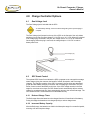
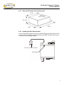
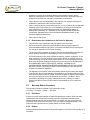
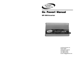
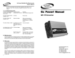
Go Power!™ Manual GPC - Converter / Charger GPC-15 GPC-30 GPC-45 GPC-55 GPC-75 Go Power! Converter / Charger Owner’s Manual Contents 1.0 1.1 1.2 2.0 2.1 2.2 3.0 3.1 3.2 3.3 3.4 4.0 Important Safety Instructions ...................................................................4 General Safety Precautions ................................................................................. 4 Precautions When Working with Batteries ........................................................... 4 Features ......................................................................................................5 Protection Features .............................................................................................. 5 Electrical Specifications........................................................................................ 5 Installation Guidelines...............................................................................6 Installation ............................................................................................................ 6 Mounting Location ................................................................................................ 6 120 Volt AC Input ................................................................................................. 6 Reverse Polarity Fuses ........................................................................................ 6 Charge Controller Options........................................................................7 4.1 Dual Voltage Jack................................................................................................. 7 4.2 GPC Smart Control............................................................................................... 7 4.2.1 Reduced Charge Times ................................................................................ 7 4.2.2 Increased Battery Capacity ........................................................................... 7 4.2.3 Reduced Battery Stress ................................................................................ 8 4.2.4 Weekly Equalization for Longer Battery Life ................................................. 8 4.2.5 LED Indicator................................................................................................. 8 4.2.6 Charging Voltages......................................................................................... 8 4.2.7 External GPC Smart Control Dimensions ..................................................... 9 4.2.8 Installing the GPC Smart Control .................................................................. 9 5.0 Warranty ...................................................................................................10 5.1 Go Power! 2 Year Limited Warranty................................................................... 10 5.1.1 What the Go Power! Warranty Covers and for How Long .......................... 10 5.1.2 What the Go Power! Warranty Does Not Cover ......................................... 10 5.1.3 Restrictions and Limitations to Go Power!’s Warranty................................ 11 5.2 Warranty Return Procedure ............................................................................... 11 5.2.1 End Users.................................................................................................... 11 5.2.2 Dealers ........................................................................................................ 11 5.2.3 Units bought directly from Go Power! ......................................................... 12 5.3 Additional Information......................................................................................... 12 5.4 Out of Warranty Items ........................................................................................ 12 3 Go Power! Converter / Charger Owner’s Manual 1.0 Important Safety Instructions Before you install and use your Go Power! Converter / Charger, be sure to read these safety instructions. To get the most out of your GP Converter / Charger, it must be installed and used properly. Please read the instructions in this manual before installing and using your battery charger. 1.1 General Safety Precautions 1. Do not expose the GP Converter / Charger to rain, snow, spray, bilge, or dust. To reduce risk of hazard do not cover or obstruct the ventilation openings. 2. Do not install the GP Converter / Charger in a zero-clearance compartment. Overheating may result. 3. To avoid a risk of fire and electronic shock, ensure that existing wiring is in good electrical condition; and that wire size is not undersized. Do not operate the GP Converter / Charger with damaged or substandard wiring. 4. The battery terminal not connected to the chassis has to be connected first. The other connection is to be made to the chassis, remote from the battery and fuel line. The battery converter / charger is then to be connected to the supply mains. 5. After charging, disconnect the GP Converter / Charger from supply mains. Then remove the chassis connection and battery connection, in this order. 6. Do not charge non-rechargeable batteries. 7. During charging the battery must be placed in a well-ventilated area. 8. The battery converter / charger must only be plugged-in to a grounded outlet. 9. If the power supply cord is damaged, the manufacturer or its service agent or a similar qualified person must replace it in order to avoid a hazard. 1.2 Precautions When Working with Batteries 1. If battery acid contacts skin or clothing, wash immediately with soap and water. If acid enters eye, immediately flood eye with running cold water for at least 20 minutes and get medical attention immediately. 2. Never smoke or allow a spark or flame in vicinity of battery or engine. 3. Do not drop a metal tool on the battery. The resulting spark or short-circuit on the battery or other electrical part may cause an explosion. 4. Remove personal metal items such as rings, bracelets, necklaces, and watches when working with a lead-acid battery. A lead-acid battery produces a short-circuit current high enough to weld a ring, or the like, to metal, causing a severe burn. 4 Go Power! Converter / Charger Owner’s Manual 2.0 Features The Go Power! Converter / Charger (GPC) series power converter / battery charger converts 120 V nominal AC to 13.6 V DC. As a power supply, its tightly controlled regulation allows the user to operate any 12 V nominal DC load up to the converter’s rated output current. As a battery charger, the converter will maintain the battery, delivering its full-rated current when the battery capacity falls sufficiently low. The voltage is set to deliver its maximum current for the necessary period of time that minimizes undue stress to the battery caused by heating of its cells. This helps to ensure the longest possible life of the battery. Over time, as the battery nears its full capacity, the converter will float charge the battery to prevent self-discharge of its cells. 2.1 Protection Features The GPC is designed with high-quality components to help ensure years of continuous use. Multiple protection features for a long, trouble-free life protects the GPC. Reverse Battery Polarity Protection. Brown-Out Input Protection. Over-Current Protection: Cycle-by-cycle peak limiting as well as rated current limiting to maximize the life of the converter. Over-Temperature Protection: In addition, it is designed with a unique proportional fan control circuit. Fan speed is directly proportional to the converter’s internal ambient temperature. This enables the fan to turn on and off very slowly, minimizing unwanted fan-starting noise. 2.2 Electrical Specifications Specification Technical Data Model No GPC-15 A GPC-30 A GPC-45 A GPC-55 A GPC-75 A Max. Power Output 200 W 400 W 600 W 740 W 1000 W Input Voltage Range 108 – 132 AC Input Voltage Frequency 40 – 70 Hz Max Amp Draw 4 AC 8 AC 12 AC 16 AC 18 AC Max Power Draw 280.8 W 432 VA 561.6 W 864 VA 842.4 W 1296 VA 1053 W 1620 VA 1263.6 W 1944 VA Max Output Amps DC 15 30 45 55 75 Output Volts DC 13.6 – 14.2 Safety C-UL-US Listed EMC FCC Class A and Class B Dimensions (L x W x H) 9.7 x 6.7 x 3.4” (246 x 170 x 86 mm) Weight 4.5 lb (2.0 kg) 13.0 x 6.5 x 3.4” (330 x 165 x 86 mm) 5.0 lb (2.3 kg) 7.8 lb (3.5 kg) 5 Go Power! Converter / Charger Owner’s Manual 3.0 Installation Guidelines There are no components within the GPC that, in their normal operation, produce arcs or sparks. However, all electronic devices have some potential for generating sparks in the event of failure. Therefore, never install this device in the same compartment with flammable items such as gasoline or batteries. Reverse polarity fuses Chassis bonding lug AC input cord Negative terminal lug (black) 3.1 Positive terminal lug (red) Installation Disconnect the positive side of the battery before installation. Connect the positive (red) and negative (black) terminal lugs to battery or load. Always use the proper size wire based on the amperage of the converter and the battery. When connecting to a battery, a breaker should be installed within 18” of the battery, connecting the battery positive to the line side of the breaker, and the GPC to the load side. Connect Chassis Bonding Lug on the GPC to vehicle chassis or other grounding source. 3.2 Mounting Location The GPC can be mounted in any position within an enclosed or interior compartment. Provide sufficient air space to allow unrestricted airflow in and around the unit. 3.3 120 Volt AC Input Plug the GPC AC input cord into a 120 V 3 wire grounded source. See chart for maximum current draw and required input voltages. 3.4 Reverse Polarity Fuses The GPC is protected against reverse polarity on the DC output. If a battery or the GPC is hooked up incorrectly, the fuses will blow and can be easily replaced. Always use the same size and style fuse that came with the converter. To change the fuses, use a screwdriver to loosen the screws and remove the fuses. Always replace the fuses with the same type and rating. After inserting the new fuses, tighten the screws firmly. DO NOT OVERTIGHTEN. 6 Go Power! Converter / Charger Owner’s Manual 4.0 Charge Controller Options 4.1 Dual Voltage Jack The Dual Voltage jack is included with the GPC. To avoid battery damage, remove the Dual Voltage Plug when quick-charging is complete. The Dual Voltage jack (located on the top of the GPC on the fan-end of the unit) allows switching from a long-term float voltage of 13.6 VDC up to 14.2 V DC. When the included Dual Voltage plug is inserted in the jack, the voltage rises to 14.2 V DC for occasional fast charging. When the plug is removed, the voltage drops to 13.6 V DC to reduce battery water loss. Dual Voltage plug Dual Voltage jack 4.2 GPC Smart Control The optional GPC Smart Control allows the GPC to operate as an automatic three-stage smart charger giving the customer the benefit of a Bulk, Absorption, and Float stage charging. The charging capacity of the GPC is increased, charge times are decreased, proper and safe battery charging is ensured, and overcharging is minimized. The GPC Smart Control monitors the battery at all times. If the GPC voltage remains in the float stage for more than seven days, the GPC-Smart Control automatically delivers a boost charge for a predetermined time, then automatically returns to the normal float stage. The GPC Smart Control is recommended for flooded batteries only. 4.2.1 Reduced Charge Times The Bulk stage allows the batteries to be charged from the full rated load of the battery. During this stage the batteries are recharged quickly to reduce charge times. 4.2.2 Increased Battery Capacity After the Bulk stage, the batteries are held in the Absorption stage for a controlled period, ensuring a full and complete charge. 7 Go Power! Converter / Charger Owner’s Manual 4.2.3 Reduced Battery Stress During the Float stage, the GPC charge voltage is reduced. This minimizes gassing while maintaining a full charge at the nominal rate of the battery. 4.2.4 Weekly Equalization for Longer Battery Life If the batteries have not received a smart charge during a seven-day period, the GPC Smart Control initiates an equalization stage to top off the batteries, dissolving any sulfate on the battery's internal plates and avoiding stratification. 4.2.5 LED Indicator The LED Indicator on the GPC Smart Control informs the user of the status of the battery and the charging stage. When first activated, the GPC Smart Control reads the number of cells in the battery and indicates the voltage of the battery through a number of flashes: • 6 flashes = 12 V battery • 12 flashes = 24 V battery • 18 flashes = 36 V battery • 24 flashes = 48 V battery After reading the battery, the GPC Smart Control initiates either the Bulk or Float charge stage depending on the battery's charge status. When the GPC Smart Control is in the Bulk stage of charging, the green LED indicator flashes rapidly. When the Bulk charge is complete, the GPC Smart Control begins the Absorption charge and the LED indicator flashes at a slower rate. When the battery charging is complete and the GPC Smart Control begins the Float charge, the LED remains lit and no longer flashes. If, when first activated, the battery is not in need of charging, the GPC Smart Control immediately begins the Float charge stage and the LED remains lit after it has counted the battery cells. 4.2.6 Charging Voltages The charging voltages used to charge the battery during the three stages differ depending on the voltage of the battery being charged. If you need to know the various voltages, you can calculate them as follows: 1. Determine the number of cells your battery has by counting the flashes on the GPC Smart Control when it is first activated (1 flash = 1 cell). 2. Multiply the number of cells by the appropriate voltage for the individual charging stage. Use the following table for reference: Charging Stage Voltage Charge per Cell Bulk Charge 2.46 Absorption Charge 2.36 Float Charge 2.26 Example: A 12 V battery (6 cells) will Bulk charge at 14.76 V (6 x 2.46). 8 Go Power! Converter / Charger Owner’s Manual 4.2.7 External GPC Smart Control Dimensions 4.2.8 Installing the GPC Smart Control You can install external GPC Smart Control models by plugging the GPC Smart Control cord into the Dual Voltage jack located on the top of the GPC. The GPC Smart Control circuitry is then automatically engaged. GPC Smart Control Controller Dual Voltage Jack 9 Go Power! Converter / Charger Owner’s Manual 5.0 Warranty 5.1 Go Power! 2 Year Limited Warranty Go Power! provides the following limited 2 year warranty (“warranty”) coverage as applicable to the purchaser (“Purchaser”) of the Go Power! branded product (“Product”) directly from Go Power! The following constitutes the terms and conditions of that limited warranty. 5.1.1 What the Go Power! Warranty Covers and for How Long Subject to the exclusions and claim procedure set out below, Go Power! warrants for a period of 2 years from the date of purchase at the point-of-sale to the original end-user customer (“Sale Date”), that the Go Power! Product provides coverage as follows: For the period ending 2 years from the Sale Date, Go Power! will, at Go Power!’s discretion, repair or replace the Product which fails to meet the Product Specifications due to a defect in materials or workmanship or apply credit towards the purchase of new Go Power! Product. To exercise this right, the Purchaser shall ship, at its own expense, and return the Product to Go Power! according to the return instructions detailed below, and Go Power! will, repair or replace the Product and return it to the Purchaser free of charge, or offer credit towards the purchase of new Product. Go Power! shall be entitled, at its discretion, to use new and/or reconditioned parts in performing warranty repair or providing a replacement Product. Go Power! also reserves the right to use parts or Product of original or improved design in any repair or replacement. All replaced Product and/or any parts removed from repaired Products become the property of Go Power! If Go Power! chooses to repair or replace a Product, the above warranty will continue to apply and remain in effect for the balance of the warranty period calculated from the Sale Date (and not the repair or replacement date). If Go Power! chooses to offer a credit towards the purchase of new Product, then the warranty in effect and applicable to the new Product shall apply to the new Product. 5.1.2 What the Go Power! Warranty Does Not Cover Go Power!’s warranty does not provide coverage for the following which are expressly excluded from the above warranty: • Failure due to normal wear and tear of the Product. • Failure caused by separate computer software supplied with or associated with a Go Power! Product. • Failure due to fire, water, neglect, improper installation, generalized corrosion, biological infestations, or input voltages that create operating conditions beyond the maximum or minimum listed in the Go Power! specifications including lightning strikes. • Products which have been altered other than by Go Power! or authorized by Go Power! • Products that have their original identification (trademark, serial number) markings defaced altered or removed. • Products utilized as a component part of a product expressly warranted by another manufacturer. 10 Go Power! Converter / Charger Owner’s Manual • Operation or storage of the Product outside the specification ranges, and/or alteration or deployment of Go Power! Products other than in accordance with any published or provided user, storage or maintenance requirements. • Failure that is in any way attributable to the improper use, storage, maintenance, installation or placement of the Go Power! Product. • Failure caused by abuse, misuse, abnormal use, or use in violation of any applicable standard, code or instructions for use in installations, including, but not limited to, those contained in the National Electrical Code, the Standards for Safety of Underwriters Laboratory, Inc., Standards for the International Electrotechnical Commission, Standards for the American National Standards Institute, or the Canadian Standards Association. • Failure due to acts of God. 5.1.3 Restrictions and Limitations to Go Power!’s Warranty • This Warranty is not transferable and only applies to the Purchaser. • Go Power! does not warrant the results obtained from the implementation of recommendations made by Go Power! or its authorized distributors concerning the use, design or application of Go Power! Products • The end-user who purchases the Product assumes all responsibility and liability for loss or damage resulting from the handling or use of Go Power! Products. • Go Power!'s liability on any claim, whether in warranty, contract, negligence, or any other legal theory, for loss, damage or injury arising directly or indirectly from or in relation to the use of the Go Power! Product shall in no event exceed the purchase price of the Go Power! Product which gave rise to the claim. IN NO EVENT SHALL GO POWER! BE LIABLE FOR PUNITIVE, SPECIAL, INCIDENTAL OR CONSEQUENTIAL DAMAGES WHETHER FORSEEABLE OR NOT INCLUDING BUT NOT LIMITED TO LOSS OF PROFITS OR REVENUES, LOSS OF USE OF GOODS, OR LOSS OF BARGAIN. • The Warranty set out above is the sole warranty granted by Go Power! with respect to the Product. No oral understanding, representations or warranties shall be of any effect and Go Power! makes no further warranties, express or implied concerning the Go Power! Products other than the Warranty set out above. The Buyer, where permitted by applicable law, hereby expressly waives any statutory or implied warranty that the Go Power! Product shall be merchantable or fit for a particular purpose. 5.2 Warranty Return Procedure This warranty procedure is based on the typical flow of sale: Go Power! → Supplier → Dealer → End User 5.2.1 End Users Contact your sales representative or Dealer and discuss the problem. Often the sales representative can troubleshoot common scenarios. If applicable, warranty will be handled between the End User and the Dealer. Go-Power! will only accept returned items from an End User as a last resort. If you are unable to contact the Dealer, or the Dealer refuses to provide service, please contact Go-Power! directly. 5.2.2 Dealers Dealers will handle warranty either through their supplier or Go-Power! if they qualify as a Purchaser. 11 Go Power! Converter / Charger Owner’s Manual 5.2.3 Units bought directly from Go Power! The Purchaser will return the product, freight prepaid, to Go Power! You must obtain a Return Material Authorization (RMA) number from Go Power! before returning a product. The RMA number MUST be clearly indicated on the outside of the box. Items received without an RMA number will be refused. 5.3 Additional Information Unless approved by Go Power! management, all product shipped collect to Go Power! will be refused. Test items or items that are not under warranty, or units that are not defective, will be charged a minimum bench charge of ($50.00 US) plus taxes and shipping. A 15% restocking charge will be applied on goods returned and accepted as “new” stock. 5.4 Out of Warranty Items Go-Power! electronic products are non-repairable, Go-Power! does not perform repairs on its products nor does it contract out those repairs to a third party. Go-Power! does not supply schematics or replacement parts for any of its electronic products. 12 © 2008 Carmanah Technologies Corporation www.carmanah.com www.gpelectric.com Go Power! Building 4, 203 Harbour Road Victoria, British Columbia Canada V9A 3S2 Toll Free: 1.877.722.8877 | Fax: +1.250.380.0062 Email: [email protected] Number: GP_Converter_53524_Manual_vB 53524