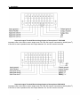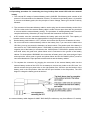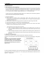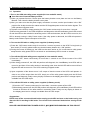
1
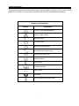
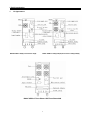
Uninterruptible Power System-UPS ON LINE 6K(S)/7.5K(S)/10K(S) 10KS(3P)/15KS(3P)/20KS(3P) USER MANUAL 1 Please comply with all warnings and operating Instructions in this manual and on the unit strictly. Save this manual properly. Do not operate this unit without reading thoroughly all safety information and operating instructions carefully. SEE INSTALLATION INSTRUCTIONS BEFORE CONNECTING TO THE SUPPLY 2 Table of contents 1. Brief introduction 1.1 System and model description…………………………………………………….…..…3 1.2 Description of commonly used symbols…………………………………………….…..4 1.3 Appearance………………………………………………………………………….……..5 1.4 Product specification and performance………………………………………………….6-8 General specification Electric performance Operating environment 2. Installation 2.1 Unpacking & Inspection…………………………………………………………………..9 2.2 Input and output power chords and protective earth installation…………………….9-11 2.3 Operating procedure for connecting long backup time model UPS with the external battery…………………………………………….…………….12 2.4 Parallel operation…………………………………………………………………………13 3. Operation and operating mode 3.1Operation………………………………………………………………………….……….14 3.2Operating mode……………………………………………………………………………15-18 4. Battery maintenance………………………………………………………………………..18 5. Notes for battery disposal and battery replacement………………………………….19 6. Trouble shooting…………………………………………………………………………….20-21 Appendix 1 Display panel…………………………………………………………………… 22 Appendix 2 The corresponding form of the LED display………………………………… 23-24 3 1. Brief introduction System and model description This Online Series is an uninterruptible power supply incorporating double-conversion technology. It provides perfect protection specifically for computer equipment communication Systems to computerized instruments. Its true online double-conversion design eliminates all mains power disturbances. A rectifier converts the alternating current from the utility power to direct current. This direct current charges the batteries and powers the inverter. On the basis of this DC voltage, the inverter generates a pure sinusoidal AC voltage, which is constantly powering the loads. Computers and Peripherals are thus powered entirely by the UPS. In the event of power failure, the maintenance-free batteries power the inverter. This manual is applicable to the following models: 1) The CR6K is a standard model with inbuilt battery, hereinafter called 6K; 2) The CR6KS is a long backup time model, which is able to connect with the external battery bank, hereinafter-called 6KS; 3) The 3CR6K is a standard model with inbuilt battery, hereinafter called three-phase 6K. 4) The 3CR6KS is a three-phase input and single-phase output long backup time model, which is able to connect with the external battery bank. Hereinafter called three-phase 6KS. 5) The CR7.5K is a standard model with inbuilt battery, hereinafter-called 7.5K; 6) The CR7.5KS is a long backup time model, which is able to connect with the external battery bank, hereinafter-called 7.5KS; 7) The 3CR7.5K is a standard model with inbuilt battery, hereinafter-called three-phase 7.5K. 8) The 3CR7.5KS is a three-phase input and single-phase output long backup time model, which is able to connect with the external battery bank. Hereinafter called three-phase 7.5KS. 9) The CR10K is a standard model with inbuilt battery, hereinafter-called 10K; 10) The CR10KS is a long backup time model, which is able to connect with the external battery bank, hereinafter-called10 KS; 11) The 3CR10K is a standard model with inbuilt battery, hereinafter-called three-phase 10K; 12) The 3CR10KS is a three-phase input and single-phase output long backup time model, which is able to connect with the external battery bank. Hereinafter called three-phase 10KS. 13) The 3CR15KS is a three-phase input and single-phase output long backup time model, which is able to connect with the external battery bank. Hereinafter called three-phase 15KS. 14) The 3CR20KS is a three-phase input and single-phase output long backup time model, which is able to connect with the external battery bank. Hereinafter called three-phase 20KS. 4 1. Brief introduction 1.2 Description of commonly used symbols The following symbols will be used in this manual and may appear during the course of your practical applications. Therefore, all users should be familiar with them and understand their meanings. Notation and Explanation Notation Explanation Alert you to pay special attention Caution of high voltage Turn on the UPS Turn off the UPS Idle or shut down the UPS Alternating current source (AC) Direct current source (DC) Protective ground Alarm silence Overload indication Battery check Recyclable Do not dispose with ordinary trash 5 1. Brief introduction 1. 1.3 Appearance BACK VIEW of 6K(S)/ Three Phase 6K(S) BACK VIEW of 7.5K(S)/10k(S)/Three Phase 7.5K(S)/10K(S) BACK VIEW of Three Phase 15K/Three Phase 20K 6 1. Brief introduction 1.4 Product specification and performance General specification (Standard Models) Model Power Rating 6K 6KS 7.5K 7.5KS 10K 10KS 4.2KW 4.2KW 5.25KW 5.25KW 7KW 7KW Frequency (Hz) Input Voltage(VAC) Current Battery 220±20% 31A max 31A max 38A max Voltage Current Output 50/60 24A max 24A max 30A max 90 35 91 Battery Output 7.5KVA/5.25KW (380~400)±20% 31A max 24A max 0.7 260×570×717 90 / (37) Battery Three-phase 15KS Three-phase 20KS 10KVA/7KW 15KVA/10.5KW 20KVA/14KW Output 50/60 (380~400)±20% 50A max 75A max Voltage Current 100A max 240VDC 40A max 60A max Voltage(VAC) 80A max (220~230)±2% PF 0.7 Dimension (W×D×H)mm Weight (kg) 91 / (39) Three-phase 10K (S) Voltage(VAC) Current 30A max (220~230)±2% Frequency (Hz) Input 38A max 240VDC Dimension (W×D×H)mm Power Rating 38 50/60 PF Model 93 6KVA/4.2KW Voltage(VAC) Weight (kg) 36 Three-phase 7.5K (S) Voltage Current 40A max Three-phase 6K (S) Voltage(VAC) Current 40A max 260×570×717 Frequency (Hz) Input 30A max 0.7 Dimension (W×D×H)mm Power Rating 50A max (220~230)±2% PF Model 50A max 240VDC Voltage(VAC) Weight (kg) 38A max 260×570×717 93 / (39) 55 7 55 1. Brief introduction Electrical performance Input Model Frequency Voltage 6K(S)/7.5K(S)/10K(S) Three-phase 6K(S)/7.5K(S)/10K(S)/15KS/20KS 50Hz 60Hz Power Factor Single-phase ±4Hz >0.98(Full load) Three-phase ±4Hz >0.95(Full load) Output Voltage Regulation ±1% Power Factor Frequency tolerance. 0.7lag Synchronized ±4Hz in Line mode (AC mode) ±0.1% of normal frequency in Battery mode Distortion Overload capacity Current crest rating THD<2% Full load (Linear Load) 105%-130% load transfers to bypass mode after 10 minutes >130% load transfers to bypass mode after 1 second and shutdown the output after 1 minute 3:1 Maximum Operating environment Temperature Humidity Altitude Storage temperature 0℃-40℃ 20%-90% <1000m -15℃-40℃ Note: if the UPS is installed or used in a place where the altitude is above than 1000m, the output power must be derated in use, please refer to the following: Altitude(M) 1000 1500 2000 2500 3000 3500 4000 4500 5000 Derating power 100% 95% 91% 86% 82% 78% 74% 70% 67% 8 2.Installation 2.1 Unpacking and inspection 1) Unpack the packaging and check the package contents. The shipping package contains: A UPS A user manual A communication cable A battery cable (for 6KS/7.5KS/10KS only) 2) Inspect the appearance of the UPS to see if there is any damage during transportation. Do not turn on the unit and notify the carrier and dealer immediately if there is any damage or lacking of some parts. 2.2 Input and output power chords and protective earth ground installation 1、Notes for installation 1) The UPS must be installed in a location with good ventilation, far away from water, inflammable gas and corrosive agents. 2) Ensure the air vents on the front and rear of the UPS are not blocked. Allow at least 0.5m of space on each side. 3) Condensation to water drops may occur if the UPS is unpacked in a very low temperature environment. In this case it is necessary to wait until the UPS is fully dried inside out before proceeding installation and use. Otherwise there are hazards of electric shock. 2、Installation Installation and wiring must be performed in accordance with the local electric code and the following instructions by professional personnel. For safety, please cut off the mains power switch before installation. The battery breaker also needs to be cut off if it is a long backup time model (“S” model). 1) Open the terminal block cover located on the rear panel of the UPS, please refer to the appearance diagram. 2) For 6K(S) UPS, it is recommended to select the UL 1015 10AWG(6mm2)wire or other insulated wire which complies with AWG Standard for the UPS input and output wirings. 9 2.Installation The protective earth ground wire refers to the wire connection between toe equipment which consumes electric equipment and the ground wire. The wire diameter of protective earth ground wire should be at least as above mentioned for each model and green wire of green wire with yellow ribbon wire is used. 1) After having completed the installation, make sure the wiring is correct. 2) Please install the leak current protective breaker at the output power distribution panel of the UPS if necessary. 3) To connect the load with the UPS, please turn off all the loads first, then perform the connection and finally turn on the loads one by one. 4) No matter the UPS is connected to the utility power or not, the output of the UPS may have electricity, The parts inside the unit may still have hazardous voltage after turning off the UPS. To make the UPS have no output, power off the UPS, and then disconnect the utility power supply. 5) Suggest charging the batteries for 8 hours before use. After connection, turn the input breaker in the “ON” position, the UPS will charge the batteries automatically. You can also use the UPS immediately without charging the batteries first, but the backup time may be less than the standard value. 6) If it is necessary to connect the inductance load such as a monitor or a laser printer to the UPS. the start-up power should be used for calculating the capacity of the UPS, as its start-up power consumption is too big when it is started. Input and output Terminal Block wiring diagram of 6K(S)/7.5K(S)/10K(S) Important notes: If the UPS is used in single mode, JP1 and JP2 must be connected by 10AWG (6mm2). If the UPS is used in parallel mode, the Jumper between JP1 and JP2 must be removed. 10 2.Installation Input and output Terminal Block wiring diagram of three-phase 7.5KS/10KS Important notes: If the UPS is used in single mode, JP1 and JP2 must be connected by 10AWG (6mm2). If the UPS is used in parallel mode, the Jumper between JP1 and JP2 must be removed. Input and output Terminal Block wiring diagram of three-phase 15KS/20KS Important notes: If the UPS is used in single mode, JP1 and JP2 must be connected by 6AWG (25mm2). If the UPS is used in parallel mode, the Jumper between JP1 and JP2 must be removed. 11 2.Installation 2.3 Operating procedure for connecting the long backup time model UPS with the external battery 1、The nominal DC voltage of external battery pack is 240VDC. Each battery pack consists of 20 pieces of 12V maintenance free batteries in series. To achieve longer backup time, it is possible to connect multi-battery packs, but the principle of “same Voltage, same type” should be strictly followed. 2、The connector of the external battery cable is used to plug into the external battery socket of the UPS. the other end of the external battery cable is made of three open wires with ring terminals to connect with the external battery pack(s). The procedure of installing battery bank should be complied with strictly. Otherwise you may encounter the hazardous of electric shock. 1) A DC breaker must be connected between the battery pack and the UPS. The capacity of breaker must be not less than the data specified in the general specification. 2) Set the battery pack breaker in “OFF” position and connect the 20 pieces of batteries in series. 3) You must connect the external battery cable to the battery first, if you connect the cable to the UPS first, you may encounter the hazardous of electric shock. The positive pole of the battery is connected to the 7.5KS/10KS/3 phase 7.5KS/10KS in parallel with blue and brown wires; the negative pole of the battery is connected to the 10KS/3 phase 7.5KS/10KS in parallel with black and white wires; the green and yellow ribbon wire is connected to the ground of the battery cabinet. For three-phase 15KS/20KS, the connection of battery wire is the same as that of input and output wire, and a green or green and yellow ribbon wire UL1015 6AWG (25mm2) must be connected between the input protective earth terminal and the battery cabinet. 3、To complete the connection by plugging the connector of the external battery cable into the external battery socket of the UPS. Do not attempt to connect any loads to the UPS now. You should connect the input power wire to the right position first, And then set the breaker of the battery pack in the ON position. After that set the input breaker in the ON position, The UPS begins to charge the battery packs at the time. the external battery cable diagram for 6KS/7.5KS/10KS(The cable may vary from different “S” models) 12 2.Installation 2.4 Parallel operation 1、Brief introduction of the redundancy N+X is currently the most reliable power supply structure. N represents the minimum UPS number that the total load needs; X represents the redundant UPS number .l. e. the fault UPS number that the system can handle simultaneously. The bigger the X is, the higher reliability of the power system is. For occasions where reliability is highly depended on, N+X is the optimal mode. As long as the UPS is equipped with parallel cables, up to 3 UPSs can be connected in parallel to realize output power sharing and power redundancy. 1、 Parallel installation 1) Users need to a standard 25-pin communication cable, which should have 25 cores, corresponding stitches and shield, as the UPS parallel cable. The length of the parallel cable is appropriate to less than 3 m. 2) Strictly follow the stand-alone wiring requirement to perform the Input wiring of each UPS. 3) Connect the output wires of each UPS to an output breaker panel. 4) Disconnect the Jumper on JP1 and JP2 of the terminal block first, and connect each output breaker to a main output breaker and then to the loads. The requirement of the output wiring is as follows: When the distance between the UPSs in parallel and the breaker panel is less than 20 meters, the difference between the wires of input & output of the UPSs is required to be less than 20%: When the distance between the UPSs in parallel and the breaker panel is greater than 20 meters, the difference between the wires of input & output of the UPSs is required to be less than 10% 2、Operation and maintenance 1) To perform the general operation, follow the stand-alone operating requirement; 2) Startup: The units transfer to INV mode simultaneously as they start up sequentially in utility power mode: Shutdown: the units shut down sequentially in INV mode. When the last one completes the shutdown action, each unit will shut down the inverter simultaneously and transfer to bypass mode. ※ Parallel Installation diagram It is easy to operate the equipment, with no previous training. You just need to read through this manual and operate according to the instructions in it. The meaning of the LED indicators. Please refer to the appendix 1 “Display panel” 13 3.Operation and Operating mode 3.1 Operation 1.Turn on the UPS with utility power supplied(in Line mode/AC mode) ※ Your first use of Internal Battery models. 1) When you operate first time, Please open the battery breaker cover plate and turn on the Battery Breaker. Then close the battery breaker cover plate. 2) After you make sure that the power supply connection is correct, set the input breaker in the “ON” position first. At this time the fan rotates and the UPS supplies power to the load via the bypass. The UPS operates in Bypass mode. 3) To power on the UPS by simply pressing the “ON” button continuously for more than 1 second. 4) When being powered on, the UPS will perform self-diagnosis, with the load/battery level LEDs turned on and then off one after another in ascending order. A few seconds later, the INV LED is turned on, the UPS is already running in Utility Power mode. If the utility power is abnormal, the UPS will operate in battery mode without output interruption of the UPS. 2. Turn on the UPS with on utility power supplied (in battery mode) 1) Press the “ON” button continuously for more than 1 second to power on the UPS For long back up time model (“S” model), please make sure that the battery breaker is in “ON” position. 2) During the course of starting up, the UPS has the same action as if it is connected to utility power except that the utility power LED is not turned on and the battery LED is turned on instead. 3. Turn off the UPS with utility power supplied (in Line mode/AC mode) 1) Press the “OFF” button continuously for more than 1 second to turn off the inverter of the UPS immediately. 2) When being powered off, the UPS will perform self-diagnosis, the Load/Battery level LEDs will be turned on and then off one after another in ascending order, then the INV LED will be turned off and Bypass LED will be turned on. The UPS is working in Bypass mode. 3) Upon completion of the above to turn it off, output of electric current of the UPS is still present. In order to cut off the output from the UPS, simply cut off the utility power supply and the UPS will perform self-diagnosis, finally not any display is shown on the display panel and no voltage output is available from the UPS output. 4. Turn off the UPS with on utility power supplied (in Battery mode) 1) Press the “OFF” button continuously for more than 1 second to power off the UPS. 2) When being powered off, the UPS will perform self-diagnosis, the Load/Battery level LEDs will be turned on and then off one after another in ascending order. Finally not any display is shown on the display panel and on voltage is available form the UPS output. Suggestions: Please turn off the connected loads before turning on the UPS and turn on the loads one by one after the UPS is working in INV mode. Turn off all of the connected loads before turning off the UPS. ISOLATE UNINTERRUPTIBLE POWER SUPPLY(UPS)BEFORE WORKING ON THIS CIRCUIT 14 3.Operation and Operating mode 3.2 Operating mode(LED display mode) 1. Utility power mode The display panel in utility power mode is shown in the following diagram, The utility power LED and the INV LED are turned on, The load level LEDs will be turned on in accordance with the load capacity connected. 1) If the battery LED is turned on and the utility power LED flashes, it indicates the voltage or frequency of the utility power has exceeded the normal range, the UPS operates in battery mode. Fig-3-1 The utility power mode 2) If output overloaded, the load level LEDs will be turned on and alarm will keep twice every second. You should get rid of some unnecessary loads one by one to decrease the loads connected to the UPS less than 90% of its nominal power capacity. Note: Please follow the following steps to connect the generator: Activate the generator and wait until the operation is stable before supplying power of the generator to the UPS (be sure that the UPS is in idle mode). Then turn on the UPS according to the start-up procedure. After the UPS is turned on, then the loads can be connected to the UPS one by one. The power capacity of the AC generator should be at least twice of the UPS capacity. 2. Battery mode The display panel in battery mode is shown in the following diagram Fig.3-2. The battery LED and the INV LED are turned on. The displayed number of the battery level LEDs will be turned on in accordance with the battery capacity. Note that the load level LEDs in utility power mode will indicate the level of the battery capacity in battery mode instead. 1) When the UPS is running in battery mode, the buzzer beeps once every 4 again, The buzzer will stop beeping (in silence mode). Press the “ON” button once again for more than 1 second to resume the alarm function. Fig 3-2 Battery mode diagram 15 3.Operation and Operating mode 2) When the battery capacity decreases, the number of the battery capacity LEDs turned on will be reduced. If the battery voltage descends to the alarm level, the buzzer will beep once every second to remind the users of in sufficient battery capacity and the UPS is soon going to shut down automatically. Then the load operations should be carried out promptly and the loads should be eliminated one by one. 3. Bypass mode The display panel in bypass mode is shown in the following diagram Fig.3-3. The utility power LED and the bypass LED are lit. The displayed number of the load LEDs will be turned on in accordance with the load capacity connected. The UPS will beep once every 2 minutes in bypass mode. The utility power LED flashes. it shows that the voltage or frequency of the utility power has exceeded the normal range of the UPS. Fig 3-3 UPS bypass mode diagram Other indications on the display panel are the same in utility mode. The UPS does not have the backup function when it is in bypass mode. The power used by the load is supplied from the utility power via internal filter. 4. Abnormality mode In case the fault LED is turned on when the UPS is in use, it shows that the UPS is operating in abnormal mode. Please refer to the troubleshooting in section 6 for derail. 5. Backup time for the standard model The backup time of the long backup time model is dependent on the external battery pack capacity and the load level as well as other factors. The backup time of standard model may vary from different models and load level, Please refer to the following: 16 3.Operation and Operating mode Load Capacity 6KVA BACKUP TIME CURVE Load Capacity 7.5KVA/10KVA BACKUP TIME CURVE 6. Communication port Intelligent slot This series is equipped with an intelligent slot for Web power (optional accessory) or other optional card to achieve remote management of the UPS through internet / intranet. Please contact your local distributor for further information, RS232 Interface 1) The following are the descriptions and pin assignment of RS232 DB-9 port: Baud rate: 2400bps Data bit: 8 bit Ending bit:1 bit Parity bit: None DB-9 pin assignment: Pin number Function description I/O 3 Rx Input 2 Tx Output 5 Ground GND 17 RS232 Interface 3.Operation and Operating mode Optional AS400 interface This optional AS400 card provides dry contact closure signal “OPEN” or “CLOSE”. Following are the pin assignment and the descriptions of As400 card: PIN1:UPS failure (normally open, active close) PIN2:summary PIN3:ground PIN4:Remote shutdown PIN5:Common PIN6:Bypass active(relay close) PIN7:Battery low PIN8:UPS On (relay close) PIN9:Utility Power failure(normally open, active close) AS400 Interface 4. Battery maintenance This series UPS only requires minimal maintenance. The battery used for standard models are value regulated sealed lead-acid maintenance free battery. These models require minimal repairs. The only requirement is to charge the UPS regularly in order to maximize the expected life of the battery. When being connected to the utility power, whether the UPS is turned on or not, the UPS keeps charging the batteries and also offers the protective function of overcharging and over discharging. The UPS should be charged once every 4 to 6 months if it has not been used for a long tine. In the regions of hot climates, the battery should be charged and discharged every 2 months. The standard charging time should be at least 12 hours. Under normal conditions, the battery life lasts 3 to 5 years. In case if the battery is found not in good condition, earlier replacement should be made. Battery replacement should be performed by qualified personnel. Replace batteries with the same number and same type of batteries. Do not replace the battery individually. All the batteries should be replaced at the same time following toe instructions of the battery supplier. Normally, the batteries should be charged and discharged once every 4 to 6 months. Charging should begin after the UPS shuts down automatically in the course of discharging, the standard charging time for the standard UPS should be at least 12 hours. 18 5. Notes for battery disposal and battery replacement 1) Before disposing of batteries, remove conductive jewelry such as necklace, wrist watches and rings. 2) If it is necessary to replace any connection cables, please purchase the original materials from the authorized distributors or service centers, so as to avoid overheat or spark resulting in fire due to insufficient capacity. 3) Do not dispose of batteries or battery packs in a fire, they may explode. 4) Do not open or mutilate batteries, released electrolyte is highly poisonous and harmful to the skin and eyes. 5) Do not short the positive and negative of the battery electrode, otherwise, it may result in electric shock or fire. 6) Make sure that there is no voltage before touching the batteries, The battery circuit is not isolated from the input potential circuit. There may be hazardous voltage between the battery terminals and ground. 7) Even though the input breaker is disconnected, the components inside the UPS are still connected with the batteries, and there are potential hazardous voltages. Therefore, before any maintenance and repairs work is carried out, switch off the breaker of the battery pack or disconnect the jumper wire of connecting between the batteries. 8) Batteries contain hazardous voltage and current. Battery maintenance such as the battery replacement must be carried out by qualified personnel who are knowledgeable about batteries. No other persons should handle the batteries. 19 6. Troubleshooting Problem Possible cause Solution The #1 Fault LED and the The UPS shutdown due to #6 LED are turned on, the internal overheat buzzer beeps continuously Make sure the UPS is not overloaded; the air vents are not blocked and the ambient temperature is not too high. Wait for 10 minutes for the UPS to cool down before turning on again. If failed, please contact the distributor or service center. The #1 Fault LED and the The UPS output is short #2 and #5 LED are turned circuited. on, and the buzzer beeps continuously Turn off the UPS. Remove all the loads. Ensure that the load is not failed or the UPS has no internal faults before turning it on again. If failed, please contact the distributor or service center. The #1 Fault LED and the The UPS shuts down due #4 LED are turned on, the to its internal fault. UPS beeps continuously Please contact the distributor or service center. The #1 Fault LED and the The UPS shuts down due #5 LED are turned on, the to its internal fault. UPS beeps continuously Please contact the distributor or service center. The #1 Fault LED and the Overcharging protection #3 LED are turned on, the UPS beeps continuously The charger of the UPS is failed. Please contact the distributor or service center. The utility flashes The voltage or frequency of the utility power is out of the input range of the UPS The UPS is running in battery mode. To save your data and close the application program. Make sure the utility power is within the input voltage or frequency range permitted by the UPS. The #1 Fault LED and the The UPS is overloaded or #2 LED are turned on, the the load equipment is UPS beeps continuously faulty Check the loads and remove all non-critical equipment. Recalculate the load power and reduce the number of loads connected to the UPS. Check that the loads are not failed. The #1 Fault LED and the The charge of the UPS is battery LED are turned on, defective. the buzzer beeps every second Please contact the distributor or service center. Battery LED flashes Battery low or battery not connected Check the battery. If the battery is damaged, replace the battery immediately and ensure that the battery breaker is in “ON” position. The utility power is normal, but the UPS can not turn in line mode Bypass breaker in “OFF” position Set the bypass breaker in “ON” position power LED 20 6. Troubleshooting Problem Possible cause Solution Battery discharging time diminishes Battery not yet been fully charge Keep UPS connected to utility power persistently for more than 10 hours to recharge the batteries again. UPS overloaded Check the loads and remove the non-critical equipment. Battery aged Replace the batteries. Please contact the distributor to obtain the parts and replacement service. The UPS cannot power The “ON” button is on after pressing the ON pressed too briefly button The UPS is not connected to the battery or the battery pack voltage is too low. UPS fault Press the “ON” button for more than 1 second. Check the battery or recharge the battery. Please connect the distributor or service center. When you contact the service center, please provide the following information: ● ● ● Model No. and the serial No. of the UPS; The date when the problem arose; Complete description of the problem, including the LED display, alarm warning, and power condition and load capacity. If your UPS is a long backup time model, you may also provide the battery information. 21 Appendix 1 Display Panel ● Power ON/OFF: To turn on the UPS simply by pressing the “ON” button on the front panel continuously for 1 second. Press the “OFF” button on the front panel continuously for 1 second to turn off the UPS. ● Bypass LED (orange LED): Whenever the bypass LED is turned on, it shows that the loading current is supplied directly from the utility power. ● Utility power LED (green LED): Whenever the utility power LED is turned on, it shows that the utility power is normal. ● Inv LED (green LED): Whenever the INV LED is turned on, it shows that the loading current is supplied from utility power or battery via the inverter. ● Battery LED (orange LED): Whenever the battery LED is turned on, it shows that the loading current is supplied from battery via the inverter. ● Fault LED (red LED): Whenever the fault LED is turned on, it shows that the UPS is in abnormal condition. ● #2-#6 LEDs (the #2 LED is orange and the #3-#6 LEDs are green): These LEDs indicate the percentage of the load capacity in utility power mode or battery capacity level in battery mode. 22 Appendix 2 The corresponding form of the LED Display LED display No. 1# 1 0~35% Load capacity 2 36~55% Load capacity 3 Utility Power Mode 2# 3# 8# 9# none none none none none 56~75% Load capacity 4# 5# 6# 4 76~95% Load capacity 5 96~105% Load capacity 6 0~20% Battery capacity 7 21~40% Battery capacity 41~60% Battery capacity 9 61~80% Battery capacity 10 81~100% Battery capacity ↑ ↑ ↑ ↑ 8 Alarm warning Operating state Battery Mode 11 Bypass mode 12 Overloaded in utility mode and UPS still in INV mode 13 Overloaded in utility mode and UPS still in bypass mode 14 Utility power abnormal 15 Overloaded in battery mode, Early-warning ↑ ↑ ↑ ↑ ↑ ↑ ↑ ↑ 23 7# 10# Beep once every sec. Beep once every 4 sec. Beep once every 4 sec. Beep once every 4 sec. Beep once every 4 sec. Beep once every 2 min. ↑ Beep twice every sec. Sustained beep ↑ ↑ ↑ Beep twice every sec. Appendix 2 The corresponding form of the LED Display 16 Overload in battery mode, Cut off the output 17 Over temperature 18 Inv abnormal 19 Output short circuited 20 BUS voltage abnormal 21 Charger or battery failed 22 Battery voltage abnormal ↑ 23 BAT SCR failed 24 Fan abnormal 25 Bypass STS failed 26 INV RLY failed 27 Communication abnormal Continuously beep ↑ ↑ Continuously beep ↑ ↑ Continuously beep ↑ ↑ Continuously beep ↑ ↑ Continuously beep ↑ ↑ Continuously beep ↑ ↑ ↑ ↑ ↑ Continuously beep Continuously beep Sustained beep Sustained beep ↑ ↑ Sustained beep :Solid ON : Flash ↑: LED display and alarm warning are dependent on other conditions. 24