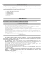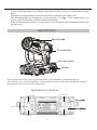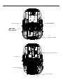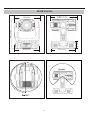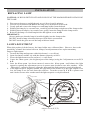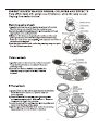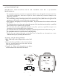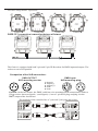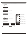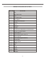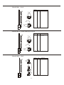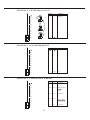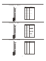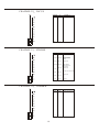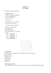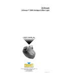
1
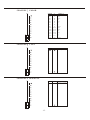
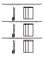
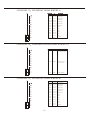
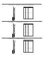
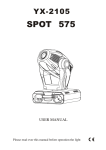
INTRODUCTION
This equipment is produced in accordance with CE standards and conforms to the
international standard DMX512 protocol.
On receiving this product, please carefully check that there has been no damage caused in
transportation and that the following parts are enclosed:
1
1
1
1
2
1200W SPOT MOVING HEAD
SIGNAL CABLE
USER MANUAL
SAFETY CABLE
CLAMPS
IMPORTANT
BEFORE OPERATION PLEASE CONFIRM THAT THE POWER SUPPLY STATED ON THE REAR
PANEL OF THIS UNIT IS THE SAME AS THE SUPPLIED MAINS POWER IN YOUR AREA.
READ THIS USER MANUAL CAREFULLY BEFORE OPERATION
SAFETY WARNING
Ø
Ø
Ø
Ø
This product must be installed by a qualified professional
All operation and maintenance must be carried out in accordance with this user manual.
Keep this device away from any form of water or moisture at all times.
Always disconnect the power before attempting to open the equipment housing or carrying
out any maintenance.
Ø Avoid looking directly into the light source (especially those who suffer from epileptic fits)
Ø DO NOT touch the equipment casing during operation due to high temperatures of the metal
and plastic housing.
Ø This equipment is designed for indoor use only.
ATTENTION
Ø This product left our premises in perfect condition. In order for safe operation and to
maintain the original condition, the user must always follow the instructions and safety
warnings described in this user manual.
Ø The manufacturer cannot accept liability for any resulting damages caused by nonobservance of this manual or any unauthorized modifications to the equipment and are not
subject to warranty.
Ø Always make sure that the equipment is OFF before connecting the power cables.
Ø Always make sure that the power cable is never cut or damaged by sharp edges. It is
advisable to check the state of the power cable from time to time.
Ø DO NOT connect this equipment to a dimmer rack.
Ø This device falls under Protection Class I. Therefore it is essential that the yellow/green
wire must be earthed.
Ø If during transportation or storage the equipment has gone through drastic temperature
changes, it is advisable to allow some time for the equipment to first adjust to room
temperature before operation.
Ø Never turn on the equipment without a lamp
Ø Avoid shaking of strong impacts to the equipment.
.1.
Ø Never lift the equipment by holding it at the head or arms. Always use the handles on the
base.
Ø DO NOT turn on the lamp at short intervals as this will reduce the lamp's life.
Ø The maximum ambient temperature of the housing is ta=45 . If the temperature is in
excess of this the thermal switch will shut off the power.
Ø When transferring the product, it is advisable to use the original packaging that the unit left
the factory in.
DESCRIPTION
Moving head
Tilt lock button
Pan lock button
Handel
The head must be locked for transportation-the tilt lock button is pushed and the pan
lock/unlock lever is in lock position. To unlock the head, press the tilt unlock button and move
the pan lock/unlock lever to unlock position.
REAR PANEL OF THE BASE
5 Pin DMX output
Live fuse holder
Power switch
Power cord
5 Pin DMX input
.2.
Color wheel 2
Lamp chamber
Inside fresnel lens
Ignitor
Thermostat
Lamp cover
.3.
DIMENSIONS
585 mm
506 mm
489 mm
151 mm
602 mm
525mm
.4.
INSTALLATION
REPLACING LAMP
CAUTION: ALWAYS SWITCH OFF AND UNPLUG AT THE MAINS BEFORE INSTALLING
THE LAMP
1. Disconnect the power and all the unit to cool for at least 10 minutes.
2. Loosen screws indicated A & B on the lamp cover at the back of the head.
3. Gently pull and remove the lamp cover and lamp holder from the head.
4. Holding the lamp by its ceramic base, carefully pull the lamp straight out of the lamp socket.
5. Holding the new lamp by its ceramic base, gently insert the lamp in to the lamp socket.
6. Reinsert the lamp cover and lamp holder and tighten screw A & B.
IMPORTANT:
Ø Always make sure that the lamp is installed tightly into the lamp socket.
Ø DO NOT install a lamp other than that specified in this user manual.
Ø DO NOT touch the glass area of the lamp with bare hands.
LAMP ADJUSTMENT
When this product left the factory, the lamp holder was calibrated here. However, due to the
possibility of small deviations between lamps, fine adjustments after replacement may
improve light output.
1. Turn on the lamp and operate with white beam (i.e. no effects)
2. Open the shutter and the iris with the dimmer intensity at 100%.
3. Focus the light beam on a flat surface (i.e. wall/floor)
4. Center the hot-spot (the brightest part of the image) using the 3 adjustment screws X, Y
& Z.
5. Once the hot-spot
has been centered, remove the
hot-spot
and balance the light
output by turning the adjustment screws a quarter-turn clockwise one after another. If the
hot-spot cannot be located, adjust the lamp until the light output is evenly distributed.
6. If the light output is brighter around the edge than in the center or if the light output is too
low, the lamp is too far back from the reflector. Turn the screws X, Y & Z a quarter-turn
anti-clockwise one after another until the light output is evenly distributed.
Lamp
Lamp holder
Fixed the lamp holder
of screw(A,B)
Disconnect the fixture from AC power before re-lamping.
Lamp is hot! Risk of fire! Protect hands and eyes.
Wait at least 15min. before opening
the covers and removing
lamp from the fixture.
Adjust screw (X,Y,Z)
.5.
.6.
R IGGING THE FIXTURE
I M P O R TA N T : I N S T A L L AT I O N M U S T B E C A R R I E D O U T B Y A Q U A L I F I E D
PROFESSIONAL.
Ø The equipment must be mounted on equipment the has been designed and constructed in a
way that can withhold 10 times the weight for 1 hour without any structural damage to the
supporting structure.
Ø The installation must always be secured with a second safety attachment, e.g. safety cable.
This secondary safety attachment must be connected in a way that allows no part of the
equipment to fall to the ground if the main attachment fails.
Ø When rigging, derigging or servicing the fixture, all persons must clear the area below the
work place.
Ø The user must have the safety and technical aspects of the installation checked by a qualified
professional before commencing operation.
Ø The user must have the equipment checked every four years by a qualified expert or in
accordance to local health and safety regulations.
Ø The user must have the installation checked by a qualified professional at least once a year.
Ø The equipment must be installed out of reach of people.
Ø The equipment must never be mounted swinging freely.
Ø This device can be placed directly on the stage floor or rigged in any orientation on a truss
without altering its operating characteristics.
Mounting using the Omega-Holder:
1)Bolt each clamp to the omega holder with a M12
bolt.
2)Attach the Omega-Holder to the bottom of the
base by inserting both screw bolts into the base
and tightening clockwise.
3)Connect the safety cable through the two holes
in the bottom of the base and to the truss.
Clamp
Secure chain
Omega-holde
.7.
5
Possible omega holder 4 positions:
DMX-512 connection/connection between fixtures
120
The fixture is equipped with both 3-pin and 5-pin XLR sockets for DMX input and output. The
sockets are wired in parallel.
Occupation of the XLR-connection:
DMX-input
XLR mounting-plug:
DMX-OUTPUT
XLR mounting-socket:
1- Ground
2 - Signal (-)
3 - Signal (+)
4 - Free
5 - Free
Caution: At the last fixture, the DMX-cable has to be terminated with a terminator. Solder a
120 resistor between Signal (-) and Signal (+) into a 3-pin XLR-plug and plug it in the
DMX-output of the last fixture.
The transform of the controller line of 3 pins and 5 pins (plug and socket)
.8.
CONTROL PANEL
Current DMX address
001
MODE
DMX ADDRESS
Press UP/DOWN key to select
DMX address(000-489 )
MODE
PAN REVERSE
Press UP/DOWN key to select YES
(inver t direction)/NO(normal direction)
MODE
TILT REVERSE
Press UP/DOWN key to select YES
(inver t direction)/NO(normal direction)
PAN
MODE
Press ENTER to display the current PAN
movement range. Press UP/DOWN key to adjust
the PAN(0 ~54 0 ) movement range.
UP/DOWN
RESET
Press enter for complete
reset of equipment
TILT
UP/DOWN
MODE
LAMP
Press ENTER to display the current SHUTTER
key to adjust the
Press UP/DOWN
SHUTTER setting.
SHUTTER setting
Press UP/DOWN to turn lamp on/off
UP/DOWN
MODE
DIMMER
BACKLIGHT
Press ENTER to display the current TILT
movement range. Press UP/DOWN key to adjust
the TILT(0 ~280 ) movement range.
Press UP/DOWN to turn backlight on/off
Press ENTER to display the current DIMMER
setting. Press UP/DOWN key to adjust the
DIMMER setting
UP/DOWN
FOCUS
MODE
Press ENTER to display the current FOCUS
setting. Press UP/DOWN key to adjust the
FOCUS setting
UP/DOWN
Press ENTER to
software
SOFTWARE VERSION display
MANUAL
version
MODE
RUN MODE
UP/DOWM
ENTER
DMX
.9.
ENTER
ZOOM
Press ENTER to display the current ZOOM
setting. Press UP/DOWN key to adjust the ZOOM
setting
DMX512 CHANNEL FUNCTION
FUNCTION
CHANNEL
1
Pan
2
Pan micro-step
3
Tilt
4
Tilt micro-step
5
Scan Speed
6
Lamp ON/OFF & reset
7
Colour
8
Cyan
9
Magenta
10
Yellow
11
3200k color temperature rectification(cto)
12
CYM +CTO speed adjust
13
Gobo wheel A
14
Gobo rotation (gobo wheel A)
15
Gobo wheel B
16
G obo rotation(gobo wheel B)
17
Prism wheel
18
Prism rotation
19
Frost
20
Iris
21
Zoom
22
Focus
23
Strobe
24
Dimmer
.10.
CHANNEL1 PAN
VALUE
%
255
100
EFFECT
Clockwise 54 0
rotate
CHANNEL 2 PAN FINE( proportional )
VALUE
%
255
100
EFFECT
Fine control of pan
movement
CHANNEL3 TILT
.11.
VALUE
%
255
100
EFFECT
Tilt 280
rotate
CHANNEL 4 TILT FINE(proportional )
VALUE
%
EFFECT
Fine control of tilt
movement
CHANNEL 5 SCAN SPEED ADJUST
VALUE
%
EFFECT
Slow
Fast
CHANNEL 6 LAMP ON/OFF & RESET
VALUE
%
240~255 94~100
230~239
90~94
Lamp off after 3
140~229
55~90
No function
128~139 50~55
0~127
.12.
EFFECT
No function
0~50
Lamp on after 3
No function
CHANNEL 7 COLOR
VALUE
197~255
%
EFFECT
77~100 Rainbow effect slow to fast
182
71
Uv filter
169
66
6000kcto
156
61
Green
143
56
Orange
130
51
Blue
117
46
Red
104
41
Open/hole
83 ~ 97
32~28
Uv filter
69 ~ 82
27 ~ 32
6000kcto
56 ~ 68
22~27
Green
42 ~ 55
16~22
Orange
28 ~ 41
11~16
Blue
14 ~ 27
5~11
Red
0 ~ 13
0~5
Open/hole
VALUE
%
CHANNEL 8 CYAN
EFFECT
Full cyan (gradually)
CHANNEL 9 MAGENTA
VALUE
%
EFFECT
Full magenta (gradually)
.13.
CHANNEL 10 YELLOW
VALUE
%
EFFECT
Full yellow
(gradually)
CHANNEL 11 CONVERSION TEMPERATURE FILTER 3200K
VALUE
%
EFFECT
0~100% 6000K~3200K
CHANNEL 12
CMY+CTO CHANGE SPEED
VALUE
%
0
.14.
EFFECT
Slow
255
0
Fast
CHANNEL 13 ROTATING GOBO WHEEL A
VALUE
%
220~255
86.5~100
202 ~ 219
78.5~86.5 Shaking gobo 6
184 ~ 201
71.5 ~ 78.5 Shaking gobo5
EFFECT
Gobo flow effect
166 ~ 183
65 ~ 71.5
Shaking gobo4
148 ~ 165
57.5 ~ 65
Shaking gobo3
130 ~ 147
50.5 ~ 57.5 Shaking gobo2
112~ 129
43.5 ~ 50.5 Shaking gobo 1
96 ~ 111
37 ~ 43.5
Gobo 6
80 ~ 95
31 ~ 37.5
Gobo 5
64 ~ 79
25 ~ 31.5
Gobo 4
48 ~ 63
18.5 ~ 25
Gobo 3
32 ~ 47
18.5 ~ 25
Gobo 2
15 ~ 31
12 ~ 18.5
0 ~ 15
06 ~ 12
Gobo 1
Open/hole
CHANNEL 14 GOBO ROTATION(GOBO WHEEL A)
VALUE
159~255
61~158
0~60
%
EFFECT
62~100 Rotation gobo reverse
rotate from slow to fast
24~62
Rotation gobo rotate
from slow to fast
0~24
0~540 indexing
CHANNEL 15 ROTATING GOBO WHEEL B
.15.
VALUE
%
220~255
86.5~100
Gobo flow effect
202 ~ 219
78.5~86.5
Shaking gobo 6
184 ~ 201
71.5 ~ 78.5
Shaking gobo5
166 ~ 183
65 ~ 71.5
Shaking gobo4
148 ~ 165
57.5 ~ 65
Shaking gobo3
130 ~ 147
50.5 ~ 57.5
Shaking gobo2
112~ 129
43.5 ~ 50.5
Shaking gobo 1
96 ~ 111
37 ~ 43.5
Gobo 6
80 ~ 95
31 ~ 37.5
Gobo 5
64 ~ 79
25 ~ 31.5
Gobo 4
48 ~ 63
18.5 ~ 25
Gobo 3
32 ~ 47
18.5 ~ 25
Gobo 2
15 ~ 31
12 ~ 18.5
Gobo 1
0 ~ 15
06 ~ 12
EFFECT
Open/hole
CHANNEL 16
GOBO ROTATION(GOBO WHEEL B)
VALUE
159~255
61~158
0~60
CHANNEL 17
CHANNEL 18
%
EFFECT
62~100 Rotation gobo reverse
rotate from slow to fast
24~62
Rotation gobo rotate
from slow to fast
0~24
0~540 indexing
PRISM EFFECT WHEEL
VALUE
%
211~255
83~100
158~210
62~83
Stripe
105~157
41~62
3-facet prism
52~104
20~41
Diamante
0~51
0~20
Open/hole
EFFECT
5-facet prism
PRISM ROTATION
VALUE
133~255
.16.
%
EFFECT
52~100 Backwards effect rotation
from fast to slow
128~132
50~52
5~127
2~50
0~4
0~2
No rotation
Forwards effect rotation
from fast to slow
No rotation
CHANNEL 19 FROST
VALUE
234~255
CHANNEL 20
%
EFFECT
92~100 No function
212~233
83~92
pulse opening
190~211
74~83
pulse closing
180~189
70~74
100%forst
0~179
0~70
open
IRIS
VALUE
%
234~255
92~100
212~233
83~92
190~211
74~83
180~189
70~74
0~179
0~70
EFFECT
No function
Plug closing from max
to min
CHANNEL 21 ZOOM
VALUE
%
255
100
0
.17.
0
EFFECT
Min zoom
Max zoom
CHANNEL 22 FOCUS
VALUE
255
%
100
0
EFFECT
From far to near focus
0
CHANNEL 23 STROBE
VALUE
%
224~255
88~100
192~223
75~88
160~191
63~75
128~159
50~63
96~127
38~50
64~95
25~38
32~63
12~25
Open/hole
0~12
Shutter
0~31
CHANNEL 24
EFFECT
Open/hole
Random strobeeffect from slow
to fast
Open/hole
Pulse-effect in
sequences from
slow to fast
Open/hole
Strobe from slow to fast
DIMMER
.18.
VALUE
%
255
100
0
0
EFFECT
Dimmer intensity form
0% to 100%
8. Technical specifications
US-model: Voltage............................AC100/110/120V , 50/60Hz
Fuse................................ T 20 A@120V
EU-model:Voltage............................AC220/230/240V ,50/60Hz
Fuse ................................T10A @230V
Rated Power 1600W
DMX512 Channel 24CHS
Luminous
96000 LM
Lamp:
- MSR1200 SA GY 22
-Colour temperature 6000K
-Average lifespan:750hrs
Optical System:
- Focus: electronic linear focus
- Zoom: electronic zoom 13 ~42
-Dimmer: smooth dimmer 0~100%
-Strobe: Variable speed 1~10 flashes/sec (plus random strobe effect)
-Frost filter: smooth adjust 0~100%
-Iris: Electronic linear iris
Rotating gobo
-12 gobos (interchangeable)
-Gobo-flow effect
-Bi-directional rotation & 0 ~540
indexing
Colour wheel:
-6 dichroic-filters, UV, CTF 6000K plus white
rainbow -flow effect)
step/linear rotation(plus bi-directional
Rigging:
-Stands directly on the floor
-Mounts horizontally or vertically with 2 clamps
-2 truss orientation
-Safety chain/cord attachment bolt
Pan / Tilt Movement:
-Pan 530 , Tilt 280
-Micro-step scan effect
-Auto-repositioning by photoelectric repositioning system
-Linearity move speed adjust.
Prisms: 3-facet prism / 5-facet prism(dual direction rotation with adjustable speed)
Dimensions and weight:
-Length of base (including handles): 506 mm
-Width of yoke: 525 mm
-Height (head horizontal): 602 mm
-Weight (net): 60 kg
.19.
Beampath:
Beam angle 42 -max. zoom
² ¨ Ê Beam
ø Â ·
¾ ¶ 13
£ º- min. Zoom
angle
1840
19840
460
4960
115 Foot-candles
1240 LUX
205
2200
6
235
2530
59
630
5
3.84
10
7.68
26
280
15 Foot-candles
160 LUX
15
11.52
20 Distance(m)
15.38 Diameter(m)
Beam opening(m)
5
4
13
3
2
1
5
1.14
10
2.29
15
3.42
42
0
1
20 Distance(m)
4.56 Diameter(m)
2
3
4
5
6
Beam angle 42 with frost
Beam angle 13 with frost
369
3970
92
990
23 Foot-candles
250 LUX
40
440
7
65
705
16
175
5
4.66
10
9.33
4 Foot-candles
45 LUX
7
80
6
5
4
26
3
2
50
1
0
1
2
5
2.30
10
4.62
20 Distance(m)
9.2 Diameter(m)
15
6.93
3
4
5
6
7
Beam angle 13 with frost, distance=5m
20 Distance(m)
18.65 Diameter(m)
15
13.98
Beam angle 42 with frost, distance=5m
4000
372
(LUX)
(Foot-candles)
3000
279
600
56
2000
186
400
37
1000
93
200
19
0
1
0.8
0.6
0.4
0.2
0.2
0
Diameter(m)
0.4
0.6
0.8
1
74
800
0
(LUX)
0
.20.
2
(Foot-candles)
1.6
1.2
0.8
0.4
0.4
0
Diameter(m)
0.8
1.2
1.6
2
0
Maintenance and cleaning
It is absolutely essential that the fixture is kept clean and that dust, dirt and smoke-fluid
residues must not buildup on or within the fixture. Otherwise, the fixtures light-output will
be significantly reduced. Regular cleaning willnot only ensure the maximum light-output,
but will also allow the fixture to function reliably throughout its life.A soft lint-free cloth
moistened with any good glass cleaning fluid is recommended, under no circumstances
should alcohol or solvents be used!
DANGER :Disconnect from the mains before starting anymaintenance work
The front objective lens will require weekly cleaning as smoke-fluid tends to building up
residues, reducing thelight-output very quickly. The cooling-fans should be cleaned
monthly.
The gobos may be cleaned with a soft brush. The interior of the fixture should be cleaned at
least annually using a vacuum-cleaner or an air-jet.
The dichroic colour-filters, the gobo-wheel and the internal lenses should be cleaned
monthly.
To ensure a proper function of the gobo-wheel , we recommend lubrication in six month
intervals. The quantity of oil must not be excessive in order to avoid that oil runs out when
the gobo-wheel rotates.
There are no serviceable parts inside the device except for the lamp and the fuse.Please refer
to the instructions under "Fitting/Exchanging the lamp".Maintenance and service
operations are only to be carried out by authorized dealers.
Replacing the fuse
If the lamp burns out, the fine-wire fuse of the device might fuse, too. Only replace the fuse
by a fuse of same type and rating.Before replacing the fuse, unplug mains lead.
Procedure:
1) Unscrew the fuseholder on the rear panel of the base with a fitting screwdriver from the
housing (anti- clockwise).
2) Remove the old fuse from the fuseholder.
3) Install the new fuse in the fuseholder.
4) Replace the fuseholder in the housing and fix it.
.21.