1
CC-Link System
Spring Clamp Termnal Block Type
Repeater Hub Module
User’s Manual
AJ65BTS-RPH
Thank you for buying the Mitsubishi general-purpose programmable
controller MELSEC-A series.
Prior to use, please read both this manual and related manuals
thoroughly and familiarize yourself with the product.
MODEL
AJ65BTS-RPH-U
MODEL
CODE
13JP97
IB(NA)-0800346-C(1112)MEE
© 2006 MITSUBISHI ELECTRIC CORPORATION
zSAFETY PRECAUTIONSz
(Read these precautions before using.)
When using Mitsubishi equipment, thoroughly read this manual and the
associated manuals introduced in this manual. Also pay careful attention to safety
and handle the module properly.
The precautions given in this manual are concerned with this product. Refer to the
user's manual of the network system to use for a description of the network
system safety precautions.
In this manual, the safety precautions are classified into two levels:
"
WARNING" and "
CAUTION".
WARNING
Indicates that incorrect handling may cause
hazardous conditions, resulting in death or severe
injury.
CAUTION
Indicates that incorrect handling may cause
hazardous conditions, resulting in minor or moderate
injury or property damage.
Under some circumstances, failure to observe the precautions given under
"
CAUTION" may lead to serious consequences.
Observe the precautions of both levels because they are important for personal
and system safety.
Make sure that the end users read this manual and then keep the manual in a safe
place for future reference.
A-1
[Design Precautions]
WARNING
z Input/output could be switched on or off when a problem occurs in the
repeater module.
So build an external monitoring circuit that will monitor any input/output
signals that could cause a serious accident.
CAUTION
z Use the module in an environment that meets the general specifications
contained in this manual. Using this module in an environment outside the
range of the general specifications could result in electric shock, fire,
erroneous operation, and damage to or deterioration of the product.
z Do not install the control wires or communication cables together with the
main circuit or power wires.
Keep a distance of 100mm (3.94inch) or more between them.
Not doing so could result in malfunctions due to noise.
[Installation Precautions]
CAUTION
z Do not directly touch the module's conductive parts.
Doing so may cause malfunctions or failure of the module.
z Fix the module securely with a DIN rail or screws, and when using screws,
tighten them within the specified torque range.
Undertightening can cause a drop, short circuit or malfunction. Overtightening
can cause a drop, short circuit or malfunction due to damage to the screw or
module.
A-2
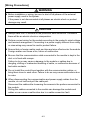
[Wiring Precautions]
WARNING
z Before installation or wiring, be sure to shut off all phases of the external
power supply used in the system.
If the power is not disconnected at all phases an electric shock or product
damage may result.
CAUTION
z Always earth the FG terminal to the protective earth conductor. Otherwise
there will be an electric shock or misoperation.
z Perform correct wiring for the module according to the product’s rated voltage
and terminal arrangement. Connecting to a power supply different from rating
or miss-wiring may cause fire and/or product failure.
z Ensure that no foreign matter such as chips and wire-offcuts enter the module.
Foreign matter can cause a fire, failure or malfunction.
z Be sure that the communication cable connected to the module is kept in the
duct or is fixed with cramps.
Failure to do so may cause a damage to the module or cables due to
dangling, shifting or inadvertent handling of cable, or malfunction because of
bad cable contacts.
z Do not install the control lines together with the communication cables, or
bring them close to each other. Failure to do so may cause malfunctions due
to noise.
z When disconnecting the communication and power supply cables from the
module, do not hold and pull the cable part.
Disconnect the cables after loosening the screws in the portions connected to
the module.
Pulling the cables connected to the module can damage the module and
cables or can cause a malfunction due to a cable connection fault.
A-3
[Starting and Maintenance Precautions]
CAUTION
z Do not disassemble or modify the modules.
Doing so could cause failure, erroneous operation, injury, or fire.
z Be sure to shut down all the phases of the externally supplied power used in
the system before cleaning the module, retightening the module fixing screws,
and attaching/removing the module.
Not doing so can cause the module to fail or malfunction.
z Do not install/remove the terminal block more than 50 times after the first use
of the product. (IEC 61131-2 compliant)
z Before handling the module, make sure to touch a grounded metal object to
discharge the static electricity from the human body.
Failure to do say cause a failure or malfunctions of the module.
[Disposal Precautions]
CAUTION
z When disposing of this product, treat it as industrial waste.
A-4
CONDITIONS OF USE FOR THE PRODUCT
(1) Mitsubishi programmable controller ("the PRODUCT") shall be used in
conditions;
i) where any problem, fault or failure occurring in the PRODUCT, if any,
shall not lead to any major or serious accident; and
ii) where the backup and fail-safe function are systematically or
automatically provided outside of the PRODUCT for the case of any
problem, fault or failure occurring in the PRODUCT.
(2) The PRODUCT has been designed and manufactured for the purpose of
being used in general industries.
MITSUBISHI SHALL HAVE NO RESPONSIBILITY OR LIABILITY
(INCLUDING, BUT NOT LIMITED TO ANY AND ALL RESPONSIBILITY
OR LIABILITY BASED ON CONTRACT, WARRANTY, TORT, PRODUCT
LIABILITY) FOR ANY INJURY OR DEATH TO PERSONS OR LOSS OR
DAMAGE TO PROPERTY CAUSED BY the PRODUCT THAT ARE
OPERATED OR USED IN APPLICATION NOT INTENDED OR
EXCLUDED BY INSTRUCTIONS, PRECAUTIONS, OR WARNING
CONTAINED IN MITSUBISHI'S USER, INSTRUCTION AND/OR SAFETY
MANUALS, TECHNICAL BULLETINS AND GUIDELINES FOR the
PRODUCT.
("Prohibited Application")
Prohibited Applications include, but not limited to, the use of the PRODUCT
in;
• Nuclear Power Plants and any other power plants operated by Power
companies, and/or any other cases in which the public could be
affected if any problem or fault occurs in the PRODUCT.
• Railway companies or Public service purposes, and/or any other cases
in which establishment of a special quality assurance system is
required by the Purchaser or End User.
• Aircraft or Aerospace, Medical applications, Train equipment, transport
equipment such as Elevator and Escalator, Incineration and Fuel
devices, Vehicles, Manned transportation, Equipment for Recreation
and Amusement, and Safety devices, handling of Nuclear or
Hazardous Materials or Chemicals, Mining and Drilling, and/or other
applications where there is a significant risk of injury to the public or
property.
A-5
Notwithstanding the above, restrictions Mitsubishi may in its sole discretion,
authorize use of the PRODUCT in one or more of the Prohibited
Applications, provided that the usage of the PRODUCT is limited only for
the specific applications agreed to by Mitsubishi and provided further that
no special quality assurance or fail-safe, redundant or other safety features
which exceed the general specifications of the PRODUCTs are required.
For details, please contact the Mitsubishi representative in your region.
A-6
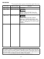
REVISIONS
* The manual number is given on the bottom right of the cover.
Print Date
*Manual Number
Revision
Oct., 2006
IB(NA)-0800346-A First edition
Dec., 2006
IB(NA)-0800346-B
Correction
SAFETY PRECAUTIONS, About the
Manual, Section 2.2, 2.3, 3.1, 3.2, 4.2.1
Dec., 2011
IB(NA)-0800346-C
Correction
SAFETY PRECAUTIONS, ABOUT
MANUALS, COMPLIANCE WITH THE
EMC AND LOW VOLTAGE DIRECTIVES,
Chapter 1, Section 2.3, 3.1, 3.4, 4.1, 4.2.1,
Chapter 6
This manual confers no industrial property rights or any rights of any other kind,
nor does it confer any patent licenses. Mitsubishi Electric Corporation cannot be
held responsible for any problems involving industrial property rights which may
occur as a result of using the contents noted in this manual.
© 2006 MITSUBISHI ELECTRIC CORPORATION
A-7
CONTENTS
1. OVERVIEW .................................................................................................... 1
1.1 Features .................................................................................................. 1
2. SYSTEM CONFIGURATION ......................................................................... 3
2.1 Total configuration ................................................................................... 3
2.2 Applicable system .................................................................................... 4
2.3 Cautions on system configuration ........................................................... 5
3. SPECIFICATION ......................................................................................... 12
3.1 General specifications ........................................................................... 12
3.2 Performance specifications ................................................................... 14
3.3 Specifications of connection cable ........................................................ 17
3.4 Maximum transmission distance ........................................................... 18
4. PROCEDURE UP TO START OF DATA LINK ............................................ 19
4.1 Procedure up to start of data link ........................................................... 19
4.2 Mounting and installation ....................................................................... 20
4.2.1 Cautions on handling .................................................................... 20
4.2.2 Installation environment ................................................................ 23
4.3 Names and settings of parts .................................................................. 24
4.4 Connection of module through CC-Link dedicated cable ...................... 28
4.5 Check for state of connection (line test) ................................................ 29
5. TROUBLESHOOTING ................................................................................. 32
6. EXTERNAL DIMENSIONS .......................................................................... 36
A-8
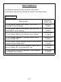
ABOUT MANUALS
The following manuals are also related to this product.
In necessary, order them by quoting the details in the tables below.
Related Manuals
Manual No.
(Model code)
Manual name
CC-Link System Master/Local Module Type AJ61BT11/
A1SJ61BT11 User’s Manual
IB-66721
(13J872)
CC-Link System Master/Local Module Type AJ61QBT11/
A1SJ61QBT11 User’s Manual
IB-66722
(13J873)
CC-Link System Master/Local Module User’s Manual
SH-080394E
(13JR64)
CC-Link System Repeater (T-junction) Module User's
Manual AJ65SBT-RPT
IB-0800078
(13JQ81)
CC-Link System Optical Repeater Module User's Manual
AJ65SBT-RPS/AJ65SBT-RPG
IB-0800089
(13JQ85)
CC-Link System Space Optical Repeater Module User's
Manual AJ65BT-RPI-10A/AJ65BT-RPI-10B
IB-0800090
(13JQ86)
CC-Link System Low Profile Waterproof Type Repeater
Hub Module User’s Manual
IB-0800288
(13JP55)
A-9
COMPlLIANCE WITH EMC AND LOW VOLTAGE DIRECTIVES
(1) Method of ensuring compliance
To ensure that Mitsubishi programmable controllers maintain EMC and Low
Voltage Directives when incorporated into other machinery or equipment,
certain measures may be necessary. Please refer to one of the following
manuals.
• User's manual for the CPU module or head module used
• Safety Guidelines
(this manual is included with the CPU module, base unit, or head module)
The CE mark on the side of the programmable controller indicates
compliance with EMC and Low Voltage Directives.
(2) Additional measures
To ensure that this product maintains EMC and Low Voltage Directives,
please refer to one of the manuals listed under (1).
A-10
Abbreviated names, generic names and terms
Abbreviated names,
generic names and terms
Description
AJ-65BTS-RPH
Abbreviation of AJ65BTS-RPH type CC-Link system spring clamp
terminal Block type Repeater hub module.
AJ65FBTA-RPH
Abbreviation of AJ65FBTA-RPH type CC-Link system low profile
waterproof type repeater hub module.
AJ65SBT-RPT
Abbreviation of AJ65SBT-RPT type CC-Link system repeater (Tjunction) module.
AJ65SBT-RPS/RPG
Abbreviation of AJ65SBT-RPS/AJ65SBT-RPG type CC-Link
system optical repeater module.
AJ65BT-RPI-10A/10B
Abbreviation of AJ65BT-RPI-10A/AJ65BT-RPI-10B type CC-Link
system space optical repeater module.
AJ65SBT-CLB
Abbreviation of AJ65SBT-CLB CC-Link - CC-Link/LT bridge
module.
Segment
System between terminating resistors connected to each other
through cross-over cables.The conventional CC-Link system can be
said to be configured with one segment.
Master station
Station to control the data link system. One station is required for
each system.
Local station
Station which has a sequencer CPU and can communicate with the
master station and the other local stations.
Remote I/O station
Remote station processing only information in unit of bit.
(AJ65BTB1-16D, AJ65SBTB1-16D, etc.)
Remote device station
Remote station processing only information in unit of bit and in unit
of word. (AJ65BT-64AD, AJ65BT-64DAV, AJ65BT-64DAI, etc.)
Remote station
Generic name of remote I/O station and remote device station.
Controlled by the master station.
Intelligent device station
Station allowing transient transmission such as AJ65BT-R2.
(Including local stations)
Repeater
Module for expanding the CC-Link system by connecting the
segments to each other.
Standby master station
Backup station which inherits data link control when the master
station comes off parallel due to error.
Slave station
Generic term of remote I/O station, remote device station, local
station, intelligent device station, and standby master station.
Master local module
Generic name of QJ61BT11N, QJ61BT11, AJ61BT11,
A1SJ61BT11, AJ61QBT11 and A1SJ61QBT11.
Master module
Generic term for modules that can be used as the master station.
Local module
Generic term for modules that can be used as the local station.
A-11
Abbreviated names,
generic names and terms
Description
Intelligent device module Module allowing transient transmission such as AJ65BT-R2.
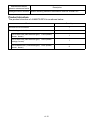
Product structure
The product structure of AJ65BTS-RPH is as shown below.
Product name
Quantity
AJ65FBTA-RPH module
1
Terminating resistor kit
1
For a trunk line (Bar terminal type): 110Ω (brown,
brown, brown)
1
For a trunk line (Bar terminal type): 130Ω (brown,
orange, brown)
1
For a branch line (Y terminal type): 110Ω (brown,
brown, brown)
8
A-12
1. OVERVIEW
This user's manual describes the specifications, names of parts, and settings
of the AJ65BTS-RPH CC-Link system spring clamp terminal block type
repeater hub module (hereafter abbreviated as AJ65BTS-RPH) used in the
CC-Link system.
1.1 Features
The AJ65BTS-RPH is the module designed for improving flexibility in
cable wiring of the CC-Link system.
Using the AJ65BTS-RPH allows the extension of the transmission
distance and star-topology wiring (with 8 branch lines) in the CC-Link
system.
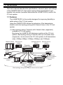
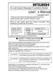
(1) Star-topology wiring (T-branch) with 8 branch lines (segments)
available in CC-Link system
By placing the AJ65BTS-RPH between modules of the CC-Link
system, star-topology wiring (T-branch) with up to 8 branch lines
(segments) can be used in the CC-Link system of all transmission
rates (10Mbps, 5Mbps, 2.5Mbps, 625kbps, and 156kbps).
Master station
Intelligent device Remote device
station
station
Remote I/O
station
Repeater
(AJ65BTS-RPH)
Remote I/O
station
Remote
device station
Intelligent device
station
Remote device
station
Local station
IN
OUT
Repeater
Repeater (AJ65BTS-RPH)
Remote I/O
station (AJ65SBT-RPT)
Star-topology wiring with 8 branch lines can be used!!
1
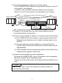
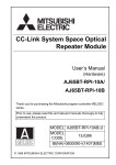
(2) Extended transmission distance in CC-Link system
Use of AJ65BTS-RPH enables the transmission distance of the CCLink system to be extended.
In addition, use of multiple modules enables the transmission
distance of the CC-Link system to be extended up to 2 stages.
Extended to 3.6km (11811.02ft.) max !!*1
Remote
station
Master station
Remote I/O
station
Repeater (AJ65BTS-RPH)
*2
*2
1st stage
2nd stage
*1 Max. transmission distance at a transmission speed of 156kbps.
*2 Though it is not shown here, the other remote stations can be
connected between the repeaters.
(3) Energy saving realized by adoption of a spring clamp terminal block
(a) The AJ65BTS-RPH has adopted a spring clamp terminal block.
Because screw tightening is not needed, working steps can be
reduced.
(b) The terminal block can be installed to or removed from the
module, which reduces the maintenance cost and improves the
maintainability.
(c) All the operation and wiring parts are placed on the module front,
allowing easier operation and wiring.
(4) Improved maintenability by system separation
By using the AJ65BTS-RPH, any of the systems can be separated
and error location can be identified quickly.
This prevents the whole system from being seriously affected by an
error.
POINT
Branch lines with no error can send/receive data normally, not
influenced by each other.
2
2. SYSTEM CONFIGURATION
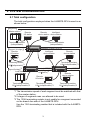
2.1 Total configuration
The total configuration employed when the AJ65BTS-RPH is used is as
shown below.
Segment
Master station
*1
Remote
I/O station
Remote
Intelligent
device station device station
Terminating resistor
(indispensable)
Segment (1st stage)
Remote
I/O station
Terminating resistor
(indispensable)
Repeater (AJ65BTS-RPH)
Intelligent
device station
Terminating resistor,
110 (indispensable)*3
Terminating rresistor,
110 (indispensable)*3
*2
Segment (2nd stage)
Local station
Repeater (AJ65BTS-RPH)
Terminating resistor,
110 (built-in)*3
Remote
I/O station
Terminating resistor,
110 (indispensable)*3
Remote
device station
Terminating resistor,
110 (indispensable)*3
Repeater (AJ65BTS-RPH)
Remote
device station
Terminating resistor,
110 (indispensable)*3
*1 The transmission speed of each segment must be matched with that
of the master station.
*2 2 stages of segments max. are allowed to be used.
*3 The 130Ω terminating resistor is not usable for a segment connected
on the branch line side of the AJ65BTS-RPH.
Use the 110Ω terminating resistor that is included with the AJ65BTSRPH.
3
2.2 Applicable system
This section describes usable modules and cables.
(1) Modules connectable on the branch line side
The types of the modules connectable on the branch line side of the
AJ65BTS-RPH are shown below.
Table 2.1 Modules connectable on the branch line side
Category
Module types
Remote I/O station
Slave station
Remote device station
Intelligent device station
Local station
AJ65BTS-RPH
AJ65FBTA-RPH
Repeater
AJ65SBT-RPT
AJ65SBT-RPS/RPG
AJ65BT-RPI-10A/10B
Bridge
AJ65SBT-CLB
(2) Applicable communication cables
The communication cables connectable to the AJ65BTS-RPH are
shown below.
Table 2.2 Applicable communication cables
Connector
name
Trunk line side
Branch line side
Applicable cable
CC-Link version
Name
Ver.1.00
CC-Link dedicated
high-performance cable
Ver.1.10
CC-Link dedicated cable
Ver.1.00
CC-Link dedicated cable
Ver.1.10
CC-Link dedicated cable
Terminal
resistance
130Ω
CC-Link dedicated cable
110Ω
POINT
The master station and stand by master station can not be connected
to the branch line side.
4
2.3 Cautions on system configuration
(1) Conditions of usable master module
When the AJ61BT11, A1SJ61BT11, AJ61QBT11 and A1SJ61QBT11
modules are used, those of the functional version B or later must be
employed. Use the master module bearing the version 9707 B or
later in the DATE column of the name plate as shown in the figure
below.
When the QJ61BT11N, QJ61BT11 module are used, any module
can be used irrespective of the version.
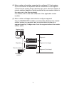
(a) Rating plate of AJ61BT11 or AJ61QBT11
PROGRAMMABLE CONTROLLER
DATE
yymm
B
Year and month of manufacture
(Use a master module of
9707 or later.)
Function version
Conformed standard
MADE IN JAPAN
BD992C077H01
(b) Rating plate of A1SJ61BT11 or A1SJ61QBT11
Year and month of manufacture
(Use a master module of
9707 or later.)
Function version
MODEL
Conformed standard
POWER
DATE
yymm B
MADE IN JAPAN
BD992C077H01
5
(2) Max. number of modules connected to configure CC-Link system
Up to 64 modules of repeaters can be connected in one segment.
In the CC-Link system where repeaters are used, also the number of
remote stations capable of being controlled by one master station is
the same as in the other systems.
For details, refer to the User’s Manual of the applicable master
module.
(3) Max. number of stages connected to configure segment
Use of AJ65BTS-RPH enables communication between the master
station located in a segment and a remote station located in a
segment apart by 2 stages max. from the segment where the master
station exists.
Master station
Terminating
resistor
Segment
Segment (1st stage)
Repeater
Remote station
Segment (2nd stage)
Terminating
resistor
6
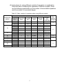
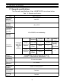
(4) Instructions for using different models of repeaters in combination
Note that when combining the repeaters of different models, there
are the following restrictions on the number of connectable repeaters
and the number of connected stages.
Table 2.3 Max. number of repeaters when using different models
Max. number of repeaters
Combination
AJ65BTS
AJ65FBTA
AJ65SBT AJ65SBT AJ65SBT
pattern
-RPH
-RPH
-RPT
-RPS
-RPG
1)
2)
3)
4)
5)
6)
7)
8)
9)
1
—
1
1
—
—
1
—
—
—
—
—
—
—
1
—
1
—
—
1
1
—
1
—
—
—
—
—
—
1
2
2
—
—
—
—
—
—
2
2
2
—
—
—
—
—
—
2(1set)
—
2(1set)
—
—
—
4(2set)
—
—
2(1set)
2(1set)
—
—
7
—
—
2(1set)
—
2(1set)
—
—
—
2(1set)
—
2(1set)
—
2(1set)
—
Max.
AJ65BT
number
-RPI
of stages
-10A/10B
—
3
—
—
—
—
2
—
2(1set)
2(1set)
—
4
—
3
2(1set)
—
2(1set)
2
2(1set)
—
POINT
• For the CC-Link system, up to 2 repeater types can be used in
combination.
Using 3 models or more is not allowed.
• When repeaters are connected in the same segment by link wiring, up to
64 modules can be connected.
For details, refer to the user’s manual of the master module used.
• Ex.) A CC-Link system with combination pattern 3) is built
Master station
Segment
AJ65BTS-RPH
Up to 64 modules can be
connected in a segment.
AJ65BT-RPI
Segment
1st stage
Segment
2nd stage
AJ65BT-RPI
Remote station
Segment
3rd stage
For combination pattern 3),
4 (2 sets) or more AJ65BT-RPIs
are not connectable.
8
(a) Combination pattern 1)
(c) Combination pattern 3)
Master station
Master station
Segment
Segment
AJ65BTS-RPH or
AJ65FBTA-RPH
One module
AJ65BTS-RPH or
AJ65FBTA-RPH
One module
Segment
1st stage
Segment
1st stage
AJ65BTS-RPH or
AJ65FBTA-RPH
Two module
(one set)
IN
AJ65BT-RPI
Two modules
(one set)
OUT
Segment
2nd stage
IN
Segment
2nd stage
OUT
Remote station
Segment
3rd stage
Remote station
(b) Combination pattern 2)
(d) Combination pattern 4)
Master station
Master station
Segment
Segment
AJ65BTS-RPH or
AJ65FBTA-RPH
One module
IN
OUT
IN
OUT
AJ65SBT-RPT
Up to two modules
Segment
1st stage
AJ65SBT-RPS or
AJ65SBT-RPG
Two modules
(one set)
Segment
1st stage
Segment
2nd stage
Segment
2nd stage
AJ65SBT-RPS
Four modules
(two sets)
or
Two modules
(one set)
Remote station
Segment
3rd stage
Segment
4th stage
Remote station
9
(e) Combination pattern 5)
(g) Combination pattern 7)
Master station
Master station
Segment
Segment
IN
OUT
AJ65SBT-RPT
Up to two modules
AJ65SBT-RPS
Two modules
(one set)
Segment
1st stage
IN
OUT
Segment
1st stage
Segment
2nd stage
AJ65SBT-RPG
Two modules
(one set)
AJ65SBT-RPG
Two modules
(one set)
Segment
2nd stage
Segment
3rd stage
Remote station
Remote station
(f) Combination pattern 6)
(h) Combination pattern 8)
Master station
Master station
Segment
Segment
IN
OUT
IN
OUT
AJ65SBT-RPT
Up to two modules
AJ65SBT-RPS or
AJ65SBT-RPG
Two modules
(one set)
Segment
1st stage
Segment
1st stage
Segment
2nd stage
AJ65BT-RPI
Two modules
(one set)
AJ65BT-RPI
Two modules
(one set)
Segment
3rd stage
Segment
2nd stage
Remote station
Remote station
10
(i) Combination pattern 9)
Master station
Segment
AJ65BTS-RPH
One module
Segment
1st stage
AJ65FBTA-RPH
One module
Segment
2nd stage
Remote station
11
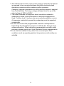
3. SPECIFICATION
3.1 General specifications
The General specifications of the AJ65BTS-RPH are shown below.
Table 3.1 General specifications
Item
Specifications
Operating
ambient
temperature
0 to 55°C
Storage
ambient
temperature
-20 to 75°C
Operating
ambient
humidity
10 to 90%RH, non-condensing
Storage
ambient
humidity
Vibration
resistance
Shock
resistance
Operating
atmosphere
Compliant
with JIS B
3502 and
IEC
61131-2
Under
intermittent
vibration
Under
continuous
vibration
Frequency
Constant
acceleration
Half
amplitude
Sweep
count
5 to 8.4Hz
—
3.5mm
8.4 to
150Hz
9.8m/s2
—
10 times
each in
X, Y, Z
directions
5 to 8.4Hz
—
1.75mm
8.4 to
150Hz
2
4.9m/s
—
Compliant with JIS B 3502 and IEC 61131-2
(147m/s2, 3 times each in 3 directions X, Y, Z)
No corrosive gases
Operating
altitude*3
0 to 2000m
Installation
location
Inside a control panel*4
Overvoltage
category*1
II or less
Pollution
degree*2
2 or less
12
—
*1 This indicates the section of the power supply to which the equipment
is assumed to be connected between the public electrical power
distribution network and the machinery within premises.
Category II applies to equipment for which electrical power is supplied
from fixed facilities. The surge voltage withstand level for up to the
rated voltage of 300V is 2500V.
*2 This index indicates the degree to which conductive material is
generated in terms of the environment in which the equipment is
used. Pollution level 2 is when only non-conductive pollution occurs.
A temporary conductivity caused by condensing must be expected
occasionally.
*3 Do not use or store the programmable controller under pressure
higher than the atmospheric pressure of altitude 0m. Doing so may
cause malfunction. When using the programmable controller under
pressure, please consult your local Mitsubishi Electric representative.
*4 It can also be installed to any other than a control panel if the
conditions such as operating ambient temperature and humidity are
satisfied.
13
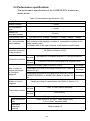
3.2 Performance specifications
The performance specifications of the AJ65BTS-RPH module are
shown below.
Table 3.2 Performance specifications (1/2)
Item
Specifications
Station number
- (none)
CC-Link station
type
- (none)
Number of
occupied stations
0 (none)
Transmission rate
No. of connectable
slave stations
Can select from 156kbps / 625kbps / 2.5Mbps / 5Mbps / 10Mbps
The total number of modules connected to a trunk line and branch line
shall conform to the maximum number of connectable modules of the
master module used.
For details, refer to the user’s manual of the master modules used.
Max. No. of
modules connected
to the trunk line
Connection position
Max. number of
stages connected
to configure
segment
Max. transmission
distance of each
segment
Terminating resistor
Terminal block
Applicable cable
size
64 (Refer to Section 2.3(2))
Trunk
line side
No restriction (compliant with the CC-Link specifications)
Branch
line side
Connect to the end of the branch line (segment end)
AJ65BTS-RPH only (Refer to Section 2.3(3))
2nd stage
Combination of AJ65BTS-RPH and AJ65SBT-RPT (Refer to
Section 2.3 (4))
3rd stage
Combination of AJ65BTS-RPH and one of AJ65FBTA-RPH,
AJ65SBT-RPS/RPG, or AJ65BT-RPI (Refer to Section 2.3
(4))
2nd stage
Varies according to transmission rate (Refer to Section 3.4.).
Trunk
line side
110Ω, or 130Ω can be selected.
Branch
line side
110Ω (built-in)
Spring clamp terminal block
AWG #24 to 12, φ0.5 to 1.78mm single cable,
0.2 to 2.5mm2 stranded cable
Applicable
solderless
terminal
Refer to table 3.3
14
Table 3.2 Performance specifications (2/2)
Item
Specifications
Mounting
orientation
No restriction (mountable in six orientations)
Module installation
screw
Power
supply
Voltage
M4 mounting screw
24V DC external power supply (20.4 to 26.4V, ripple within ±5%)
Current
Noise durability
Maximum voltage
Insulation
resistance
0.36A (TYP. 24V DC)
Simulator noise of 500 Vp-p, obtained by a noise simulator using noise
width of 1 s and noise frequency of 25 to 60 Hz
500V AC for 1 minute between all DC external terminals and ground
10M
or higher, measured with a 500V DC insulation resistance tester
Protection of
degree
IP2X
External
dimensions
197.4mm (7.77in.) (W) × 65mm (2.56in.) (H) × 65.8mm (2.59in.) (D)
Weight
0.37kg
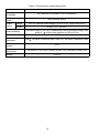
15
Table 3.3 Applicable solderless terminals (bar terminals) and crimp tools
Product name
Bar-type
solderless
terminal
Model name
FA-TVC125T9
Tool for bartype solderless FA-NH65A
terminals
Bar-type
solderless
terminal
Maker
Mitsubishi Electric
Engineering Co., Ltd.
Remark
For CC-Link dedicated cables
(0.3 to 1.65mm2)
TE0.5-10
For CC-Link dedicated cables
(0.3 to 0.5mm2)
TE0.75-10
For power supply cables
(0.75mm2)
TE1.0-10
TE1.5-10
NICHIFU TERMINAL
MFG. Co., Ltd.
For power supply cables
(1.0mm2)
For power supply cables
(1.5mm2)
For power supply cables
(2.5mm2)*2
TE2.5-12
Tool for bartype solderless NH-79
terminals
Bar-type
solderless
terminal
AI0.5-10WH
For CC-Link dedicated cables
(0.5mm2)
AI0.75-10GY
For power supply cables
(0.75mm2)
AI1-10RD
For power supply cables
(1.0mm2)
AI1.5-10BK
PHOENIX CONTACT
For power supply cables
(1.5mm2)
For power supply cables
(2.5mm2)*2
AI2.5-10BU
CRIMPFOX UD6
Tool for barCRIMPFOX UD6-4
type solderless
CRIMPFOX UD6-6
terminals
CRIMPFOX ZA3
*1
*1
*1: When shielding wires, power supply cables of 2 mm2 (AWG #14) or
FG wires are crimped to bar terminals using the CRIMPFOX UD6-4
or CRIMPFOX UD6-6, bar terminals may not be able to connect to
the terminal block depending on the cross-sectional shape after
crimping.
*2: When power supply cables of 2 mm2 (maximum size of applicable
cables) or FG wires are crimped to bar terminals of 2.5 mm2, bar
terminals may not be able to connect to the terminal block.
16
3.3 Specifications of connection cable
Use the CC-Link dedicated cable for the CC-Link system. If a cable
other than the CC-Link dedicated cable is used, the performance of the
CC-Link system cannot be guaranteed.
For the CC-Link cable specifications and any other inquiries, refer to the
following:
CC-Link Partner Association website: http://www.cc-link.org/
REMARK
For details, refer to the CC-Link cable wiring manual issued by the CC-Link
Partner Association.
17
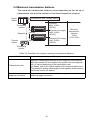
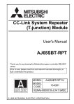
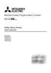
3.4 Maximum transmission distance
The maximum transmission distance varies depending on the set-up of
transmission rate and the number of connected segments (stages).
Transmission rate:156kbps setting
Master
station
Segment
Max. 1200m
(3937ft.)
Terminating
resistor
Segment (1st stage)
Max. 1200m
(3937ft.)
Repeater
Segment (2nd stage)
Max. 1200m
(3937ft.)
Remote
station
Maximum
transmission
distance
3.6km
(11811.02ft.)
Terminating
resistor
Table 3.4 Conditions for change in maximum transmission distance
Condition
Description
Transmission rate
Maximum transmission distance in each segment is the same as
that of the normal CC-Link system (the system with one segment
only). It varies depending on the transmission rate.
For details, refer to the user’s manual of the master module used.
(The station-to-station cable length for the repeater is the same as
that for the remote I/O station.)
No. of stages for
segment connection
Maximum transmission distance for one segment is added for each
additional stage connection.
18
4. PROCEDURE UP TO START OF DATA LINK
4.1 Procedure up to start of data link
The procedure ranging from the installation of the AJ65BTS-RPH
module to the start of data link is described below.
Start
Install the AJ65BTS-RPH module.
Refer to Section 4.2.
Set the switches of the module.
Refer to Section 4.3.
Connect the modules using CC-Link
dedicated cables.
Refer to Section 4.4.
Check for the connection conditions
of the modules (line test).
Refer to Section 4.5.
Start the system.
Refer to the User’s Manual
of the applicable master module.
Completion
POINT
The procedure described here is for the AJ65BTS-RPH module only.
In order for you to understand the procedure of the entire CC-Link
system, refer to the User’s Manual of the applicable master module.
19
4.2 Mounting and installation
4.2.1 Cautions on handling
Cautions on handling the AJ65BTS-RPH module are described
below.
(1) Tighten screws (such as a module fixing screw) within the tightening
torque range specified in the table below.
Do not over-tighten these screws. The screws and module case may be
damaged.
Table 4.1 Specified torque range for each screw
Screw location
Specified torque range
Module installation screw (M4 screws)
Terminal block fixing screw
0.78 to 1.08N•m
0.4 to 0.5N•m (conforming to IEC 60999)
(2) When a DIN rail is used, install it taking care with the following.
(a) Applicable DIN rail type (conforming to IEC 60715)
TH35-7.5Fe
TH35-7.5Al
(b) Intervals of DIN rail mounting screws
Mount the DIN rail by fixing it with mounting screws at intervals of 200
mm (7.87inch) or shorter.
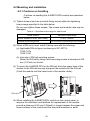
(3) To mount the AJ65BTS-RPH to the DIN rail, hitch the upper hook of the
module to the DIN rail securely and push the module into the DIN rail.
(Push the module until the lower hook of the module clicks.)
DIN rail
(4) When installing the AJ65BTS-RPH module on the control panel, to
improve the ventilation and facilitate the replacement of the module,
provide a distance of 60 mm (2.36inch) or longer between the upper and
lower surfaces of the module and the structural members or parts.
20
(5) Install the AJ65BTS-RPH module on a flat smooth surface.
If there are irregularities on the installation surface, undue force may be
applied to the printed circuit boards, and the boards may be damaged.
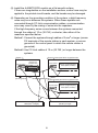
(6) Depending on the grounding condition of the system, a high-frequency
noise may occur between the systems. When these systems are
connected through CC-Link communication cables, a communication
error may occur by the mixing of noise into the repeaters.
If the high-frequency noise occurs between the systems connected
through the cables of 10 m (32.79ft.) or shorter, take either of the
measures specified below.
Method1:Connect the systems through cables of 2 mm2 or larger (across
FG terminals of the remote station in each system, or across
grounds of the control panel to which the remote station is
grounded).
Method2:Use CC-Link cables of 10 m (32.79ft.) or longer between the
systems.
System 1
Remote station
System 2 Control panel which may produce noise
Repeater Hub
(AJ65BTS-RPH)
Remote station
(To the ground)
Source of high-frequency
noise (Serov, inverter)
System 3 Control panel which may produce noise
Remote station
Source of high-frequency
noise (Serov, inverter)
Method 2: Use the cables of 10m
(32.79ft.) or longer.
Method 1: Use the stronger ground
cable (2mm2 or larger).
21
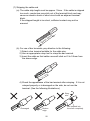
(7) Stripping the cable end
(a) The cable strip length must be approx. 10mm. If the cable is stripped
too much, conductors may stick out of the terminal block and may
cause an electric shock or short circuit with an adjacent terminal
block.
If the stripped length is too short, sufficient contact may not be
ensured.
ble
Ca
m
0m
.1
ox
pr
Ap
(b) For use of bar terminals, pay attention to the following:
1) Select a bar terminal suitable for the cable size.
2) Use an appropriate crimp tool to crimp the bar terminal.
3) Insert the cable so that cable cores will stick out 0 to 0.5mm from
the sleeve edge.
ble
ell
Ca
Sh
e
ev
Sle
0
to
mm
0.5
4) Check the appearance of the bar terminal after crimping. If it is not
crimped properly or is damaged on the side, do not use the
terminal. (See the following illustrations.)
Stray
wire
Damaged
Broken
edge
22
Not inserted into
the shell completely
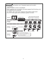
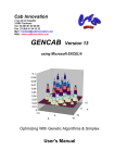
(8) Connecting the cable to the spring clamp terminal block
(a) Connecting the cable
While pressing the open/close button with a flat-head screwdriver,
insert the cable into the insertion hole.
1) For use of bar terminals, the cable can be inserted without pressing
the open/close button.
Insertion hole
Open/close
button
(b) Disconnecting the cable
While fully pressing the open/close button with the flat-head
screwdriver, pull out the cable.
4.2.2 Installation environment
For installation environment, refer to Section 3.1.
23
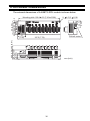
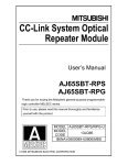
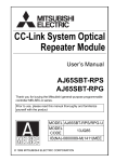
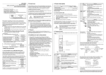
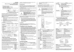
4.3 Names and settings of parts
The names of parts of the AJ65BTS-RPH module, indication statuses of
LEDs, and settings of switches are described below.
1)
2)
6)
7)
6)
3)
4)
5)
24
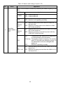
Table 4.2 Names and settings of parts (1/3)
No.
Name
Application
Check for the module condition by observing the state of lighting of the
LED.
LED Name
1)
Operation
status display
LED
Application
POWER
ON : Power supply on
OFF : Power supply off
RUN
ON : Module is operating normally
OFF : Module is not operating normally
SD
LINK IN/
OUT
ON : Data are being sent to the LINK IN or LINK OUT of
the trunk line
OFF : Data are not being sent to the LINK IN or LINK
OUT of the trunk line
RD
LINK IN/
OUT
ON : Data are being received from the LINK IN or LINK
OUT of the trunk line
OFF : Data are not being received from the LINK IN or
LINK OUT of the trunk line
ON
ERR.
: Transmission rate setting out-of-range error
or communication error occurred
Flickering : Terminating resistor is missing. The module
and CC-Link cables are affected by noise. Or
the transmission rate was changed after
power up.
OFF
: Module is operating normally
RD
LINK 1 to 8
ON : Data are being received from the LINK1 to 8 of the
branch line.
OFF : Data are not being received from the LINK1 to 8 of
the branch line.
25
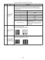
Table 4.2 Names and settings of parts (2/3)
No.
Name
Application
Set the transmission rate of the module (set to 0 at the time of delivery).
Ensure to set the transmission rate at a speed specified below.
Transmission rate of the trunk line side is identical with that of the
branch line side.
2)
Transmission
rate setting
switch
Setting value
Transmission rate (bps)
0
156k
1
625k
2
2.5M
3
5M
4
10M
Other than 0 to 4
Cannot be set.
If set to other than 0 to 4, the ERR.
LED is turned on and data are not
transferred.
Connects the module power supply (24V DC) and the ground cable
(FG: Functional Ground).
Terminals are assigned as follows:
3)
Power terminal
block
+24V +24V
24G 24G
NC NC
FG
FG
FG
FG
Connects the transmission lines on the trunk line side (LINK IN/OUT).
Terminals are assigned as follows:
4)
Communication
terminal block
(Trunk line side)
DA DA
DB DB
DG DG
SLD SLD
26
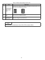
Table 4.2 Names and settings of parts (3/3)
No.
Name
Application
Connects the transmission lines on the branch line side (LINK 1 to 8).
Terminals are assigned as follows:
5)
Communication
terminal block
(Branch line
side)
6)
Module fixing
hole
Screw hole for fixing the module.
7)
Terminal block
fixing screw
Screw for fixing the terminal block.
DA
DB
DG
SLD
POINT
Set the same transmission rate as that of the master station.
27
4.4 Connection of module through CC-Link dedicated cable
The method of connecting the AJ65BTS-RPH module to the CC-Link
system through the CC-Link dedicated cable is shown below.
Master station
Remote I/O
station
Intelligent device
station
Repeater
(AJ65BTS-RPH)
(1)
Remote I/O
station
Repeater
(AJ65BTS-RPH)
(2)
(3)
Remote I/O
station
(5)
(4)
For (1) to (5) shown in the above, read the following cautions on
connections.
(1) For the segment connected to the trunk line side of the AJ65BTSRPH, connect a terminating resistor to the module connected at the
end.
Select a type for terminating resistor in accordance with the type of
the connected communication cable.
For details, refer to the manual of the module connected.
(2) Do not connect any terminating resistor to the AJ65BTS-RPH when
the trunk line side is connected to a station that is not located at the
end of the segment.
In addition, connect the shielding wire of the CC-Link dedicated
cable to “SLD” of each module, and ground both ends via “FG” The
interval between SLD and FG is connected in the module in
advance.
(3) Connect the included terminating resistor to the AJ65BTS-RPH
when the trunk line side is connected to a station that is located at
the end of the segment.
Select a type for terminating resistor in accordance with the type of
the connected communication cable.
For details, refer to Section 2.2.
In addition, connect the shielding wire of the CC-Link dedicated
cable to “SLD” of each module, and ground both ends via “FG” The
interval between SLD and FG is connected in the module in
advance.
28
(4) Connect the included 110Ω terminating resistor to the module
located at the end of a segment when the branch line side of the
AJ65BTS-RPH is connected to the segment.
For the connection of terminal resistor, refer to the manual of the
module connected.
(5) For the branch line side of the AJ65BTS-RPH, use the incorporated
110Ω terminating resistor.
In addition, connect the shielding wire of the CC-Link dedicated
cable to “SLD” of each module, and ground both ends via “FG”.
Note that SLD and FG are connected to each other in the module.
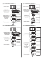
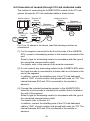
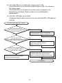
4.5 Check for state of connection (line test)
Connect all modules including the AJ65BTS-RPH module through the
CC-Link dedicated cable. Then, check that the CC-Link system is in the
state capable of performing a data link normally.
Because whether or not a master station can establish a data link with a
particular slave station can be checked by the connection status check
(circuit test), an error module can be identified.
For the connection status check (circuit test), perform the circuit test 1 of
the master module. If an error is detected, perform the circuit test 2 of
the master module.
For the details of circuit tests 1 and 2, refer to the user’s manual of the
master module used.
Perform the test following the steps shown below.
POINT
Perform the circuit test 2 of the master module by selecting the target
stations as described in (1) to (3) below.
(1) In the segment including the master module, select slave stations
in order from the nearest to the master module to the farthest.
(2) In the segment (1st stage), select slave stations in order from the
nearest to the AJ65BTS-RPH to the farthest.
(3) In the segment (2nd stage), select slave stations in order from the
nearest to the AJ65BTS-RPH to the farthest.
29
Start
Confirm that input power supply voltage is
correct, and turn on the external power supply.
Does POWER LED
light up?
NO
Refer to Chapter 5 (1) to perform
troubleshooting.
YES
Does RUN LED
light up?
NO
Refer to Chapter 5 (2) to perform
troubleshooting.
YES
Perform the circuit test 1 of the master module.
Any error detected in the
circuit test 1?
NO
Completion
YES
Perform the circuit test 2 of the master module.
Any error detected in the
circuit test 2?
NO
Completion
YES
1)
30
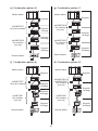
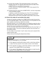
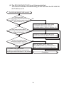
1)
Didn't the ERR. LED
light up or blink?
NO
Refer to Chapter 5 (3) to perform
troubleshooting.
YES
Did the RD LINK IN/OUT LED light up?
NO
Refer to Chapter 5 (4) to perform
troubleshooting.
YES
Did the RD LINK1 to 8 LEDs of
the branch line used in the circuit
test 2 light up?
NO
Refer to Chapter 5 (5) to perform
troubleshooting.
YES
The hardware may have a defect.
Contact your local Mitsubishi representative,
explaining a detailed description of the problem.
31
5. TROUBLESHOOTING
This section describes the measures when a trouble occurred in the
AJ65BTS-RPH.
Perform the troubleshooting indicated in the reference section.
No.*1
Reference
section
Problem
1
The POWER LED is not lit while the module power is ON.
2
The RUN LED is not lit while the module power is ON.
(1) in this chapter
(2) in this chapter
3
The ERR. LED lighted up or blinked.
(3) in this chapter
4
The RD LINK IN/OUT LED does not light up during data link.
(4) in this chapter
5
The RD LINK 1 to 8 LEDs corresponding to the data linking branch
(5) in this chapter
lines do not light up.
*1 If more than one problem occurred simultaneously, perform the
troubleshooting in order of the item numbers.
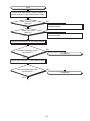
(1) The POWER LED is not lit while the module power is ON
Troubleshooting is shown below for the case that the POWER LED is not
lit while the module power is ON.
The POWER LED does not light up
Was the module power turned on?
YES
Is the power cable connected correctly?
(Refer to Section 4.3)
YES
Is power supply voltage correct?
(Refer to Section 3.2)
YES
NO
Turn on the module power.
NO
Connect the power cable correctly.
(Refer to Section 4.3)
NO
Correct the power supply voltage.
(Refer to Section 3.2)
The hardware may have a defect.
Contact your local Mitsubishi representative,
explaining a detailed description of the problem.
Completion
32
(2) The RUN LED is not lit while the module power is ON.
If the RUN LED is not lit while the module power is ON, turn off and on
the module again.
If the RUN LED is not lit after the module power is reapplied, the
hardware may be faulty. Please contact your local Mitsubishi
representative.
(3) The ERR. LED lights up or blinks.
Troubleshooting is shown below for the case that the ERR. LED lights up
or blinks.
The ERR. LED lights up or blinks.
Is the transmission rate of
AJ65BTS-RPH set in the valid range?
(Refer to Section 4.3)
YES
Is the connection of the
communication cable and terminating resistor
correct? (Refer to Section 4.4)
YES
Is there any noise source
around the AJ65BTS-RPH or
communication cable?
YES
Refer to (4) and (5) in this chapter
to perform troubleshooting.
NO
Correct the transmission rate setting
of AJ65BTS-RPH. (Refer to Section 4.3)
NO
Connect the communication cable and
terminating resistor correctly.
(Refer to Section 4.4)
NO
Move the noise source away from the
AJ65BTS-RPH and communication
cable to a place not influenced by noise.
Completion
33
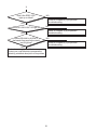
(4) The RD LINK IN/OUT LED is not lit during data link.
This section describes troubleshooting for the case that the RD LINK IN/
OUT LED is not lit.
The RD LINK IN/OUT LED is not lit.
Is the transmission
rate setting identical between
AJ65BTS-RPH and the master station?
(Refer to Section 4.3)
YES
Is the communication cable of
the trunk line side connected correctly?
(Refer to Section 4.4)
YES
Is there any noise source
around the AJ65BTS-RPH or
communication cable?
YES
NO
Correct the transmission rate setting
of AJ65BTS-RPH to the same as
the master station. (Refer to Section 4.3)
NO
Connect the communication cable of the
trunk line side correctly. (Refer to Section 4.4)
NO
Move the noise source away from
the AJ65BTS-RPH and communication
cable to a place not influenced by noise.
The hardware may have a defect.
Contact your local Mitsubishi representative,
explaining a detailed description of the problem.
Completion
34
(5) The RD LINK 1 to 8 LEDs corresponding to the data linking branch lines
are not lit.
This section describes troubleshooting when the RD LINK 1 to 8 LEDs
corresponding to the data linking branch lines are not lit.
RD LINK 1 to 8 LEDs are not lit
Is the transmission
rate setting identical between
AJ65BTS-RPH and the remote station?
(Refer to Section 4.3)
YES
Is the setting of destination
remote station set on the master
station correct?
YES
Is the communication
cable of the branch line side connected
correctly? (Refer to Section 4.4)
YES
Is there any error on
the remote station?
YES
Is there any noise source
around the AJ65BTS-RPH or
communication cable?
YES
NO
Correct the transmission rate setting
of the remote station to the same
as AJ65BTS-RPH. (Refer to Section 4.3)
NO
Correct the setting of the destination
remote station set on the master station.
NO
Connect the communication cable of the branch
line side correctly. (Refer to Section 4.4)
NO
Restore the faulty area referring to the
manual of the remote station.
NO
Move the noise source away from the
AJ65BTS-RPH and communication
cable to a place not influenced by noise.
The hardware may have a defect.
Contact your local Mitsubishi representative,
explaining a detailed description of the problem.
Completion
35
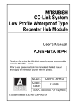
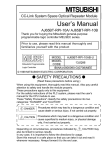
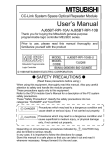
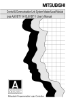
6. EXTERNAL DIMENSIONS
The external dimensions of AJ65BTS-RPH module is shown below.
0.008)
2-
4.5 (2-
0.18)
32.7
(1.29)
0.2 (7.42
37
(1.46)
DIN rail center
197.5 (7.78)
45.5 (1.79) 20.5 (0.81)
28.5 (1.12)
9 (0.35)
65 (2.56)
Mounting pitch 56 0.2
(2.20 0.008)
Mounting pitch 188.4
mm (inch)
36
MEMO
37
WARRANTY
Mitsubishi will not be held liable for damage caused by factors found not to be the cause of
Mitsubishi; machine damage or lost profits caused by faults in the Mitsubishi products; damage,
secondary damage, accident compensation caused by special factors unpredictable by
Mitsubishi; damages to products other than Mitsubishi products; and to other duties.
Country/Region Sales office/Tel
Country/Region Sales office/Tel
U.S.A
Mitsubishi Electric Automation Inc.
500 Corporate Woods Parkway Vernon
Hills, IL 60061, U.S.A.
Tel : +1-847-478-2100
China
Mitsubishi Electric Automation
(China) Ltd.
4/F Zhi Fu Plazz, No.80 Xin Chang Road,
Shanghai 200003, China
Tel : +86-21-6120-0808
Brazil
MELCO-TEC Rep. Com.e Assessoria
Tecnica Ltda.
Rua Correia Dias, 184,
Edificio Paraiso Trade Center-8 andar
Paraiso, Sao Paulo, SP Brazil
Tel : +55-11-5908-8331
Taiwan
Setsuyo Enterprise Co., Ltd.
6F No.105 Wu-Kung 3rd.Rd, Wu-Ku
Hsiang, Taipei Hsine, Taiwan
Tel : +886-2-2299-2499
Korea
Mitsubishi Electric Automation
Korea Co., Ltd.
1480-6, Gayang-dong, Gangseo-ku
Seoul 157-200, Korea
Tel : +82-2-3660-9552
Germany
Mitsubishi Electric Europe B.V. German
Branch
Gothaer Strasse 8 D-40880 Ratingen,
GERMANY
Tel : +49-2102-486-0
U.K
Mitsubishi Electric Europe B.V. UK
Branch
Travellers Lane, Hatfield, Hertfordshire.,
AL10 8XB, U.K.
Tel : +44-1707-276100
Singapore
Mitsubishi Electric Asia Pte, Ltd.
307 Alexandra Road #05-01/02,
Mitsubishi Electric Building,
Singapore 159943
Tel : +65-6470-2480
Italy
Mitsubishi Electric Europe B.V. Italian
Branch
Centro Dir. Colleoni, Pal. Perseo-Ingr.2
Via Paracelso 12, I-20041 Agrate Brianza.,
Milano, Italy
Tel : +39-039-60531
Thailand
Mitsubishi Electric Automation (Thailand)
Co., Ltd.
Bang-Chan Industrial Estate No.111
Moo 4, Serithai Rd, T.Kannayao,
A.Kannayao, Bangkok 10230 Thailand
Tel : +66-2-517-1326
Spain
Mitsubishi Electric Europe B.V. Spanish
Branch
Carretera de Rubi 76-80,
E-08190 Sant Cugat del Valles,
Barcelona, Spain
Tel : +34-93-565-3131
Indonesia
P.T. Autoteknindo Sumber Makmur
Muara Karang Selatan, Block A/Utara
No.1 Kav. No.11 Kawasan Industri
Pergudangan Jakarta - Utara 14440,
P.O.Box 5045 Jakarta, 11050 Indonesia
Tel : +62-21-6630833
France
Mitsubishi Electric Europe B.V. French
Branch
25, Boulevard des Bouvets, F-92741
Nanterre Cedex, France
Tel : +33-1-5568-5568
India
Messung Systems Pvt, Ltd.
Electronic Sadan NO:III Unit No15,
M.I.D.C Bhosari, Pune-411026, India
Tel : +91-20-2712-3130
Australia
Mitsubishi Electric Australia Pty. Ltd.
348 Victoria Road, Rydalmere,
N.S.W 2116, Australia
Tel : +61-2-9684-7777
South Africa Circuit Breaker Industries Ltd.
Private Bag 2016, ZA-1600 Isando,
South Africa
Tel : +27-11-928-2000
HEAD OFFICE : TOKYO BUILDING, 2-7-3 MARUNOUCHI, CHIYODA-KU, TOKYO 100-8310, JAPAN
NAGOYA WORKS : 1-14, YADA-MINAMI 5-CHOME, HIGASHI-KU, NAGOYA, JAPAN
When exported from Japan, this manual does not require application to the Ministry
of Economy, Trade and Industry for service transaction permission.
Specifications subject to change without notice.