1
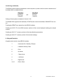
Model 9500
Dissolved Oxygen Meter
Operating Manual
950 050/REV A/04-03
SAFETY
Please read this information carefully prior to installing or using this equipment.
1. The unit described in this manual is designed to be operated only by trained personnel. Any
adjustments, maintenance and repair must be carried out as defined in this manual, by a person
qualified to be aware of the hazards involved.
2. It is essential that both operating and service personnel employ a safe system of work, in addition to
the detailed instructions specified in this manual.
3. References should always be made to the Health & Safety data supplied with any chemicals used.
Generally accepted laboratory procedures for safe handling of chemicals should be employed.
4. If it is suspected that safety protection has been impaired in any way, the unit must be made
inoperative and secured against any intended operation. The fault condition should immediately be
reported to the appropriate servicing authority.
950 050/REV A/04-03
Model 9500
Dissolved Oxygen Meter
Operating Manual
Contents
Section 1
Section 2
Section 3
Section 4
Section 5
Section 6
Section 7
Introduction
Instrument Description
Instrument Specification
1.1
1.2
Installation
Unpacking
Installation
Displays
Keypad
Inputs/Outputs
2.1
2.2
2.3
2.4
2.5
Operation
Good Practice Guidelines
Set Up Parameters
%DO2 Mode
B.O.D.
Status Page
Results Storage & Display
GLP Functions
3.1
3.2
3.3
3.4
3.5
3.6
3.7
Maintenance
General
Probe Care & Maintenance
4.1
4.2
Optional Accessories
Optional Accessories
Spares
5.1
5.2
Interfacing
Analogue
RS232
Keypad Emulation
Printing
Alarm Outputs
6.1
6.2
6.3
6.4
6.5
Troubleshooting
Troubleshooting
7.1
Health & Safety
EC Declaration of Conformity
950 050/REV A/04-03
Model 9500
Dissolved Oxygen Meter
Operating Manual
Section 1
Introduction
1.1 Instrument Description
The 9500 is a fully specified DO2/Temperature meter that includes full support for the B.O.D. 5-day
test protocol. Up to 20 B.O.D. tests, each with up to 10 samples, can be stored. Powerful data logging
capabilities are included, with the ability to store up to 250 DO2 readings either manually, at timed
intervals or alarm events.
1.2 Specification
DO2
Ranges
Resolution
Accuracy
Pressure correction
Salinity correction
0 to 199%./ 0 to 25.0% / 0 to 19.99mg/l
1%./ 0.1% / 0.01mg/l
±2% within 10°C of calibration temperature
Manual
Manual
Temperature
Range
Resolution
Accuracy
-10 to +60°C (14 to 140°F)
0.1°C (1°F)
±0.5°C (±1°F)
ATC Range
Manual Temp. Comp. Range
0 to 60°C (32 to 140°F)
0 to 60°C (32 to 140°F)
Calibration
Automatic
Outputs
Analogue
RS232 serial & IrDA printer interface
Alarm
24 hours, hrs/min/sec or day of month/month/year
leap year corrected (European and American formats)
Calibration reminder interval (1 to 999 hours)
Alarm outputs (open collector and audible)
Security code protected user data
Back lit 1/8 VGA monochrome LCD
English, French, German, Italian, Spanish, Portuguese
9V power supply
210x250x55mm
850g
Clock
GLP
Display
Language option
Power
Size
Weight
1
950 050/REV A/04-03
Section 2
Installation
2.1 Unpacking
Remove the Model 9500 from the packaging and ensure the following items are included:
1.
2.
3.
4.
5.
6.
7.
8.
9.
Model 9500 Dissolved Oxygen Meter
Dissolved Oxygen probe with ATC (522 008)
3 membranes & KCl solution (522 019)
Zero salts (983 030)
Adaptor bush
Electrode holder
Power Supply (as specified at time of ordering the product)
Condensed operating instructions (950 051)
Operating Manual (950 050)
The electrode stand requires minimal assembly (refer to the diagram below)
Any shortages or damage should be reported immediately to the manufacturer or your local
distributor.
2.2 Installation
The Model 9500 is supplied ready to use. Connect the dissolved oxygen probe to the rear panel DIN
socket.
The electrode stand requires minimal assembly (refer to the diagram below).
Fig. 2.2.1 Electrode Holder Assembly
4
1
2
3
2
950 050/REV A/04-03
Preparation for use
The probe is delivered with the membrane module detached. Prior to use the membrane module
must be fitted to the probe body.
A protective cap is also supplied. This should be fitted to the probe when not in use. The sponge
contained within the cap should be wetted with deionised water prior to fitting. This covers the
membrane and keeps it wet, thus preventing the electrolyte filling solution from drying out.
1.
Remove the protective cap from the probe.
2.
Take a membrane module and hold in the vertical position. Fill with the electrolyte solution
(5% KCl) supplied with the instrument.
3.
Whilst still holding the module upright, screw the probe slowly down onto the thread, allowing
the excess electrolyte to escape through the screw thread. Ensure no air bubbles are present
and that the membrane is not creased.
4.
Connect the probe to the 9500 and turn on the instrument.
5.
The complete probe and meter should be allowed to polarise for 30 minutes prior to
calibration.
3
950 050/REV A/04-03
2.3 Displays
1.
Primary display – 4½ digit. Provides direct readout in %DO2 , mg/l or BOD of samples and
standards.
2.
Mode annunciators – shows selected measurement mode; %DO2 , mg/l or BOD.
3.
Secondary display – 3½ digit display. Provides direct readout of automatic or manual
temperature. Also displays B.O.D. set up information when working in B.O.D. mode.
4.
Mode annunciators – indicates temperature in °C or °F and whether the measurements are
manually temperature compensated (MAN symbol).
5.
Endpoint symbol – this symbol is displayed when an endpoint has been detected.
6.
Mode tags – Each mode tag is highlighted when selected; SETUP, MODE (DO2, mg/l or
B.O.D.), STATUS or RESULTS. If a double headed arrow symbol is present this indicates that
the mode can be changed to an alternative option.
7.
Real time clock - will display either date or time.
8.
The following symbols will appear along the display in %DO2 and mg/l modes:
Padlock - Set up parameters security locked
Notepad symbol - data logging to internal memory
IrDA status
Alarm indication - an Up arrow refers to Hi alarm / a Down arrow refers to Low alarm.
4
950 050/REV A/04-03
2.4 Keypad
2.4.1 Keypad layout
1. ESC
used to switch the instrument on and to place into standby mode (only if power
supply lead remains connected to the instrument). Also used to escape/exit a
mode.
2. CAL / CLR
used to select and perform a calibration sequence. This key is also used to clear
readings from Memory.
3. Print key
used to initiate a print.
4. Up Arrow
used for adjustment during set up, to scroll results and to toggle between modes.
Down Arrow
used for adjustment during set up, to scroll results and to toggle between modes.
Left Arrow
used for adjustment during set up and to move between mode tags.
Right Arrow
used for adjustment during set up and to move between mode tags.
STO
used to accept an entered value in set-up mode and to instigate a stored reading.
This key can also be used as a CAL key during calibration.
5
950 050/REV A/04-03
2.5 Inputs/Outputs
Fig 2.5.1 Rear panel layout
1. Dissolved Oxygen
7 pin DIN socket for connection of DO2 probe.
2. Alarm Output
2 x 4mm sockets. Open collector alarm outputs.
Red for Hi / Black for Low.
3. Printer Socket
9 way socket for RS232 connection.
4. Power In
AC 9V I/P socket. 2.1 x 5.5mm socket allowing the power supply to be
connected to the instrument.
5. Analog Out
2x4mm sockets. Analogue output.
6
950 050/REV A/04-03
Section 3
Operation
3.1 Good Practice Guidelines
1.
Ensure the membrane is kept wet at all times. When not in use the probe should be stored
with the tip in a beaker of deionised water. For longer periods (overnight) the protective sheath
should be fitted, with the sponge insert soaked in distilled water. This will prevent the
electrolyte fill solution from drying out due to loss of water through the porous membrane. For
extended periods store dry.
2.
The probe is fitted with a temperature compensating element. This is housed underneath the
silver ring on the probe body. Always ensure the probe is immersed in solution to a depth
suitable to cover this ring. Allow sufficient time for these to respond if measuring samples
with varying temperatures or where sample temperature is significantly different to ambient
temperature.
3.
Ensure the sample is moving across the membrane at a speed greater than 15cm/min to
avoid oxygen starvation at the membrane. If the flow rate is insufficient then the sample
should be stirred (e.g. either by a gentle stirring motion with the probe or with a magnetic
stirrer).
4.
When using the probe in liquors, sludges or polymers a coating may be deposited on the
membrane, causing low response or drifting. This can be reduced by rinsing the probe in
deionised water after each test.
5.
Ensure the probe is rinsed in deionised water after each test.
6.
When measuring in mg/l (ppm) results are pressure dependent and determinations carried
out atpressures other than 760mm/Hg will need to be compensated.
7.
When measuring in mg/l (ppm) results obtained from saline samples will need to be adjusted
for salinity.
8.
Ensure the probe is polarised prior to use (refer Operation). It is essential to perform this
procedure after replacement of the membrane or probe.
9.
When replacing the membrane ensure no air bubbles are trapped in the electrolyte fill solution
and that the membrane is not creased or damaged after fitting. If the probe response is
sluggish, or the readout is unstable after membrane replacement, clean the anode and
cathode (refer Section 4.2 Maintenance).
7
950 050/REV A/04-03
3.2 Set Up Parameters
The following section details the set-up modes available to the user on the main set up menu
screen:
3.2.1 Instrument Setup
This option will allow the following parameters to be set:
Exit
Language
LCD Brightness (%)
allows the user to exit this menu.
enables the selection of the appropriate language – English, French,
German, Italian, Spanish or Portuguese. Use the Up/Down keys to scroll
through the language options.
enter the value using the keypad. Press the STO key to accept the value.
8
950 050/REV A/04-03
3.2.2 Temperature Setup...
Select the Temperature Setup sub menu by highlighting the option and pressing the STO key. The
following menu will be shown:
Temp units
allows selection of the preferred unit of measurement (either °C or °F) using
the Up/Down keys which toggle between the two units.
Manual temperature
allows the manual temperature value to be set. Press the STO key to
accept the value.
3.2.3 Calibration Set up …
This option allows the following parameters to be set:
Exit
enables the user to exit the Setup menu and return to the main set up
screen.
Calibration %DO2
allows the setting of %DO2 value for calibration between the limits of 0.1 to
199.9 using the Up/Down arrow keys.
Manual Pressure (bar) allows the setting of the current barometric pressure between the limits of
0.1 to 6.0bar using the Up/Down keys.
Manual Salinity (g/l)
allows the setting of salinity values between the limits of 0.0 to 75.0.
9
950 050/REV A/04-03
3.2.4 Alarms Setup...
Exit
Alarm Outputs
Audible Alarm Warning
%DO2 Alarm High
%DO2 Alarm Low
mg/l Alarm High
mg/l Alarm Low
enables the user to exit the Setup menu and return to the main
set up screen.
can be enabled or disabled by using the Up/Down keys which toggle
between the two settings.
can be enabled or disabled by using the Up/Down keys which toggle
between the two settings.
allows the user to set the high alarm limit up to 199.0
allows the user to set the low alarm limit down to 000.0
allows the user to set the high alarm limit up to 19.99
allows the user to set the low alarm limit down to 00.00
3.2.5 G.L.P Setup …
Exit
enables the user to exit the Setup menu and return to the main
set up screen.
Cal Reminder
can be enabled or disabled by using the Up/Down keys which toggle
between the two settings.
Cal Reminder Interval
can be set within the limits of 001 to 999 hours by using the Up/Down
keys.The Left/Right arrow keys allow forward and backward
movement along the row of digits. Press the STO key to accept the
value.
Cal Reminder Audible Alarm can be enabled or disabled by using the Up/Down keys which toggle
between the two settings.
User ID
up to a 4 digit code can be set using the Up/Down keys. The Left/
Right arrow keys allow forward and backward movement along the
row of digits. Press the STO key to accept the value
10
950 050/REV A/04-03
Batch ID
up to a 3 digit code can be set by using the Up/Down keys.The Left/
Right arrow keys allow forward and backward movement along the
row of digits. Press the STO key to accept the value.
3.2.6.Security Setup …
Select the Security Setup sub menu buy highlighting the option and pressing the STO key. The
following menu will be shown:
Exit
Data Entry Security
Security Code
enables the user to exit the Set Up menu and return to the previous
set up screen.
can be enabled or disabled by using the Up/Down keys which toggle
between the two settings.
up to a 3 digit code can be set by using the Up/Down keys.The Left/
Right arrow keys allow forward and backward movement along the
row of digits. Press the STO key to accept the value.
3.2.7 Data Logging Set up …
Exit
Data Log Event
Data Log To
enables the user to exit the Set Up menu and return to the main
set up screen.
can be enabled or disabled by using the Up/Down keys which toggle
between the two settings.
allows the data to be sent to Memory or to the external Printer.
Selection is made via the Up/Down keys which toggle between the
two settings.
11
950 050/REV A/04-03
Data Log Interval
Memory Full
Prompt Before Deleting
Clr Key
can be set between 00:00:01 and 23:59:59.
gives the user to select the Stop (cease storing results and not to
overwrite existing stored information) or Overwrite (overwrite existing
results) options when the memory is full. Selection is made via the
Up/Down keys which toggle between the two settings.
can be enabled or disabled by using the Up/Down keys which toggle
between the two settings.
toggles between Deletes Results Before, Deletes All Results and
Deletes Results Since. Selection is made via the Up/Down keys
which toggle between the four settings.
3.2.8 Printer Setup …
Select the Printer Setup sub menu by highlighting the option and pressing the STO key. The following menu will be shown:
Exit
Printer Interface
Serial Printer Baudrate
enables the user to exit the Setup menu and return to the main
instrument display.
toggles between Infrared and Serial. Selection of the preferred option
can be made using the Up/Down keys which toggle between the two
settings.
toggles between 9600 and 1200. Selection of the preferred option can
be made using the Up/Down keys which toggle between the two
settings. (Refer Section 6.2).
12
950 050/REV A/04-03
3.2.9 Endpoint Detection Set up …
Exit
Endpoint detection
Endpoint Audible Alarm
Endpoint Stability (Sec)
enables the user to exit the Set Up menu and return to the main
instrument display.
can be enabled or disabled by using the Up/Down keys which toggle
between the two settings.
can be enabled or disabled by using the Up/Down keys which toggle
between the two settings.
can be set within the limits of 001 to 999 seconds.
3.2.10 Clock Set up …
Select the Clock Setup sub menu by highlighting the option and pressing the STO key. The
following screens will be shown:
Exit
Display
Date Format
Time
Date
enables the user to exit the Setup menu and return to the main
instrument display.
toggles between Time and Date. Selection of the preferred option
can be made using the Up/Down keys which toggle between the two
settings.
toggles between European (DD/MM/YY) and American (MM/DD/YY)
formats. Selection of the preferred option can be made using the Up/
Down keys which toggle between the two settings.
allows time to be set (hrs/min/sec) using the Up/Down
keys. The Left/Right arrow keys allow forward and backward
movement along the row of digits. Press the STO key to accept the
setting.
allows date to be set (in previously selected format – European or
American) using the Up/Down keys. The Left/Right arrow keys allow
forward and backward movement along the row of digits. Press the
STO key to accept the setting.
13
950 050/REV A/04-03
3.3 %DO2 MODE
This gives a direct readout of the %DO2 of the sample under test as either % oxygen saturation or
% air saturation. If a cal value <25.0% is entered the resolution will automatically increase to 0.1%.
% Oxygen Saturation - this will give a reading of 20.9% in air where 20.9% is the amount of
oxygen as a percentage of oxygen in air and will give a reading directly as a percentage of oxygen in
the sample. All measurements in this range are given to a resolution of 0.1%.
% Air Saturation - this will directly assign a percentage dissolved oxygen to air saturated water
and further readings are then given as a percentage of this air saturated water sample. All
measurements in this range are given to a resolution of 1%.
DO2 Calibration
If DO2 measurements are to be performed in mg/l the current barometric pressure should be
entered into the instrument via the Calibration Setup... menu.
Calibration %DO2
allows the setting of %DO2 value for calibration between the limits of 0.1 to
199.9 using the Up/Down arrow keys.
Manual Pressure (bar) allows the setting of the current barometric pressure between the limits of
0.1 to 6.0bar using the Up/Down keys.
Manual Salinity (g/l)
allows the setting of salinity values between the limits of 0.0 to 75.0.
Prepare a zero oxygen solution by mixing 2gms of sodium sulphite in 100mls of water. Allow to
stand for a few minutes prior to use.
To perform a calibration select the DO2 measurement mode. Immerse the probe in the prepared
zero solution and stir gently for approximately two minutes. Press the CAL/CLR key. Once the
reading has stabilised (if the endpoint detection is enabled the endpoint symbol will be displayed).
The display will update to show:
14
950 050/REV A/04-03
Remove the probe from the zero solution.
Fill a suitable container with a sample of clean water. Hold the probe so that the membrane is close
to, but not touching the surface of the water (approx. 1cm above).
Press the CAL/CLR key. Once the reading has stabilised (if the endpoint detection is enabled the
endpoint symbol will be displayed). The display will update to show:
15
950 050/REV A/04-03
3.4 B.O.D (Biochemical Oxygen Demand)
B.O.D (Biochemical Oxygen Demand) measurements are important in water treatment plants,
laboratories and industrial waste water facilities for water quality testing and pollution control.
The B.O.D test is a measure of the amount of oxygen that is consumed by bacteria as they
decompose the organic components of waste. Dissolved oxygen measurements are made at the
beginning and end of a five day incubation period for the standard five day B.O.D test.
The dissolved oxygen probe membrane is not affected by intefering ions, the pH of the sample,
sludge, clays or inorganic matter. This is due to the electrolytic cell being separated from the
sample by a selectively permeable membrane through which only gases can pass. The potential
within the electrolytic cell is adjusted so that only the oxygen is reduced at the cathode, giving rise
to a current flow proportional to the partial pressure of oxygen in the sample.
B.O.D. Measuring Screen
The main BOD screen serves 2 purposes:
1.
to display the measuring screen and current sample number selected.
2.
to display the BOD answer if a measurement has been taken.
Note: In this mode the padlock and IrDA icon are not displayed, even when enabled.
If there is a BOD answer, it is displayed on the measuring screen. To identify when the measuring
screen is displaying a BOD answer, BOD is shown under the units of measure. Below the BOD
caption is the incubation period in days providing the BOD conditions have been met.
Shown at the bottom of the results screen, ‘Day (n) – Day (0)’ relates to the time elapsed for day (n)
and day (0) of the current sample reading, it does not relate to the blank readings.
To view a BOD answer straight away, after recording a day (n) reading. The user can choose no
when prompted to increment sample number. To move to the next sample for the day (n) reading
the user can change the sample number in the set-up menu.
Measuring Screen - Incubation Days
The Incubation period is only shown as 5 or 7 days, depending on the time elapsed between the
two readings. There is a 4-hour window either side of 5 days (120 hours), whereby if the time
elapsed is within this window; the number 5 is shown underneath BOD (the same applies for 7
days respectively). If the time elapsed is outside those boundaries, nothing is shown below BOD.
In any given batch, if the time period since the first reading stored is greater than 24 hours the
flashing cursor will automatically move to the right highlighting the blank or sample square
depending on the selection of sample type within the BOD set-up screen.
16
950 050/REV A/04-03
Results Screen
The result screen shows all results for the current selected batch. If there is no saved result or
time elapsed data then —:— is displayed in the results place.
Batch & Sample ID stay the same unless the user increments the sample number when storing a
result or edits the sample or batch ID within the BOD set-up menu.
The sample and solution volume can be changed for every sample, the divisible is shown on the
results screen. The value shown in the set-up screen for the sample and solution volume is that of
current reading, and doesn’t relate to previous values used for previous readings. The exact values
used for the sample and solution volume for each sample are shown on the BOD result printout.
Results Screen - Deleting
Selection within the set-up menu allows the user to delete one (current) or all batches. By deleting
all this resets the sample and batch ID to 1. By choosing to delete one batch (current), batch ID
number stays the same; but the sample ID number reverts back to 1.
17
950 050/REV A/04-03
BOD Set Up Parameters
The following section details the set-up modes available to the user on the BOD set-up menu
screen:
BOD Batch ID
This option allows the user to enter a 2 digit batch ID number from 01 to 20. Enter the value using
the keypad. Press the STO key to accept the value.
Sample ID
This option allows the user to enter a 2 digit sample ID number from 01 to 10. Enter the value using
the keypad. Press the STO key to accept the value.
18
950 050/REV A/04-03
Sample Type
This option toggles between Sample and Blank.
Clr Key
This option toggles between Delete All Batches and Delete Current Batch.
Volumes...
Sample value (Ve) ml allows the user to set the required sample Ve.
Total volume (Vt) allows the user to set the required total volume Vt.
Clock Setup...
Refer Section 3.2.10 Set Up Parameters
19
950 050/REV A/04-03
BOD Process
The BOD process begins with the preparation of the samples and blanks (if required).
Sample volume and total volume are both required to be entered by the user for every blank/
sample.
Once the Blank measurement is taken, the cursor will automatically move down to the sample
square, ready for the user to input the first sample measurement. If the user wishes to repeat the
blank measurement, the sample type must be changed to blank in the BOD set-up menu (providing
24 hours has not elapsed from the previous measurement). The user can continue to input
samples and there respective volumes, until they have finished the batch. The batch does not
need to consist of 10 samples, the user can finish entering the day (0) samples at any time. If the
user forgets the blank, providing 24 hours has not passed since the first sample reading on day (0)
the user can select blank for sample type and continue to store the blank day (0) reading.
Once 24 hours has passed from the oldest day (0) reading (sample/blank), the cursor will
automatically move to the right side to continue to store day (n) readings. After each day (n)
reading is stored the user is given the chance to move onto the next sample number. If they do not,
the BOD answer is shown on the measuring screen (minus endpoint icon). Once the user is on
the right hand side of the screen, they are unable to go back and repeat any day (0) measurement,
unless they delete the batch. Deleting the batch erases any results stored in that batch from
sample 1 to 10.
When displaying the BOD answer, if there is only one blank reading day (0) or day (n) but not both,
then the BOD answer is calculated without blank criteria.
Overwrite
You can overwrite a day (0) or day (n) reading providing 24 hours hasn’t elapsed from any initial
reading in said batch. If you overwrite a day (n) reading the BOD result is updated straight away
with the new answer if there is one.
20
950 050/REV A/04-03
BOD Calculation
Using the two BSI Standards for BOD calculation (with/without blank solution): EN 1889-1:1998 and
EN 1889-2:1998. There are three conditions that need to be met for a successful BOD answer.
C1 = is the dissolved oxygen of the sample on day (0).
C2 = is the dissolved oxygen of the sample on day (n).
C3 = is the dissolved oxygen of the blank sample on day (0).
C4 = is the dissolved oxygen of the blank sample on day (n).
Ve = is the volume sample within the test solution.
Vt = is the total volume of the test solution.
Condition 1 - with blank
During the course of (n) days the dissolved oxygen measurement shouldn’t fall by more than 1.5
mg/l.
Condition 2/3 – with/out blank
BOD answer is evaluated providing the following conditions are met.
(C1/3) <= (C1 - C2) <= ((2*C1)/3) broken down into two parts.
(C1/3) <= (C1 - C2) and
(C1 - C2) <= ((2*C1)/3)
Failure of any of these conditions doesn’t prevent an answer being displayed, but a warning
message is displayed when viewing the results of the particular sample whose conditions failed.
BOD Calculation - with blank
BOD = ((C1 - C2)-((Vt – Ve)/Vt)*(C3 - C4))*(Vt/Ve)
BOD Calculation - without blank
BOD = (C1 – C2)
General Points
Batches 1 to 20 work independently, allowing up to 20 batches to be running at the same time.
Blank time elapsed is shown on the BOD printout
When the second blank reading is stored, sample ID is set to 1; and the cursor moves to the
sample square.
When changing to a different batch number, sample ID reverts back to 1 and sample type reverts
back to blank.
The maximum number of days shown on the results screen and measuring screen after a
complete BOD measurement is 99.
BOD Batch is a separate set-up parameter to Batch ID in G.L.P set-up, the two are treated
independently of each other.
Cal reminders may be enabled, but do not function while using the BOD mode.
Results can be printed from the BOD measuring screen, and also the result screen
21
950 050/REV A/04-03
Warning Messages – BOD Conditions not met.
‘The following BOD condition was not met. ((C1/3)<=(C1-C2)) Press any key to continue’
The first part of the BOD condition failed, e.g. the dissolved oxygen (c1) day (0)/3, was not less
than or equal to dissolved oxygen (C1) day (0) – dissolved oxygen (C2) day (n). This does not
prevent the answer being displayed, but does warrant a warning as it is a condition of the BSI
standards EN 1889-1:1998, EN 1889-2:1998.
The same explanation applies to the following warning message,
‘The following BOD condition was not met. ((C1-C2)<=((2*C1)/3)) Press any key to continue’
Warning Messages – General Messages.
‘Oxygen consumed over n days, is greater than 1.5 mg/l. Press any key to continue.’
The above warning message alerts the user to a possible contamination within the blank samples.
It is a condition of the BSI standard that over n days the oxygen within the blank should not exceed
1.5 mg/l.
22
950 050/REV A/04-03
‘Overwrite existing blank STO Key to continue ESC Key to cancel.’ &
‘Overwrite existing sample STO Key to continue ESC Key to cancel.’
There is a blank/sample reading already stored, the BOD time limit of 24 hours has not expired,
therefore the user can overwrite the existing blank/sample measurement.
If 24 hours has expired the appropriate message will be shown to indicate this.
BOD Batch and Sample ID
'Value being adjusted is above upper limit'
This message will be shown during BOD Batch and Sample ID set up if the value selected is above
the upper limit of 10 and 20 respectively.
23
950 050/REV A/04-03
3.5 Status Page
The Status page displays the current calibration information.
If no valid calibration data is stored (e.g. after a reset or a failed calibration) a warning screen will be
shown.
The status page will show the calibration data in the order it was carried out. Date, time,
temperature, and measurement.
24
950 050/REV A/04-03
3.6 Results storage and display
The Model 9500 has a variety of options relating to the storage of data.
To initiate data logging the Data Log Event setting should be ENABLED.
By default this option is MANUAL.
The settings available are: Manual, Timed Interval, Endpoint Detection, Timed After Endpoint, Alarm
Set, Alarm Clear, Alarm Set & Clear and Disabled. Press the Up/Down arrows to cycle through
them.
Manual
- logs results on pressing the STO key.
Timed Interval
- logs on time and interval set by Data Log Interval in Hr:Min:Sec.
Endpoint Detection
- logs data when the endpoint is detected.
Timed After Endpoint
- logs at the Data Log Interval after the endpoint.
Alarm Set
- data logs when the alarm set point is reached.
Alarm Clear
- data logs when the alarm is cleared.
Alarm Set & Clear
- data logs at the alarm set point and when the alarm condition clears.
Disabled
- no data logging is possible when this option is selected.
The 9500 can log to either the memory or the printer. The memory can hold 250 data points which
can be accessed via the Results screen, plus 20 BOD batches (10 samples per batch).
When the memory is full there are two options available regarding any additional logging. The
default is STOP.
Stop
- when the memory is full no further data logging can occur until some
locations are deleted.
Overwrite
overwrites data from the earlier storage point.
To prevent the accidental erasure of data the "Prompt Before Deleting" option can be either Enabled
or Disabled.
The function of the CLR key can also be set in this menu. The options define the use of the delete
key.
25
950 050/REV A/04-03
Disabled
- no manual deleting of results is possible.
Deletes Results Before
- deletes all results before the selected data point.
Delete Results Since
- deletes all results since the selected data points.
Deletes All Results
- deletes all stored results.
3.12.1 Accessing Stored Results
To access results which have been stored use the Right arrow key to select results.
The most recently stored results will be displayed on the screen. If more results are stored than
can fit on a single screen then a series of data screens are available. The current screen and total
number of screens are shown in the bottom right hand corner of the screen.
Other screens of data can be accessed using the Up/Down arrow keys.
The CLR key will delete data according to the set mode.
If the PROMPT BEFORE DELETING warning is set then a second CLR is required to delete
results.
The PRINT key will print all stored data.
26
950 050/REV A/04-03
3.7 GLP Functions
A variety of GLP functions are available via the GLP Setup menu.
A reminder that calibration is due can be set via the Cal Reminder option. Once this option is set a
valid calibration is required to use the 9500 after the time limit has elapsed. This option is
DISABLED by default.
The interval time is set in hours on this menu.
NOTE:
A calibration should be performed immediately after the setting of this value to
reset the clock. This should be done as soon as set up is complete.
The on screen reminder can be accompanied by an audible alarm. This is set using the audible
alarm setting on this menu.
NOTE:
The use of the Calibration Reminder feature will prevent the user from
performing measurements with the 9500 until a valid calibration is carried out.
The user and batch ID can be used to identify sets of samples and a specific user. This information
is printed when data is output to the printer. The batch number is also stored in the results memory.
3.7.1 Security
To control access to set up options and data manipulation functions a security code can be set
using this menu. When enabled a password is required to make any changes to the set up menus.
When the code is ENABLED a user can measure a sample, log data and calibrate the unit, but
cannot change settings within the set up screens until a valid password is entered.
27
950 050/REV A/04-03
Section 4
Maintenance
4.1 General
The Model 9500 is designed to give optimum performance with minimum maintenance. It is only
necessary to keep the external surfaces clean and free from dust. To give added protection when
the unit is not in use the unit should be disconnected from the mains supply and covered with the
optional dust cover (060 406). For longer term storage or re-shipment it is recommended that the
unit be returned to the original packing case.
4.2 Probe Care and Maintenance
Although the oxygen probe is supplied in a clean and tested condition it may, after some time,
become sluggish or erratic due to contamination of the gold cathode, silver anode or membrane.
a) Membrane Replacement
1.
2.
3.
Hold the probe in a vertical position and carefully unscrew the membrane module.
Take the new membrane module and holding it in a vertical position, fill with O2 electrolyte
(5% KCl).
Still holding the module in a vertical position, screw the probe slowly down onto the thread,
allowing excess electrolyte to escape through the screw thread. Ensure no air bubbles are
present and the membrane is not creased.
b) Cathode and Anode Cleaning
The gold cathode tip can be re-polished using a fine abrasive (“crocus paper”) material. Lay the
abrasive sheet on a flat surface, hold the probe in a vertical position and gently polish by moving the
tip over the sheet in a circular motion.
A toothbrush dipped in diluted ammonia solution will remove any deposits from the silver anode.
Rinse with deionised water prior to re-assembly. If the probe is not to be used for 24 hours, store
with the protective sheath fitted to prevent the electrolyte from drying out due to evaporation through
the membrane, which is porous to water vapour as well as oxygen. If the probe is disconnected
from the unit or a new membrane has been fitted, it will be necessary to allow the probe to polarise
before stable readings can be obtained.
Polarisation will normally be achieved within 30 minutes.
28
950 050/REV A/04-03
Section 5
Optional Accessories
5.1 Optional Accessories
The following list of items are available for use with the Model 9500:
552 050
983 030
522 019
060 406
B.O.D. Kit
Zero Powder
Membrane Kit & KCl
Dust Cover
037 701
037 702
050 002
037 801
IrDA/Serial printer supplied with roll of thermal paper, serial connection lead, power
supply and power connection lead (UK)
Paper Roll
Serial communication software (3½" disk)
Interface Cable Kit
Stirrers
037 901
903 311
Bench stirrer (battery operated)
Extended length electrode rod (recommended for use with bench stirrer)
Power Supplies
021 030
U.K. 230V Power Supply
021 031
European 230V Power Supply
021 032
U.S. 115V Power Supply
021 033
230V leaded Power Supply
5.2 Spares
522 023
522 019
Replacement DO2 probe
Membrane kit & KCl
29
950 050/REV A/04-03
Section 6
Interfacing
6.1 Analogue
All units are provided with 2 x 4mm sockets, marked as ANALOG OUT, on the rear panel. An analogue
output voltage of 1mV per least significant digit is available from these sockets.
6.2 RS232
The Bi-directional RS232 interface is available on the rear panel 9 way D type connector.
The connections are as follows:
DCD 1
RXD 2
TXD 3
DTR 4
GND 5
DSR 6
RTS 7
CTS 8
- LINKED TO DTR AND DSR
- INPUT TO 9500
- OUTPUT FROM 9500
- LINKED TO DCD AND DSR
- LINKED TO DCD AND DTR
- OUTPUT FROM 9500
- INPUT TO 9500
Suggested interconnections are detailed below:
9500
1 DCD
2 RXD
3 TXD
4 DTR
5 GND
6 DSR
7 RTS
8 CTS
9
IBM PC XT (25 way “D”)
DCD 8
RXD 3
TXD 2
DTR 20
GND 7
DSR 6
RTS 4
CTS 5
9500
1 DCD
2 RXD
3 TXD
4 DTR
5 GND
6 DSR
7 RTS
8 CTS
9
IBM PC XT (9 way “D”)
1 DCD
2 RXD
3 TXD
4 DTR
5 GND
6 DSR
7 RTS
8 CTS
9
NOTE:
Interface Cable (Order Code: 013 203) is required.
30
950 050/REV A/04-03
Interfacing (continued)
The RS232 communications parameters on the computer or printer need to be set to match those of
the Model 9500, as detailed below:
1200 Baud
7 Data Bits
Odd Parity
1 Stop Bit
9600 Baud
8 data bits
No parity
1 stop bit
OR
Setting of these options is detailed in Section 3.2.8.
The Model 9500 supports both hardware (CTS/RTS) flow control and software XON/XOFF flow control.
Pressing the PRINT key outputs from the RS232 interface.
Sending an ASCII “D” to the 9500 causes a printout of the current displayed reading plus sample
number.
Sending an ASCII “C” causes a printout of the last calibration parameters.
Sending an ASCII "P" causes a printout of the stored readings.
6.3 Keypad Emulation
Keypad remote control using RS232 interface:
7
- Instrument On / Standby / Escape
1
- Calibrate / Memory Clear
9
- Print
8
- Up Arrow
2
- Down Arrow
4
- Left Arrow
6
- Right Arrow
3 or 5
- Enter / Store
31
950 050/REV A/04-03
6.4 Printing
A 32 column serial printer (037 701) is available for use with the Model 9500.
There are two methods of connecting the serial printer to the Model 9500:
a) IrDA - the IrDA interface is a line of sight, wireless communication protocol. The IrDA sensor
(located on the front left hand corner of the printer) should be in line with the Ir window on the side of
the 9500. The Ir icon on the symbol display indicates whether the units are attempting to connect
(single icon flashing) or connected (two icons).
b) Connect serial cable supplied with the printer to the 9 way socket located on the rear panel of the
instrument.
To intiate a print out of data press the print key.
When the first print is performed a header section will be printed showing:
Instrument name
Time and Date
Spacing for entry of Operator & User ID
Operator ID number
Most recent calibration information
This will be followed by results data dependent on mode selected. Details will also be given on
temperature. Time and date of the stored readings will be displayed.
An asterisk (*) indicates that manual temperature compensation is being used.
Each reading will be identified by a batch number.
A calibration will reset the printout and the header information will be re-printed.
To obtain a print out of stored readings, enter the RESULTS MODE and press the print key. A print
out of all filled memory locations will then be generated.
6.5 Alarm Outputs
The 9500 provides two alarm outputs. These can be accessed using the two 4mm connectors on
the rear of the 9500. They are open collector outputs. To set the alarm limts at which these are
activated, please refer to section 3.2.4.
To use the alarm outputs, they should be ENABLED in the Alarms Setup screen see section 3.2.4
The alarm outputs will remain active until the alarm condition is no longer evident or the alarm limits
are reset in the Alarm Set up menu.
For the Hi alarm output please use the Red 4mm phone connector.
For the Low alarm output please use the Black 4mm Phono connector.
For further information please contact your local distributor or the manufacturer.
32
950 050/REV A/04-03
Section 7
Troubleshooting and functional checks
7.1 Troubleshooting
Fault
Possible Cause
Action
No display
Check power supply
Check that correct 9V ac power supply
is connected and switched on.
Erratic display
Check power supply
Unit must be used with supplied 9V
acpower supply. Usage of other units will
cause the 9500 not to operate.
Unable to calibrate
to 100%
Calibrating to previously
set value
Manually reset value to 100%.
Permanently reading
zero
Membrane not fitted
Membrane damaged
Membrane not filled with KCl
Probe defective
Fit membrane.
Replace membrane.
Fill or replace membrane.
Replace probe.
Unable to calibrate
Sensor tip may be tarnished
Membrane damaged
Clean the tip or replace the membrane.
Replace membrane.
Erratic/slow response Air bubbles inside the
membrane cap
Coating of membrane due to
use in oils or slurries, strong
solvents, acids or alkalis.
Probe defective
Refill or replace membrane.
Measurement errors
Zero solution will absorb
oxygen if left open
Incorrect salinity
Calibration error
Contaminated solution
Incorrect standards
Incorrect barometric pressure
Use fresh solution and re-calibrate.
IrDA Connection broken
Line up units or alternatively use
supplied RS232 connector.
The feed light on the printer will flash if
the unit requires paper.
Connect ac power supply.
Will not print
Paper out
Battery flat
Replace membrane.
Replace probe.
Reset salinity values.
Recalibrate with fresh solution.
Replace solution.
Replace standards.
Reset barometric pressure.
If the above does not answer your query try the FAQ section on the www.Jenway.com Website.
33
950 050/REV A/04-03
HEALTH & SAFETY
PRODUCT: Potassium Chloride Solution
PHYSICAL DATA
Description: Colourless solution
Specific Gravity: 1.0
Solubility in water: miscible in all
proportions
HEALTH HAZARD - May be harmful if ingested in quantity, causing nausea, vomiting and diarrhoea.
May irritate eyes.
FIRST AID
Eyes
Lungs
Skin
Mouth
Irrigate thoroughly with water. If discomfort persists OBTAIN MEDICAL ATTENTION.
Remove from exposure.
Wash off thoroughly with soap and water.
Wash out mouth thoroughly with water. In severe cases OBTAIN MEDICAL
ATTENTION.
PRODUCT: Sodium Sulphite Anhydrous
PHYSICAL DATA
Description: White Powder
Specific Gravity: 2.63
Solubility in water: very soluble
HEALTH HAZARD - If ingested in quantity can cause gastric irritation, colic, diarrhoea, central
nervous system depression and death, due to liberation of sulphur dioxide. Irritating to skin, eyes
and respiratory system. Used in controlled quantities as a food preservative and antioxidant.
FIRST AID
Eyes
Lungs
Skin
Mouth
Irrigate thoroughly with water for at least 10 minutes. OBTAIN MEDICAL ATTENTION.
Remove from exposure, rest and keep warm. In severe cases OBTAIN MEDICAL
ATTENTION.
Wash off thoroughly with water. Remove contaminated clothing and wash before reuse. In severe cases OBTAIN MEDICAL ATTENTION.
Wash out mouth thoroughly with water and give plenty to drink. In severe cases
OBTAIN MEDICAL ATTENTION.
34
950 050/REV A/04-03
EC Declaration of Conformity
JENWAY Model 9500 Dissolved Oxygen Meter complies with the following European Standards:
EN 50081-1:1992 Electromagnetic compatibility - Generic emission standard
EN 50082-1:1992 Electromagnetic compatibility - Generic immunity standard (Performance criterion B)
EN 61010-1:2001 Safety requirements for electrical equipment for measurement, control and
laboratory use
Following the provision of:
EMC Directive - 89/336/EEC and Low Voltage Directive - 73/23/EEC
Martyn J. Fall
Managing Director, Jenway,
Gransmore Green, Felsted, Dunmow,
Essex, CM6 3LB, England
35
950 050/REV A/04-03