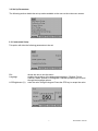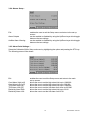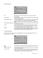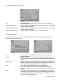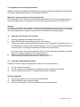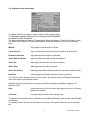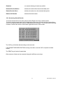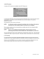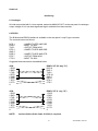
1
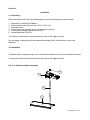
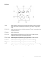
Model 4520
Conductivity/TDS Meter
Operating Manual
452 050/REV A/03-03
Safety
Please read this information carefully prior to installing or using this equipment.
1. The unit described in this manual is designed to be operated only by trained personnel. Any
adjustments, maintenance and repair must be carried out as defined in this manual, by a person
qualified to be aware of the hazards involved.
2. It is essential that both operating and service personnel employ a safe system of work, in addition to
the detailed instructions specified in this manual.
3. References should always be made to the Health and Safety data supplied with any chemicals
used. Generally accepted laboratory procedures for safe handling of chemicals should be employed.
4. If it is suspected that safety protection has been impaired in any way, the unit must be made
inoperative and secured against any intended operation. The fault condition should immediately be
reported to the appropriate servicing authority.
452 050/REV A/03-03
Model 4520
Conductivity/TDS Meter
Operating Manual
Contents
Section 1
Section 2
Section 3
Section 4
Section 5
Section 6
Section 7
Introduction
Instrument Description
Instrument Specification
1.1
1.2
Installation
Unpacking
Installation
Displays
Controls
Inputs/Outputs
2.1
2.2
2.3
2.4
2.5
Operation
Good Practice Guidelines
Set Up Parameters
Preparation of Conductivity Standards
Calibration with Known Cell Constant
Calibration with Standard Solution
Sample Measurement
3.1
3.2
3.3
3.4
3.5
3.6
Maintenance
General
4.1
Optional Accessories
Optional Accessories
5.1
Interfacing
Analogue
RS232
Keypad Emulation
Printing
Alarm Outputs
6.1
6.2
6.3
6.4
6.5
Troubleshooting
Troubleshooting
7.1
EC Declaration of Conformity
452 050/REV A/03-03
Section 1
Introduction
1.1 Instrument Description
A fully specified laboratory Conductivity/Resistivity/TDS/Salinity/Temperature meter that includes full
support for good laboratory practices (GLP). The meter supports 1, 2 or 3 point conductivity
calibration. Powerful data logging capabilities are included with the ability to store up to 500
readings either manually, at timed intervals or alarmed events.
1.2 Instrument Specifications
Conductivity
Ranges
Resolution
Accuracy
TDS
Ranges
Resolution
Accuracy
Temperature
Range
Resolution
Accuracy
ATC Range
Manual Temp. Comp. Range
Outputs
Clock
GLP
Display
Languages
Display
Power
Size
Weight
0 to 19.99µS / 0 to 199.9µS / 0 to 1999µS /
0 to 19.99mS / 0 to 199.9mS / 0 to 1999mS / 0 to 19.99S*
0.01µS / 0.1µS / 1µS / 0.01mS / 0.1mS / 1mS / 0.01S*
*only with cell constant >5
±0.5%±2 digits
0 to 19.99mg/l / 0 to 199.9mg/l / 0 to 1999mg/l /
0 to 19.99g/l / 0 to 199.9g/l / 0 to 1999g/l
0.01mg/l / 0.1mg/l / 1mg/l / 0.01g/l / 0.1g/l / 1g/l*
*only with cell constant >5
±0.5%±2 digits
-10 to +105°C (14 to 221°F)
0.1°C (1°F)
±0.5°C (±1°F)
0 to 100°C (32 to 212°F)
0 to 100°C (32 to 212°F)
Analogue 1mV per 0.01pH
RS232 serial and IrDA printer interface
Alarm - open collector
24 hours, hrs/min/sec or day of month/month/year, leap year
corrected (European and American formats)
Calibration reminder interval (1-999 hours)
Alarm outputs (open collector and audible)
Security code protected user data
Back lit 1/8 VGA monochrome LCD
English, French, German, Italian, Spanish, Portuguese
3½ digit LCD
9V power supply
210x250x55mm
850g
1
452 050/REV A/03-03
Section 2
Installation
2.1 Unpacking
Remove the Model 4520 from the packaging and ensure the following items are included:
1.
2.
3.
4.
5.
6.
Model 4520 Conductivity/TDSMeter
Glass bodied conductivity cell with ATC K=1 (027 013)
Electrode holder
Power Supply (as specified at time of ordering the product)
Condensed operating instructions (452 051)
Operating Manual (452 050)
The electrode stand requires minimal assembly (refer to the diagram below).
Any shortages or damage should be reported immediately to the manufacturer or your local
distributor.
2.2 Installation
The Model 4520 is supplied ready to use. Connect the conductivity cell to the rear panel DIN socket.
The electrode stand requires minimal assembly (refer to the diagram below).
Fig. 2.2.1 Electrode Holder Assembly
4
1
2
3
2
452 050/REV A/03-03
2.3 Displays
1.
Primary display – 4½ digit. Provides direct readout in Conductivity and TDS of samples and
standards.
2.
Mode annunciators – shows selected measurement mode; Conductivity or TDS.
3.
Secondary display – 3½ digit display. Provides direct readout of automatic or manual
temperature.
4.
Mode annunciators – indicates temperature in °C or °F and whether the measurements are
manually temperature compensated (MAN symbol).
5.
Endpoint symbol – this symbol is displayed when an endpoint has been detected.
6.
Mode tags – Each mode tag is highlighted when selected; SETUP, MODE,
STATUS or RESULTS. If a double headed arrow symbol is present this indicates that the
mode can be changed to an alternative option (pH/mV).
7.
Real time clock - will display either date or time.
8.
The following symbols will appear along the display:
Padlock - Set up parameters security locked
Notepad symbol - data logging to internal memory
IrDA status
Alarm indication - an Up arrow refers to Hi alarm / a Down arrow refers to Low alarm
3
452 050/REV A/03-03
2.4 Keypad
1. ESC
used to switch the instrument on and to place into standby mode (only if power
supply lead remains connected to the instrument). Also used to escape/exit a
mode.
2. CAL / CLR
used to select and perform a calibration sequence. This key is also used to clear
readings from Memory.
3. Print key
used to initiate a print.
4. Up Arrow
used for adjustment during set up, to scroll results and to toggle between
Conductivity (µS or mS) and TDS (mg/l or g/l) modes.
5. Down Arrow
used for adjustment during set up, to scroll results and to toggle between
Conductivity µS or mS) and TDS (mg/l or g/l) modes.
6. Left Arrow
used for adjustment during set up and to move between mode tags.
7. Right Arrow
used for adjustment during set up and to move between mode tags.
8. STO
used to accept an entered value in set-up mode and to instigate a stored reading.
This key can also be used as a CAL key during calibration.
4
452 050/REV A/03-03
2.5 Inputs/Outputs
2.5.1 Rear panel layout
1. Conductivity Socket
7 pin DIN socket which allows the conductivity cell to be connected.
2. Alarm Out
2 x 4mm sockets. Open collector alarm output.
3. Output Socket
9 way connection for RS232.
4. Power In
AC 9V I/P socket. 2.1 x 5.5mm socket allowing the power supply to be
connected to the instrument.
5. Analog Out
2 x 4mm sockets. Analogue output (buffered electrode potential).
5
452 050/REV A/03-03
Section 3
Operation
3.1
Good Practice Guidelines
1.
For greatest accuracy ensure no particulate matter is suspended in the solution under test. If
necessary, filter or allow the particles to settle prior to use. Do not allow the cell to come into
contact with any sediment which may be present.
2.
Ensure no air bubbles are trapped in the cell area between the plates.
3.
Ensure the cell plates are completely immersed in the solution under test.
4.
Thoroughly rinse the cell plates in deionised water after use, and for short term storage
immerse the cell in deionised water. Although it is not essential to store the conductivity cell
with the plates in a wetted condition, if they are allowed to dry out completely, initial stability on
re-use may be impaired until the cell plates become re-wetted.
5.
Do not attempt to clean the cell plates as this will remove the black platinization and alter the
calibration and accuracy of the probe. If the cell plates become worn or damaged the plates
should be re-platinised and the cell constant recalculated.
6.
Ensure no salt deposits or particulate matter are allowed to build up around the cell plates or
on the probe body as this may produce a conductivity path lower than that through the
solution. It is recommended that such deposits be removed by soaking the cell in deionised
water. No attempt should be made to wipe off these deposits as this may cause damage to
the cell plates.
7.
Ensure the correct reference temperature is selected for the operating procedures being
used.
6
452 050/REV A/03-03
3.2 Set Up Parameters
The following section details the set-up modes available to the user on the main menu screen:
3.2.1 Instrument Setup
This option will allow the following parameters to be set:
Exit
Language
LCD Brightness (%)
allows the user to exit this menu.
enables the selection of the appropriate language – English, French,
German, Italian, Spanish or Portuguese. Use the Up/Down keys to scroll
through the language options.
enter the value using the keypad. Press the STO key to accept the value.
7
452 050/REV A/03-03
3.2.2 Temperature Setup...
Select the Temperature Setup sub menu by highlighting the option and pressing the STO key. The
following menu will be shown:
Temp units
allows selection of the preferred unit of measurement (either °C or °F) using
the Up/Down keys which toggle between the two units.
Manual temperature
allows the manual temperature value to be set. Press the STO key to
accept the value.
3.2.3 Calibration Set up …
This option allows the following parameters to be set:
Exit
Cell Constant (K)
EC Ratio
Temp Coefficient (%)
enables the user to exit the Setup menu and return to the main set up
screen.
allows setting of the cell constant by using the Up/Down keys. The
Left/Right arrow keys allow forward and backward movement along the
row of digits. Press the STO key to accept the value.
allows setting of the TDS EC ratio between the values of 0.50 and 0.80
(default value of 0.60) by using the Up/Down keys. The Left/Right arrow
keys allow forward and backward movement along the row of digits. Press
the STO key to accept the value.
allows set of the temperature coefficient between the values of 0.00% to
4.00% (default 1.91%) using the Up/Down keys. The Left/Right arrow keys
allow forward and backward movement along the row of digits. Press the
STO key to accept the value
8
452 050/REV A/03-03
Reference Temp
Ultra-Pure Temp
Correction
allows the reference temperature to be set to 18, 20 or 25°C (default 25°C)
using the Up/Down keys which toggle between the values.
this option can be enabled or disabled by using the Up/Down keys which
toggle between the two options.
3.2.4 Calibration Buffer Setup...
Select the Calibration Buffer Setup sub menu by highlighting the option and pressing the STO key.
The following menu will be shown:
Exit
Cal Buffers Used
Cal Buffer Set
Cal 1 Buffer (mS)
Cal 2 Buffer (mS)
Cal 3 Buffer (mS)
enables the user to exit the Setup menu and return to the main set up
screen.
allows selection of 1, 2 or 3 point calibration.
allows selection of Auto Recognition or Manual Entry of buffers. Selection of
the preferred option can be made using the Up/Down keys which toggle
between the two options.
allows Cal 1 manual buffer value to be set using the Up/Down keys. The
Left/Right arrow keys allow forward and backward movement along the
row of digits. Press the STO key to accept the value.
allows Cal 2 manual buffer value to be set using the Up/Down keys. The
Left/Right arrow keys allow forward and backward movement along the
row of digits. Press the STO key to accept the value.
allows Cal 3 manual buffer value to be set using the Up/Down keys. The
Left/Right arrow keys allow forward and backward movement along the
row of digits. Press the STO key to accept the value.
9
452 050/REV A/03-03
3.2.4 Alarms Setup...
Exit
Alarm Outputs
Audible Alarm Warning
enables the user to exit the Setup menu and return to the set up
screen.
can be enabled or disabled by using the Up/Down keys which toggle
between the two settings.
can be enabled or disabled by using the Up/Down keys which toggle
between the two settings.
3.2.5 Alarm Point Settings....
Select the Calibration Buffer Setup sub menu by highlighting the option and pressing the STO key.
The following menu will be shown:
Exit
Cond Alarm High (mS)
Cond Alarm Low (mS)
TDS Alarm High (g/l)
TDS Alarm Low (g/l)
Resistivity Alarm High
Resistivity Alarm Low
enables the user to exit the Setup menu and return to the main
set up screen.
allows the user to set the high alarm limit up to 1999.999
allows the user to set the high alarm limit up to 000.000.
allows the user to set the high alarm limit up to 1999.999
allows the user to set the low alarm limit down to 000.000
allows the user to set the high alarm limit up to 20.00
allows the user to set the low alarm limit 00.01
10
452 050/REV A/03-03
3.2.6 G.L.P Setup …
Exit
enables the user to exit the Setup menu and return to the main
set up screen.
Cal Reminder
can be enabled or disabled by using the Up/Down keys which toggle
between the two settings.
Cal Reminder Interval
can be set within the limits of 001 to 999 hours by using the Up/Down
keys.The Left/Right arrow keys allow forward and backward
movement along the row of digits. Press the STO key to accept the
value.
Cal Reminder Audible Alarm can be enabled or disabled by using the Up/Down keys which toggle
between the two settings.
User ID
up to a 4 digit code can be set using the Up/Down keys. The Left/
Right arrow keys allow forward and backward movement along the
row of digits. Press the STO key to accept the value.
Batch ID
up to a 3 digit code can be set by using the Up/Down keys.The Left/
Right arrow keys allow forward and backward movement along the
row of digits. Press the STO key to accept the value.
3.2.7 Security Setup …
Select the Security Setup sub menu buy highlighting the option and pressing the STO key. The
following menu will be shown:
Exit
menu
Data Entry Security
Security Code
enables the user to exit the Set Up menu and return to the previous
.
can be enabled or disabled by using the Up/Down keys which toggle
between the two settings.
up to a 3 digit code can be set by using the Up/Down keys.The Left/
Right arrow keys allow forward and backward movement along the
row of digits. Press the STO key to accept the value.
11
452 050/REV A/03-03
3.2.8 Data Logging Set up …
Exit
Data Log Event
Data Log To
Data Log Interval
Memory Full
Prompt Before Deleting
Clr Key
enables the user to exit the Set Up menu and return to the main
set up screen.
can be enabled or disabled by using the Up/Down keys which toggle
between the two settings.
allows the data to be sent to Memory or to the external Printer.
Selection is made via the Up/Down keys which toggle between the
two settings.
can be set between 00:00:01 and 23:59:59.
gives the user to select the Stop (cease storing results and not to
overwrite existing stored information) or Overwrite (overwrite existing
results) options when the memory is full. Selection is made via the
Up/Down keys which toggle between the two settings.
can be enabled or disabled by using the Up/Down keys which toggle
between the two settings.
toggles between Deletes Results Before, Deletes All Results and
Deletes Results Since. Selection is made via the Up/Down keys
which toggle between the two settings.
3.2.9 Printer Setup …
Select the Printer Setup sub menu buy highlighting the option and pressing the STO key. The
following menu will be shown:
Exit
Printer Interface
Serial Printer Baudrate
enables the user to exit the Setup menu and return to the main
instrument display.
toggles between Infrared and Serial. Selection of the preferred option
can be made using the Up/Down keys which toggle between the two
settings.
toggles between 9600 and 1200. Selection of the preferred option
can be made using the Up/Down keys which toggle between the two
settings.
12
452 050/REV A/03-03
3.2.10 Endpoint Detection Set up …
Exit
Endpoint detection
Endpoint Audible Alarm
Endpoint Stability (Sec)
enables the user to exit the Set Up menu and return to the main
instrument display.
can be enabled or disabled by using the Up/Down keys which toggle
between the two settings.
can be enabled or disabled by using the Up/Down keys which toggle
between the two settings.
can be set within the limits of 001 TO 999 SECONDS.
3.2.11 Clock Set up …
Select the Clock Setup sub menu buy highlighting the option and pressing the STO key. The
following screens will be shown:
Exit
Display
Date Format
Time
Date
enables the user to exit the Setup menu and return to the main
instrument display.
toggles between Time and Date. Selection of the preferred option
can be made using the Up/Down keys which toggle between the two
settings.
toggles between European (DD/MM/YY) and American (MM/DD/YY)
formats. Selection of the preferred option can be made using the Up/
Down keys which toggle between the two settings.
allows time to be set (hrs/min/sec) using the Up/Down
keys. The Left/Right arrow keys allow forward and backward
movement along the row of digits. Press the STO key to accept the
setting.
allows date to be set (in previously selected format – European or
American) using the Up/Down keys. The Left/Right arrow keys allow
forward and backward movement along the row of digits. Press the
STO key to accept the setting.
13
452 050/REV A/03-03
3.3 Preparation of Conductivity Standards
Suitable conductivity standards are available commercially or these can be made up as required from
A.R. grade reagents with reference to relevant physical tables.
Method for general purpose Conductivity Standard
Accurately weigh out 0.746 grammes of dried A.R. grade Potassium Chloride (KCl) and dissolve in 1
litre of good quality water. This produces a 0.01N solution with a conductivity of 1413µS at 25°C.
Storage
This solution must be stored in a plastic container and the air space above the solution should be kept
to an absolute minimum. The shelf life of 1 week can be increased by storing below 4°C, but where
any doubt exists about the viability of stored solution a fresh batch should be prepared.
3.4
Calibration with Known Cell Constant
1.
2.
3.
Connect a standard pre-calibrated cell to the unit.
Select SETUP mode on the display using the Left arrow key.
Set the cell constant value as indicated on the body of the conductivity cell (refer Section 3.2.1)
The standard X1.0 cell has a cell constant range from 0.8 to 1.20 and is generally calibrated to
2 decimal places. The display should be set to indicate this figure exactly.
4.
5.
The X10 cell has a cell constant range from 8.0 to 12.0 and is generally calibrated to 2 decimal
places. The display should be set to indicate this figure.
Set the Temperature Coefficient value (refer Section3.2.2).
Select the required reference temperature (refer Section 3.2.3).
3.5
Calibration with Standard Solution
Calibration of the unit and cell with standard solutions will only be necessary if:
1)
2)
3)
The cell constant is unknown.
The cell constant has changed due to replatinising, wear or damage to the plates.
An ATC slope other than 2%/°C is required (refer Special Calibration).
General Calibration
1)
2)
3)
Immerse the conductivity cell into the prepared standard.
Select the MODE menu using the keypad.
Press the CAL/CLR key. The unit will calibrate to the nearest standard.
14
452 050/REV A/03-03
3.6 Sample Measurement
General
Conductivity is a temperature dependent measurement. All substances have a conductivity
coefficient which varies from 1% per °C to 3% per °C for most commonly occurring substances.
The automatic temperature compensation on the 4520 defaults to 1.91% per °C, this being
adequate for most routine determinations.
Conductivity readings varying with temperature may be due to the substances under test having a
coefficient other than the typical value of 1.91% per °C. To eliminate this variation it is necessary to
maintain all samples at the reference temperature by use of a thermostatic water bath or
equivalent.
Adjustment may be made by entering the SETUP menu and selecting COEFF (refer Section 3.2.2).
The reading can then be adjusted to the required value (0.00 to 4.00) by using the keypad.
Sample Measurement
After calibration the measurement of samples is carried out by immersing the cell in the samples,
allowing the readout to stabilise, and recording the result. The cell should be rinsed in deionised
water between each sample to avoid contamination, shaken to remove internal droplets, and the
outside wiped prior to immersion in the next sample.
On completion of sample measurement the cell should be thoroughly rinsed in deionised water.
Storage
Short Term
Long Term
NOTE:
the cell should be immersed in deionised water to keep the plates wetted.
the cell should be thoroughly rinsed in deionised water, the exterior body
wiped and then stored dry.
When preparing the cell for storage the plate area MUST NOT be wiped dry.
When using a dry cell initial stability on re-use may be impaired until the cell
plates become re-wetted.
To obtain optimum performance refer to Section 3.1 - Good Practice Guidelines.
15
452 050/REV A/03-03
3.7 Status Page
The Status page displays the current calibration information.
If no valid calibration data is stored (e.g. after a reset or a failed calibration) the warning screen:
will be shown.
The status page will show the calibration data in the order it was carried out. Date, time,
temperature and Conductivity/TDS readings will be displayed for each standard.
16
452 050/REV A/03-03
3.8 Results storage and display
The Model 4520 has a variety of options relating to the storage of data.
To initiate data logging the Data Log Event setting should be ENABLED.
By default this option is MANUAL.
The settings available are: Manual, Timed Interval, Endpoint Detection, Timed After Endpoint, Alarm
Set, Alarm Clear, Alarm Set & Clear and Disabled. Press the Up/Down arrows to cycle through
them.
Manual
- logs results on pressing the STO key.
Timed Interval
- logs on time and interval set by Data Log Interval in Hr:Min:Sec.
Endpoint Detection
- logs data when the endpoint is detected.
Timed After Endpoint
- logs at the Data Log Interval after the endpoint.
Alarm Set
- data logs when the alarm set point is reached.
Alarm Clear
- data logs when the alarm is cleared.
Alarm Set & Clear
- data logs at the alarm set point and when the alarm condition clears.
Disabled
- no data logging is possible when this option is selected.
The 4520 can log to either the memory or the printer. The memory can hold 500 data points which
can be accessed via the Results screen.
When the memory is full there are two options available regarding any additional logging. The
default is STOP.
Stop
- when the memory is full no further data logging can occur until some
locations are deleted.
Overwrite
overwrites data from the earlier storage point.
To prevent the accidental erasure of data the "Prompt Before Deleting" option can be either Enabled
or Disabled.
The function of the CLR key can also be set in this menu. The options define the use of the delete
key.
17
452 050/REV A/03-03
Disabled
- no manual deleting of results is possible.
Deletes Results Before
- deletes all results before the selected data point.
Delete Results Since
- deletes all results since the selected data points.
Deletes All Results
- deletes all stored results.
3.8.1 Accessing Stored Results
To access results which have been stored use the Right arrow key to select results.
The most recently stored results will be displayed on the screen. If more results are stored than
can fit on a single screen then a series of data screens are available. The current screen and total
number of screens are shown in the bottom right hand corner of the screen.
The CLR key will delete data according to the set mode.
If the PROMPT BEFORE DELETING warning is set then a second CLR is required to delete
results.
The PRINT key will print all stored data.
Other screens of data can be accessed using the Up/Down arrow keys.
18
452 050/REV A/03-03
3.9 GLP Functions
A variety of GLP functions are available via the GLP Setup menu.
A reminder that calibration is due can be set via the Cal Reminder option. Once this option is set a
valid calibration is required to use the 4520 after the time limit has elapsed. This option is
DISABLED by default.
The interval time is set in hours on this menu.
NOTE:
A calibration should be performed immediately after the setting of this value to
reset the clock. This should be done as soon as set up is complete.
The on screen reminder can be accompanied by an audible alarm this is set using the audible
alarm setting on this menu.
NOTE:
The use of the Calibration Reminder feature will prevent the user from
performing measurements with the 4520 until a valid calibration is carried out.
The user and batch ID can be used to identify sets of samples and a specific user. This information
is printed when data is output to the printer. The batch number is also stored in the results memory.
3.13.1 Security
To control access to set up options and data manipulation functions a security code can be set
using this menu. When enabled a password is required to make any changes to the set up menus.
When the code is ENABLED a user can measure a sample, log data and calibrate the unit, but
cannot change settings within the set up screens until a valid password is entered.
19
452 050/REV A/03-03
Section 4
Maintenance
4.1 General
The Model 4520 is designed to give optimum performance with minimum maintenance. It is only
necessary to keep the external surfaces clean and free from dust. To give added protection when
the unit is not in use the unit should be disconnected from the mains supply and covered with the
optional dust cover (060 406). For longer term storage or re-shipment it is recommended that the
unit be returned to the original packing case.
All conductivity cells should be thoroughly rinsed after use and stored in deionised water. Do not
attempt to clean the surface of the plates as this could result in damage to the black platinised
surface.
Section 5
Optional Accessories
5.1
Optional Accessories
060 406
037 701
037 801
050 002
Dust cover
IrDA printer supplied with roll of thermal paper, serial connection lead, power
supply, power connection lead (UK) and pouch
Interface cable kit
Serial communication software (3½” disk)
Conductivity Cells
027 013
Conductivity Cell K=1
027 113
Conductivity Cell K=0.1
027 114
Conductivity Cell K=1 (plastic covered)
NOTE: The cells listed below are glass free and epoxy bodied.
027 211
027 212
027 213
Conductivity Cell with ATC K=0.1
Conductivity Cell with ATC K=1
Conductivity Cell with ATC K=10
Calibration Standards
025 138
1413µS Standard (500ml)
025 156
12.88mS Standard (500ml)
025 164
84µS Standard (500ml)
025 139
10µS Standard (500ml)
025 165
1382ppm TDS Standard (500ml)
037 702
021 030
021 031
021 032
021 033
Paper roll, thermal
UK 230V power supply
European 230V power supply
US 115V power supply
230V leaded power supply
20
452 050/REV A/03-03
Section 6
Interfacing
6.1 Analogue
All units are provided with 2 x 4mm sockets, marked as ANALOG OUT, on the rear panel. An analogue
output voltage of 1mV per least significant digit is available from these sockets.
6.2 RS232
The Bi-directional RS232 interface is available on the rear panel 9 way D type connector.
The connections are as follows:
DCD 1
RXD 2
TXD 3
DTR 4
GND 5
DSR 6
RTS 7
CTS 8
- LINKED TO DTR AND DSR
- INPUT TO 4520
- OUTPUT FROM 4520
- LINKED TO DCD AND DSR
- LINKED TO DCD AND DTR
- OUTPUT FROM 4520
- INPUT TO 4520
Suggested interconnections are detailed below:
4520
1 DCD
2 RXD
3 TXD
4 DTR
5 GND
6 DSR
7 RTS
8 CTS
9
IBM PC XT (25 way “D”)
DCD 8
RXD 3
TXD 2
DTR 20
GND 7
DSR 6
RTS 4
CTS 5
4520
1 DCD
2 RXD
3 TXD
4 DTR
5 GND
6 DSR
7 RTS
8 CTS
9
IBM PC XT (9 way “D”)
1 DCD
2 RXD
3 TXD
4 DTR
5 GND
6 DSR
7 RTS
8 CTS
9
NOTE:
Inerface Cable (Order Code: 013 203) is required.
21
452 050/REV A/03-03
Interfacing (continued)
The RS232 communications parameters on the computer or printer need to be set to match those of
the Model 4510, as detailed below:
1200 Baud
7 Data Bits
Odd Parity
1 Stop Bit
9600 Baud
8 data bits
No parity
1 stop bit
OR
Setting of these options is detailed in Section 3.6.6.
The Model 4520 supports both hardware (CTS/RTS) flow control and software XON/XOFF flow control.
Pressing the PRINT key outputs from the RS232 interface.
Sending an ASCII “D” to the 4520 causes a printout of the current displayed reading plus sample
number.
Sending an ASCII “C” causes a printout of the last calibration parameters.
Sending an ASCII "P" causes a printout of the stored readings.
6.3 Keypad Emulation
Keypad remote control using RS232 interface:
7
- Instrument On / Standby / Escape
1
- Calibrate / Memory Clear
9
- Print
8
- Up Arrow
2
- Down Arrow
4
- Left Arrow
6
- Right Arrow
3 or 5
- Enter / Store
22
452 050/REV A/03-03
6.4 Printing
A 32 column serial printer (037 701) is available for use with the Model 4520.
There are two methods of connecting the serial printer to the Model 4520:
a) IrDA - the IrDA interface is a line of sight, wireless communication protocol. The IrDA sensor
(located on the front left hand corner of the printer) should be in line with the Ir window on the side of
the 3520. The Ir icon on the symbol display indicates whether the units are attempting to connect
(single icon flashing) or connected (two icons).
b) Connect serial cable supplied with the printer to the 9 way socket located on the rear panel of the
instrument.
To intiate a print out of data press the print key.
When the first print is performed a header section will be printed showing:
Instrument name
Time and Date
Spacing for entry of Operator & User ID
Most recent calibration information (Cell constant)
Reference temperature
Temperature coefficient
TDS EC Ratio
This will be followed by results data in either Conductivity or TDS dependent on mode selected.
Details will also be given on temperature. Time and date of the stored readings will be displayed.
An asterisk (*) indicates that manual temperature compensation is being used.
Each reading will be identified by a batch number.
A calibration will reset the printout and the header information will be re-printed.
To obtain a print out of stored readings, enter the RESULTS MODE and press the print key. A print
out of all filled memory locations will then be generated.
6.5 Alarm Outputs
The 4520 provides two alarm outputs. These can be accessed using the two 4mm connectors on
the rear of the 4520. They are open collector outputs. To set the alarm limts at which these are
activated, please refer to section 3.2.4.
To use the alarm outputs, they should be ENABLED in the Alarms Setup screen see section 3.2.4
They will operate in both pH measurement and absolute millivolts. The alarm outputs will remain
active until the alarm condition is no longer evident or the alarm limits are reset in the Alarm Set up
menu.
For the Hi alarm output please use the Red 4mm phone connector.
For the Low alarm output please use the Black 4mm Phono connector.
For further information please contact your local distributor or the manufacturer.
23
452 050/REV A/03-03
Section 7
Troubleshooting
7.1Troubleshooting
Fault
Possible Cause
Action
No display
Check power supply
Check that correct 9V ac power supply
is connected and switched on.
Erratic display
Check power supply
Unit must be used with supplied 9V
acpower supply. Usage of other units will
cause the 4520 not to operate.
Unstable display
Conductivity cell defective
Replace conductivity cell.
Display permanently
under or over range
Intermittent or no connection
Conductivity cell defective
Contaminated solutions
Check cell connection to 4510.
Replace conductivity cell
Replace solutions
Intermittent display
Conductivity cell not fitted
correctly
Check connections.
Reading drifts
Conductivity cell stored dry
CO2 absorbtion by sample
Allow to soak for 2 hours
Noticeable for low conductivity - do not
allow sample to stand in unstoppered
bottles.
Non linear readings
Conductivity cell not zeroed
Zero conductivity cell.
Poor reproducibility
Carryover between solutions
Rinse cell in distilled water between
measurements.
Will not print
IrDA connection broken
Line up units or alternatively use
supplied RS232 connector.
The feed light on the printer will flash if
the unit requires paper.
Connect ac power supply.
Paper out
Battery flat
If the above does not answer your query try the FAQ section on the www.Jenway.com Website.
24
452 050/REV A/03-03
EC Declaration of Conformity
JENWAY Model 4520 Conductivity/TDS Meter complies with the following European Standards:
EN 50081-1:1992 Electromagnetic compatibility - Generic emission standard
EN 50082-1:1992 Electromagnetic compatibility - Generic immunity standard (Performance criterion B)
EN 61010-1:2001 Safety requirements for electrical equipment for measurement, control and
laboratory use
Following the provision of:
EMC Directive - 89/336/EEC and Low Voltage Directive - 73/23/EEC
Martyn J. Fall
Managing Director, Jenway
Gransmore Green, Felsted, Dunmow,
Essex, CM6 3LB, England
25
452 050/REV A/03-03