1
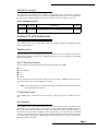
CS-4000 Release Notes
Version 6.1.1
Document Number: 46-700 Rev. H
November 1997
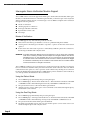
About This Release Notes Package
This Release Notes package includes information about new UL information, new version
6.1.1 software, and how to install the software. These changes affect the CS-4000 Central
Station Receiver Installation and User’s Manual (46-056).
Replace Appendix F Underwriters Laboratories Installations dated 7/24/91, 5/95, and July
1996 with Appendix F dated November 1997.
Add Appendix N: CS-4000 Software Release 5.0
Add Appendix O: CS-4000 Software Release 5.3
Add Appendix P: CS-4000 Software Release 6.0
Add Appendix Q: CS-4000 Software Release 6.1.1
ITI, CareTaker, Commander, RF Commander, Interrogator, and LifeGard are registered
trademarks of Interactive Technologies, Inc. UltraGard and SIMON are trademarks of
Interactive Technologies, Inc.
CS-4000 Release Notes
CS-4000 Central Station Receiver Release Notes
Document Number: 46-700 Rev. H
November 1997
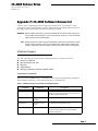
APPENDIX F: UNDERWRITERS LABORATORIES
INSTALLATIONS
GENERAL - (all applications)
1) The CS-4000 DACR shall be used with the UL Listed Signaling Device Model DMP106, LX-810,
or MicroLine 184 Turbo printers. The printer shall be mounted within 20 feet of the receiver. The
Epson LX-810 printer shall employ the INMAC 8214 Surge Protector to protect the AC input.
The Okidata MicroLine 184 Turbo shall be connected to a 120 VAC, 60 Hz line source through
the listed Proxima Model S100 Suppressor.
2) The UL Listed Signaling Device p/n 218600201A keyboard shall be used.
3) The printers shall be connected to a Listed uninterruptible power supply and/or engine driven
generator to provide 24 hours of required backup.
4) A spare receiver and annunciator shall be provided at the Central Station to comply with the
requirements of a 30-second replacement.
5) At least two password levels shall be employed. The default master code shall be changed at
installation.
6) The "Power Fault" options shall be left "ON."
7) The "Quiet" option shall be "OFF."
8) The "Alert" option shall be "ON."
9) The "Alert Interactive" option shall be "ON."
10) The "Alert Waiting" option shall be "ON."
11) The "Silent" option shall be "OFF."
12) Refer to Section 7.2 for those control units/formats which have been determined compatible by
UL.
13) The "TRAP" command shall not be used for UL Listed ITI systems providing Home Health Care
Signaling Service.
14) Operation of the CS-4000 DACR with peripherals other than the three printers above, has not
been investigated by UL.
15) The alarm code conversions shall be made as described in Section 7.2.
16) Connection to other equipment as determined by Underwriters Laboratories as being compatible shall be completed within 20 feet and in the same room as the CS-4000 DACR.
17) The RS-232 Interface Jack 3 has no connection. (This is an addition to the UL statements on page
i.)
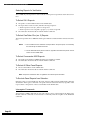
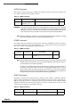
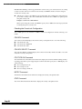
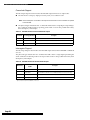
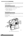
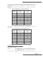
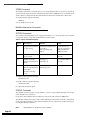
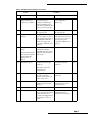
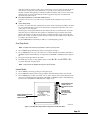
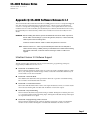
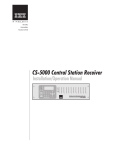
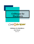
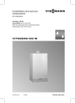
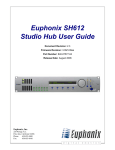
18) The diagram on the following page shows the required routing of field wiring, to and from the
receiver.
Note:
AC, battery, and alert output relay wiring shall be routed away from all other power limited wiring
as shown in the diagram on the following page. A minimum of 1/4 inch spacing shall be maintained. It is recommended that the phone lines be bundled and tie-wrapped to maintain spacing for
power limited wiring. (This is an update to the wiring on page 5.)
Page 1
CS-4000 Central Station Receiver Release Notes
CS-4000 Rear Connections and Components
RS-232
CABLES
PROGRAMMING
PHONE LINE
CS-4000 BACK VIEW
PHONE LINE
CABLES
1
2
PROGRAMMING
PHONE LINE
3
4
+
SLO-BLO
2 AMP
12V BATTERY
-
FAULT
RESET
BUTTON
FAULT RESET
lead acid only
BATTERY
CABLE
NO
CONNECTION
3
WARNING: Do not open. No serviceable parts inside.
MONITORING AND
PROGRAMMING
PHONE INPUTS
1
2
RS-232 INTERFACE JACKS
RS-232 JACKS TO
INTERFACE TO A
COMPUTER, PRINTER
OR TERMINAL
MAINTAIN
AT LEAST
1/4" SPACING
30 Watts Max.
ALERT OUTPUT
RELAY
POWER FUSES
NC-NO-C
FUSE RATING
115V, 2A SLO-BLO
230V, 1A SLO-BLO
CAUTION:
FOR CONTINUED FIRE
PROTECTION REPLACE FUSE
WITH SAME TYPE AND RATING.
70 WATTS MAX.
POWER RATING
115 VAC. 50-60 HZ:
AC POWER
CORD
EXTERNAL
SIREN ALERT
CONNECTION
ALERT
CABLE
1004G13A.DS4
Page 2
CS-4000 Release Notes
CS-4000 Central Station Receiver Release Notes
Document Number: 46-700 Rev. H
November 1997
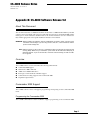
Appendix N: CS-4000 Software Release 5.0
About This Document
This document describes CS-4000 enhancements made in the CS-4000 Extended Memory Module
software version 5.0 (80-105). This version provides full support for the Commander® 2000, and the
Interrogator™ Alarm Verification Module. Refer to the CS-4000 Installation and User’s Manual (46056) and the appropriate control panel installation manuals for more details.
WARNING: Before installing this software, perform an MSTATUS command to obtain a printout of the
CS-4000’s current settings. If you are using the E31, E3X, E41, or E42 commands, obtain a
printout of their settings also.
Note: Software version 5.0 will not work on a CS-4000 that does not have 64K of random-access
memory (RAM). Make sure your CS-4000 is a part number 60-197-64K before attempting to
install this software. If you do not have 64K, contact ITI Order Processing at 1-800-777-4841
for an upgrade.
Overview
The CS-4000 software version 5.0 includes the following enhancements:
Commander 2000 support
Enhanced CS-4000 commands
Additional CS-4000 modifications
Interrogator Alarm Verification Module support
Communication locking support for the Commander 2000
Expanded output formats
Commander 2000 Support
The CS-4000 software version 5.0 supports programming and reporting for the Commander 2000
Panel.
Programming the Commander 2000
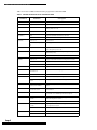
The CS-4000 commands have been modified to support programming of the Commander 2000.
Page 1
CS-4000 Central Station Receiver Release Notes
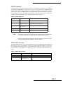
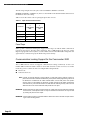
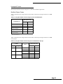
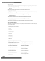
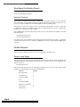
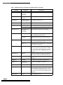
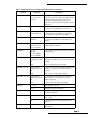
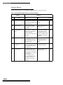
Table 1 shows the CS-4000 commands used to program the Commander 2000.
Table 1. CS-4000 Commands for the Commander 2000
Command
Description
ACCESS nnnn
Any four numbers
Assigns access code nnnn to the Panel.
ACCOUNT nn-nnn
Any five letters or numbers
Assigns account number nn-nnn to the Panel.
BATTLIFE n
From 2 to 255
Assigns n hours for the Panel to run on battery backup before
entering shutdown mode.
BYPASS n
From 1 to 18
Bypasses sensor n.
CPUTIME n
‘SET’
Assigns the CS-4000’s current time to the Panel.
‘STATUS’
Returns the Panel’s time setting to the CS-4000.
From 1 to 18
Deletes sensor n.
From 80 to 98, except 88 and
97
Deletes upper sensor n.
DURESS nn
Any two numbers
Assigns duress code aann to the Panel, where aa are the first two
digits of the primary access code.
ENTRY n m
From 8 to 88
Rounds n seconds down to a multiple of eight and assigns as the
standard entry delay.
From 1 to 8
Assigns m minutes for extended entry and exit delay.
From 1 to 14
Displays event buffer information for the previous n events.
‘ALL’ or ‘’
Displays all event buffer information.
‘CLEAR’
Empties the event buffer.
EXIT n
From 8 to 88
Assigns n seconds for exit delay, rounded to a multiple of 8.
GROUP n m
n from 1 to 18
m from 00 to 29
Assigns sensor number n to group m.
HOUSE n
From 1 to 255
Assigns house code n to the Panel.
INITIALIZE n
18
Adds sensor 18 to the system configuration.
From 80 to 98, except 88,
and 97
Adds upper sensor n to the system configuration.
MACCESS m nnnn
m from 1 to 5
nnnn any four numbers
Assigns secondary access code nnnn to secondary access code
user m.
OPTION Fn m
n from 20 to 27
m either ON or OFF
Turns ON or OFF feature number n. See Table 2 for feature number information.
PFORMAT n
From 0 to 2
Assigns phone communication format n for central station reporting. See Table 3 for PFORMAT parameter descriptions.
PHONE n
Up to 18 digits, including *,
#, and D.
Assigns phone number n to the primary phone number,
with 3-second pauses for each D.
‘OFF’
Removes the primary phone number.
Up to 18 digits, including *,
#, and D.
Assigns phone number n to secondary phone number, with
3-second pauses for each D.
‘OFF’
Removes the secondary phone number.
1, 2, or 3
Arms the Panel to Level n.
8 or 9
Enters the Panel into test mode n.
DELETE n
EVENT n
PHONE2 n
PLEVEL n
Page 2
Parameters
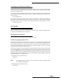
CS-4000 Central Station Receiver Release Notes
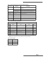
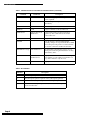
Table 1. CS-4000 Commands for the Commander 2000 (Continued)
Command
Parameters
Description
PMODE n
From 0 to 5
Enables phone mode n. See Table 4 for PMODE parameter
descriptions.
PTFREQ n m
n from 1 to 255
Assigns automatic phone test frequency to once every n days.
m less than or equal to n
Assigns m as the days remaining until the next phone test.
RELEASE
n/a
Releases the trapped panel, as well as the phone line.
RESTORE n
From 1 to 18
Restores bypassed sensor n.
SIREN n
From 2 to 15
Assigns n minutes as the siren time out.
STIME n
Military time, from 0000 to
2359
Assigns military time n hours for the next 24-hour supervisory.
SUPSYNC n
From 2 to 24
Assigns n hours for supervisory check-in period.
ZONES
n/a
Displays all zone information.
Table 2. Commander 2000 Feature Numbers
Feature
Nbr
Condition
Name
ON
OFF
Default
F20
Interrogator
Interrogator Module is enabled.
Interrogator Module is disabled.
OFF
F21
DC Power Supply
DC line power is monitored.
AC line power is monitored.
OFF
F22
Dialing format
DTMF dialing format is used.
Pulse dialing format is used.
ON
F23
Event Buffer
Only retains openings and closings.
Retains all events.
OFF
F24
Hardwire input state
Normally open (N/O).
Normally closed (N/C).
OFF
F26
Command button disarm
Quick disarm (CMD + 1) is enabled.
Quick disarm is disabled.
OFF
F27
Panel alarm mute
Panel does not make siren output.
Panel makes siren output.
OFF
Note: Feature numbers F0-F17 are not compatible with the Commander 2000.
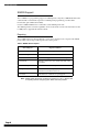
Table 3. Phone Formats
PFORMAT n
Description
0
ITI
1
4/2, 1400 Hz
2
4/2, 2300 Hz
Page 3
CS-4000 Central Station Receiver Release Notes
Table 4. Phone Modes
PMODE n
Description
0
All calls report to phone 1.
Phone 2 is never used.
1
All calls report to phone 1.
On failure, calls report to phone 2.
2
Alarms and cancels report to phone 1.
Supervisories and low batteries report to phone 2.
3
Alarms and cancels report to phone 1.
All calls report to phone 2.
4
Alarms and cancels report to phone 1, but not
open/close reports.
All calls report to phone 2.
5
Alarms and cancels report to phone 1 in 4/2 format.
All calls report to phone 2.
Reporting from the Commander 2000
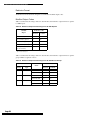
The CS-4000 software has been modified to accept sensor and upper sensor reports from the Commander 2000.
Sensor Reports
A panel reports several kinds of conditions to the CS-4000. Table 5 shows the possible reports from a
Commander 2000. Sensor numbers range from 01 to 18 and are represented by nn below.
Table 5. Sensor Reports from the Commander 2000
Sensor Report
Page 4
Report Condition
nn Alarm!
Armed sensor nn is tripped.
nn Alarm Tamper
Cover is removed on armed sensor nn.
nn Cancelled
Alarm from tripped sensor nn is cancelled by a user.
nn Exit Fault
Exit door sensor nn is not closed at the end of the exit delay.
nn Low Battery
Sensor nn has a low battery.
nn Supervisory
SUPSYNC time has expired, and no transmission has been
received from sensor nn.
nn Trouble
The EOLR on a hardwire loop is tripped.
CS-4000 Central Station Receiver Release Notes
Upper Sensor Reports
A panel sends an upper sensor report to the CS-4000 when the corresponding upper sensor number
is ON and the report condition is encountered. Table 6 shows the condition that must exist for the
upper sensor reports sent by the Commander 2000.
Table 6. Upper Sensor Reports from the Commander 2000
Upper Sensor Report
Default
Report Condition
80 Alarm!
ON
Pressing the FIRE emergency button.
81 Alarm!
ON
Pressing the POLICE emergency button.
82 Alarm!
ON
Pressing the AUXILIARY emergency button.
83 Phone Test
ON
Phone test mode.
84 Opening Report User #
OFF
User # disarms the system.
85 Closing Report User #
OFF
User # arms the system.
86 Alarm! Silent Duress!
ON
Entering the duress code, followed by any arming level.
87 Auto Force Armed
OFF
The system automatically bypasses a sensor after the panel protests an open sensor during arming.
The user indirectly bypasses a sensor when the panel protests an
open sensor during arming.
89 Low Battery Unit #
89 Supervisory Unit #
OFF
Touchpad unit # has a low battery.
Touchpad unit # has not reported for SUPSYNC time.
90 AC Power Failure
90 Alarm Restoral
OFF
The Panel’s AC power is interrupted for 15 minutes.
AC power is restored after a failure.
91 CPU Shut Down
91 Low CPU Battery
91 Alarm Restoral
ON
On battery backup, one minute before BATTLIFE expires.
The Panel detects a low battery.
The Panel detects a good battery, after a low battery was detected.
92 Alarm! Tamper Loop
ON
The cabinet tamper is tripped while the Panel is armed to level 2
or 3.
93 Automatic Phone Test
OFF
Automatic phone test, which occurs at a predetermined interval.
94 Receiver Failure!
ON
The Panel does not receive a transmission from any transmitter for
two hours.
95 CPU Back in Service
OFF
AC power is restored after the Panel has gone into shutdown
mode.
†
OFF
The event buffer automatically dumps after storing 12 events.
87 Force Armed
98 Auto Event Dump
† After the CS-4000 displays this message, the CS-4000 automatically instructs the panel to report all events and then clears the panel event
buffer.
Page 5
CS-4000 Central Station Receiver Release Notes
Enhanced CS-4000 Commands
The CS-4000 software version 5.0 includes modifications to previously available commands and the
new DAYSAVE command.
Modified CS-4000 Commands
The modified CS-4000 commands and their changes are shown in Table 7.
Table 7. Modified CS-4000 Commands
Command
Change
BLIFE, or BATTLIFE
1. New valid range for the RF Commander® is 1-126.
2. Command not allowed for RF Commander (rev. 2.5 and earlier).
CHANNEL n VERSION mm
CHANNEL n command now has the VERSION option. Valid mm options are V4 and V5,
V5 being the default.
DELETE
Command can now be entered as DEL.
E31, E3x, E41, E42
Added PHONETEST to the list of assignable keywords.
GROUP
Group 29 is now valid for CareTaker® Plus (rev. 2).
HOUSE
House code 0 is not allowed for CareTaker Plus (rev. 2).
OPTION
F21 and F22 are now valid for the CareTaker Plus (rev. 2). See Table 8 for feature number
information.
PHONE
1. Panels dialing in DTMF format accept * and # values.
2. PHONE OFF command does not remove phone if PMODE 5 is set.
PHONE2
1. Panels dialing in DTMF format accept * and # values.
2. PHONE2 OFF command does not remove phone 2 if PMODE 5 is set.
PMODE
Phone 1 and 2 must exist to change to PMODE 5.
SUPSYNC
CareTaker Plus new valid range is: 2-24.
ZONES
Eliminated display of battery and open/close messages for nonapplicable upper sensor
numbers.
†
‡
† V5 configures new output codes for the CS-4000 version 5.0 software enhancements. V4 configures output codes similar to the CS-4000 version
4.0 software output codes. See “Expanded Output Formats” for details on the enhancements.
‡ This prevents accidental elimination of calls to the only phone number assigned the ITI format.
Table 8. Additional CareTaker Plus (rev. 2) Feature Numbers for the OPTION Command
Feature
Nbr
Page 6
Condition
Name
ON
OFF
Default
F21
Supervisory
trouble beeps
Supervisories generate immediate beeps.
Supervisories generate delayed beeps.
OFF
F22
Dialing format
DTMF dialing format is used.
Pulse dialing format is used.
OFF
CS-4000 Central Station Receiver Release Notes
DAYSAVE Command
The DAYSAVE command allows the CS-4000 to automatically adjust its system time for daylight
saving time. When this command is set to ON, the CS-4000 adjusts forward one hour at 2:00 a.m. on
the first Sunday of April and backward one hour at 2:00 a.m. on the last Sunday of October.
Table 9. DAYSAVE Command
Command
Parameters
DAYSAVE
nnn
ON or OFF
Description
Turns ON or OFF automatic adjust feature for daylight saving time.
Default
ON
Additional CS-4000 Modifications
The CS-4000 software version 5.0 provides additional CS-4000 modifications, including reporting
limits and ring detection.
Reporting Limits
Reporting limits prevent any single panel from tying up a phone line for an extended period of time.
When the report limit is reached, the CS-4000 releases the phone line and displays “REACHED
REPORT MAXIMUM.”
Non ITI Reporting Formats
The following non ITI communication formats are supported by the CS-4000:
3/1
3/1 extended
4/1
4/2
BFSK
The reporting limit for non ITI formats is eight reports per call. The CS-4000 releases the phone line
after sending eight report acknowledgments to a panel.
Note: The CS-4000 releases 3/1 extended format after four reports, because the format requires
two acknowledgments per report.
ITI Reporting Format
The CS-4000 displays a maximum of 128 messages for a single call, then the CS-4000 releases the
line.
Ring Detection
The CS-4000 software version 4.0 introduced the RNGCAD command, used to customize the telephone ring cadence. The default U.S. ring cadence for version 4.0 instructs the CS-4000 to answer on
the second ring. Version 5.0 software also supports the RNGCAD command, but the default U.S.
ring cadence now instructs the CS-4000 to answer on the first ring. As in version 4.0, if a customized
cadence is used, the default can always be restored with the USARING OKAY command. When the
U.S. default cadence is used, the CS-4000 displays “Phone Cadence set to US ring” in response to the
RNGCAD STATUS command.
Page 7
CS-4000 Central Station Receiver Release Notes
Interrogator Alarm Verification Module Support
The CS-4000 software version 5.0 supports the Interrogator Alarm Verification Module (Interrogator
Module). For detailed information on the Interrogator Module, see the Interrogator Alarm Verification
Module Installation Manual (46-591). The Interrogator and CS-4000 accomplish alarm verification
through the following functions:
Modes of verification
Selecting reports for verification
Interrogator Module commands
Input channel control codes
Panel traps
Modes of Verification
The CS-4000 supports any of the following verification modes:
Dialout allows the Interrogator Module to call out to a predetermined phone number.
One-ring allows the Interrogator Module to respond to a phone call from the central station
operator.
Instant allows the central station operator to immediately establish a phone line connection to
the Interrogator Module and verify the alarm.
WARNING: All enabled Interrogator Modules must be programmed to use the same alarm verification
mode as the monitoring CS-4000, with the exception of Interrogator Modules used with the
CareTaker Plus (ver. 2). The CareTaker Plus (ver. 2) is currently the only panel that reports
its verification mode to the CS-4000 at the time of an alarm. All other panels that are flagged
for verification automatically use the verification mode selected with the CS-4000’s AUDIO
command, described in “Interrogator Commands.”
The CS-4000 will continue to process Panel reports as in the past, but at the same time account numbers are examined to determine if they have been selected for alarm verification. The new ATRAP
command allows the operator to select a panel for alarm verification by entering the account number into the ATRAP table maintained by the CS-4000. When a panel is selected for alarm verification,
one of the procedures described below allows verification.
Using the Dialout Mode:
1) The CS-4000 hangs up immediately after processing the report.
2) The CS-4000 displays “Dialout Listen Mode! Line nn.” RS232 channels formatted to ITICOMP
3)
4)
or GENERIC include a field indicating dialout mode, if CHANNEL n VERSION V5 is set.
The operator then receives a call from the Interrogator Module.
After the operator answers, Interrogator control commands can be entered through the phone,
and the alarm can be verified.
Using the One-Ring Mode:
1) The CS-4000 hangs up immediately after processing the report.
2) The CS-4000 displays “One-ring Listen Mode! Line nn.” RS232 channels formatted to ITICOMP
or GENERIC include a field indicating one-ring mode, if CHANNEL n VERSION V5 is set.
3) The operator must then call the Interrogator Module back.
4) The Interrogator Module answers after one ring and the operator can now enter control commands through the phone and verify the alarm.
Page 8
CS-4000 Central Station Receiver Release Notes
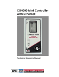
Using the Instant Mode:
1) The CS-4000 does not hang up after processing the report.
2) The CS-4000 instructs the panel to hang up and the Interrogator Module takes the line before it
is released.
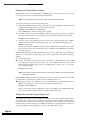
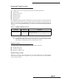
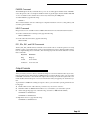
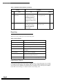
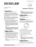
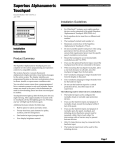
3) The CS-4000 displays “Instant Listen Mode! Line nn,” and AUDIO is shown in the CRT phone
window for line n. RS232 channels formatted to ITICOMP or GENERIC include a field, indicating instant mode, if CHANNEL n VERSION V5 is set.
PHONE WINDOW LISTS
"AUDIO" FOR THE
APPROPRIATE PHONE
LINE
DISPLAYS WHEN THE CS-4000
ENTERS INSTANT
VERIFICATION MODE
80
Alarm!
FUNCTION KEYS
ASSIGNED USING
THE "FKEYS AUDIO"
COMMAND
Figure 1. CS-4000 CRT display when using instant
verification mode on phone line 1.
4) The central station operator must pick up the handset and instruct the CS-4000 to release the
phone line. This releases the CS-4000 and establishes a connection between the handset and the
Interrogator Module. CS-4000 phone release occurs, and “LINE nn RELEASED” displays when
one of the following happens (see “Interrogator Commands” for details on each command):
• The FKEYS AUDIO command is set and the operator presses the keyboard function key, F1F4, corresponding to the line being used.
• The operator enters the HANGUP n command.
• The ATIME (05-60 seconds) set by the operator expires.
Notes:
a. The HANGUP command does not take precedence over receiving report information.
Commands are only performed after all panel reports are processed. During periods of
heavy communication, it is possible for the Interrogator Module or ATIME to time out
before the HANGUP command is performed, resulting in an error message.
b. The operator must establish a connection with the Interrogator Module before the CS4000 places the phone line on-hook. If the operator fails to pick up the handset before
the CS-4000 places the phone line on-hook, the operator may not be able to verify the
report.
5) The operator can now enter Interrogator control commands through the phone and verify the
alarm.
Page 9
CS-4000 Central Station Receiver Release Notes
Selecting Reports for Verification
The CS-4000 only selects panels for alarm verification if the panel’s report meets certain selection criteria.
To Select SX-V Reports:
1) The panel’s account number must be in the ATRAP table.
2) The report must contain an alarm, with the following exceptions:
3)
• Alarm reports for zones 0, 1, and 12-17 are ignored.
• Alarm reports for zones assigned to groups 11, 13, and 15 are ignored.
The verification mode must be set with the AUDIO command.
To Select CareTaker Plus (ver. 2) Reports:
The panel report tells the CS-4000 if the Interrogator Module is enabled and the verification mode to
use.
Notes:
a. The CS-4000 uses the verification mode specified in the panel report, not necessarily
the mode set by the AUDIO command.
b. The CS-4000 selects the panel for listen-in, regardless of whether the panel’s account
number is in the ATRAP table.
To Select Commander 2000 Reports:
1) The panel report tells the CS-4000 if the Interrogator Module is enabled.
2) The verification mode must be set with the AUDIO command.
To Select All Other Panel Reports:
1) The account number is in the ATRAP table.
2) The verification mode must be set with the AUDIO command.
Note: The panel is selected for listen-in regardless of the actual report information.
To Exclude Panel Reports from Selection:
Enter the panel’s account number into the audio exclusion table using the AEXCLUDE command,
described in “Interrogator Commands.” The panel will not be selected for listen-in, regardless of the
report content or the presence of the account number in the ATRAP table.
Interrogator Commands
The following CS-4000 commands are new with software version 5.0 and support the Interrogator
Module. The new commands are not interactive commands, with the exception of the HANGUP
command.
Page 10
CS-4000 Central Station Receiver Release Notes
ATRAP Command
Currently, the only panels that indicate the presence of an Interrogator Module to the CS-4000 are
the Commander 2000 and the CareTaker Plus (ver. 2.0.) For all other panels, the CS-4000 checks the
AUDIO TRAP (ATRAP) table to determine if an Interrogator Module is connected. This is done in
much the same way the CS-4000 checks the regular TRAP table to determine whether to release the
panel at the end of a report. The ATRAP table identifies panels with the Interrogator Module and
holds up to 100 account numbers. Table 10 summarizes the ATRAP command.
Table 10. ATRAP Command
Command
Parameters
Description
ATRAP nn-nnn
Any five letters or numbers
Assigns account number nn-nnn to the ATRAP table.
ATRAP nn-n**
Any five letters or numbers,
including * wild cards
Assigns account number nn-n** to the ATRAP table.
Wild cards assign all letters and numbers.
ATRAP nn-nnn OFF
Any five letters or numbers,
followed by OFF
Removes nn-nnn from the ATRAP table.
ATRAP ALL
ALL
Assigns account number **-*** to the ATRAP table.
ATRAP OFF
OFF
Clears the ATRAP selection table.
Notes:
a. The ATRAP command is not necessary with the Commander 2000 or CareTaker Plus
(ver. 2), which report to the CS-4000 when the Interrogator Module is enabled.
b. Unlike the TRAP table, the ATRAP table account numbers are not removed until they
are explicitly removed with the ATRAP nn-nnn OFF command.
AEXCLUDE Command
The AEXCLUDE command enters account numbers into the AEXCLUDE table. The AEXCLUDE
table holds up to ten account numbers. An entry in the AEXCLUDE table identifies account numbers to ignore when selecting reports for alarm verification, regardless of the report content or the
presence of the account number in the ATRAP table. Table 11 summarizes the AEXCLUDE command.
Table 11. AEXCLUDE Command
Command
Parameters
Description
AEXCLUDE nn-nnn
Any five letters or numbers
Assigns account number nn-nnn to the AEXCLUDE table.
AEXCLUDE nn-nnn OFF
Any five letters or numbers,
followed by OFF
Removes nn-nnn from the AEXCLUDE table.
Page 11
CS-4000 Central Station Receiver Release Notes
AUDIO Command
The AUDIO command assigns the CS-4000 alarm verification mode for Interrogator Module support. Table 12 summarizes the AUDIO command.
Table 12. AUDIO Command
Command
Parameters
AUDIO n
Description
INSTANT, DIALOUT,
ONERING, or OFF
Default
Assigns n as the CS-4000 alarm verification mode.
OFF
WARNING: All enabled Interrogator Modules must be programmed to use the same alarm verification
mode as the monitoring CS-4000, with the exception of Interrogator Modules used with the
CareTaker Plus (ver. 2), which reports the verification mode. If the verification modes are different, the operator may not be able to verify the report using the Interrogator Module.
Note: When the AUDIO OFF command is set, the CS-4000 ignores all audio verification, including
reports from CareTaker Plus (ver. 2) and Commander 2000 panels.
ATIME Command
The ATIME command assigns the maximum length of time the CS-4000 keeps a phone line off-hook
for instant mode. Refer to “Using the Instant Mode” for a complete list of ways to place the phone
line on-hook. Table 13 summarizes the ATIME command.
Table 13. ATIME Command
Command
ATIME n
Parameters
From 5 to 60
Description
Assigns n seconds for instant listen-in mode to
be initiated.
Default
30
Note: Although ATIME allows a phone line to be off-hook for up to 60 seconds, verification must be
initiated within 30 seconds when using the Interrogator Module by pressing the k button on
the central station phone used for verification.
Currently, the Interrogator Module waits 30 seconds for the operator to press the k button. If
the k button is not pressed within 30 seconds, the Interrogator Module hangs up. Consequently, setting ATIME to anything greater than 30 seconds may result in the Interrogator
Module releasing the phone line before ATIME expires. The ATIME range has a maximum of
60 seconds to allow for future enhancements to the Interrogator Module.
FKEYS Command
The FKEYS command selects the function key definition, either AUDIO or DEFAULT. With the
FKEYS AUDIO command set, the audio function key definition allows keys F1-F4 to instruct the CS4000 to hang up phone lines 1-4 respectively, when in instant verification mode. With the FKEYS
DEFAULT command set, the function key definition is the same as with all previous versions of the
software. Table 14 summarizes the FKEYS command.
Table 14. FKEYS Command
Command
FKEYS n
Page 12
Parameters
‘AUDIO’ or ‘DEFAULT’
Description
Selects n as the function key definition.
Default
DEFAULT
CS-4000 Central Station Receiver Release Notes
Table 15 lists the function key definition for AUDIO and DEFAULT.
Table 15. Function Key Definition
FKEYS
AUDIO †
DEFAULT
F1
Hang-up line 1
Line Feed
F2
Hang-up line 2
Acknowledge
F3
Hang-up line 3
Silence
F4
Hang-up line 4
Acknowledge All
F5
Line Feed
Previous Command
F6
Acknowledge
Next Command
F7
Silence
Not Used
F8
Acknowledge All
Not Used
F9
Print
Print
F10
Help
Help
† Scrolling to the previous and next command is allowed with the INSERT
and DELETE keys, respectively.
HANGUP Command
The HANGUP command places the specified phone line on-hook. The HANGUP command is summarized in the following table.
Command
Parameters
HANGUP n
1, 2, 3, or 4
Description
Default
Places phone line n on-hook, when the CS-4000 line n is in instant mode.
n/a
WARNING: The HANGUP command does not take precedence over receiving report information. During
periods of heavy communication, the HANGUP command is only performed after all panel
reports are processed. The Interrogator Module or ATIME may time out before the HANGUP
command is performed, resulting in an error message.
Input Channel Control Codes
Control codes may be sent to the CS-4000 from an external device via any of the three RS-232 channels. The version 5.0 software recognizes certain control codes that can place a telephone line onhook for instant verification mode. This works just like the HANGUP command, or keys F1-F4 with
the FKEYS AUDIO command set. These control codes can be ASCII Ctrl + letter codes or ordinary
characters, depending on the ON/OFF setting of the CHANNEL n CTRLKEYS m command. Table
16 summarizes the CHANNEL CTRLKEYS command.
Table 16. CHANNEL CTRLKEYS Command
Command
CHANNEL n CTRLKEYS m
Parameters
n from 1 to 3
m either ON or OFF
Description
Turns on or off CHANNEL n CTRLKEYS.
Default
OFF
Page 13
CS-4000 Central Station Receiver Release Notes
The following example shows the syntax of the CHANNEL CTRLKEYS command.
Example: CHANNEL n CTRLKEYS m, where n is the number of the desired RS232 channel and m is
the desired control code setting.
Table 17 shows the control codes for placing the phone line on-hook.
Table 17. Input Channel Control Codes
Function
CHANNEL
n
CTRLKEYS
OFF
CHANNEL
n
CTRLKEYS
ON
Hang-up Line 1
^D
(
Hang-up Line 2
^E
)
Hang-up Line 3
^N
<
Hang-up Line 4
^O
>
Panel Traps
When a panel is selected for Interrogator support, normal traps set with the TRAP command are
ignored for that report, allowing alarm verification. The CS-4000 displays the message “Audio
Report! Trap Ignored!” However, these account numbers remain in the TRAP table. If the panel calls
again without a verification report, the TRAP will operate normally.
Communication Locking Support for the Commander 2000
The CS-4000 software version 5.0 supports communication locking (CommLock) for the Commander 2000. CommLock enables a dealer to ensure that customer accounts are not lost to another
monitoring service. CommLock offers two independent locking methods:
Phone Lock
Central Station Lock
Note: A panel can operate without a locking method, or with either locking method; however, a
panel cannot use both methods simultaneously. If the panel’s dealer programming code is not
the default, the CS-4000 will not enable Central Station Lock for that panel. If the panel’s
security code is not the default, the panel will not allow changes to the dealer programming
code and will only communicate with the CS-4000 with the matching security code. The CS4000 will continue to communicate with older panels as in the past.
WARNING: Erasing panel memory does not reset CommLock. Other than using the methods provided to
remove a lock, normal panel access can only be restored and CommLock can only be reset
by sending the panel to ITI for repair.
WARNING: Communication Locking is a powerful feature. Misuse can result in the loss of report monitoring for communicating panels.
Page 14
CS-4000 Central Station Receiver Release Notes
Phone Lock
The Commander 2000 has two programming codes that allow entry into local program mode from a
touchpad. The dealer programming code allows the dealer to change all programmable values. The
installer programming code allows the installer to change all values, except the dealer programming
code and the primary phone number.
When the installer code is used, the dealer programming code and the primary phone number are
protected, and the installer can perform all other panel programming.
WARNING: When Phone Lock is used, the primary phone number and dealer programming code can
only be changed using the dealer programming code.
WARNING: Phone Lock is a powerful feature. Misuse can result in the loss of report monitoring for communicating panels.
Protection at the Panel
The dealer programming code can be changed from its default to any sequence of four digits.
Changing the dealer programming code requires the new code to be entered twice.
If the two codes are not entered exactly the same, the panel indicates that the entered code is incorrect, and the programming code is not changed. This procedure prevents any inadvertent programming code changes. Refer to the panel’s reference manual for instructions on changing dealer
programming code.
Protection at the CS-4000
The PLOCK command allows the CS-4000 operator to change the panel’s dealer programming code,
if the current code is known. The following example shows the command necessary to change
dealer programming code 4321 to 8765 from the CS-4000.
Example: PLOCK 4321 %87658765
The CS-4000 handles the new code the same way as operator passwords. The new code must be preceded by a % symbol, which causes the CS-4000 to mask the code input with *. The dealer programming code is never displayed or printed. The CS-4000 displays “CPU Dealer Programming Code
Changed” when the command is entered correctly.
Phone Lock is removed by programming the dealer programming code to the default code of 4321.
Table 18 summarizes the PLOCK command.
Note: The PLOCK command does not work on panels already using Central Station Lock.
Table 18. PLOCK Command
Command
PLOCK aaaa %nnnnnnnn
Parameters
Any four numbers,
repeated.
Description
Assigns nnnn to the dealer programming code, which
was aaaa.
Default
4321
Central Station Lock
When a CS-4000 communicates with a panel, the CS-4000 must send a valid security code before the
panel will report. Central Station Lock allows the CS-4000 operator to define a primary security code
to be used in the reporting sequence. Once the primary security code is set, the CS-4000 may be
instructed to update reporting panels to respond to this code instead of the default security code.
The CS-4000 maintains a table of panel accounts for security code updates. The CS-4000 uses this
table to select reporting panels for automatic security code updates.
Page 15
CS-4000 Central Station Receiver Release Notes
Once updated, panels require the primary security code from the CS-4000 before they will report. If
the CS-4000 sends the wrong security code, the panel and CS-4000 hang up. The CS-4000 displays
“Improper Security Code,” as well as the panel account information.
Note: The CS-4000 will always communicate with panels using the default security code and will
continue to communicate with older panels as in the past.
WARNING: Central Station Lock features must be used with care. Misuse can result in the loss of panel
communication with the CS-4000. Security codes are never displayed, so it is critical to prevent unintentional code changes. As a precaution, write down all security codes and maintain the list in a safe location.
WARNING: Central Station Lock is a powerful feature. Misuse can result in the loss of report monitoring
for communicating panels.
Using Central Station Lock:
1) Define the CS-4000’s primary security code using the CSLOCK DEFINE command.
2) Select a security code update mode with one of the following commands:
• CSLOCK SET instructs the CS-4000 to set the selected panels to the primary security code.
• CSLOCK REMOVE instructs the CS-4000 to remove the primary codes from the selected panels and set the panel to the default security code.
• CSLOCK OFF prevents the CS-4000 from updating the security code of reporting panels.
Notes:
a. CSLOCK can only be set to one mode at a time: SET, REMOVE, or OFF. The CS-4000
cannot simultaneously update some panels to accept the primary security code
(CSLOCK SET), and others to accept the default security code (CSLOCK REMOVE).
b. Panels can communicate to a CS-4000 if:
• The Panel’s CSLOCK is off (default).
• The Panel’s Security Code matches the CS-4000 Primary Security Code.
• The Panel’s Security Code matches a code in the CS-4000 SCODE Table.
3) Select panel account numbers for security code updates, using the CSLOCK SELECT command.
Note: If the security code update mode is set to CSLOCK OFF, panels selected with CSLOCK
SELECT will not be updated. CSLOCK OFF disables the security code update so it is not
necessary to remove all the accounts from the selection table.
WARNING: The CSLOCK RESET OKAY command resets the CS-4000’s primary security code. Panels
using the old code can no longer report to the CS-4000.
Using the CSLOCK Command
The CSLOCK command is a receiver configuration command. Entered once at the CS-4000, it
remains in effect until another command resets the instruction. CSLOCK command instructions are
automatically followed every time a report is made to the CS-4000.
WARNING: CSLOCK is a powerful command. Misuse can result in the loss of report monitoring for communicating panels.
Page 16
CS-4000 Central Station Receiver Release Notes
Table 19 shows how to use the CSLOCK command to:
Define the CS-4000’s primary security code.
Select panel account numbers for security code updates.
Reset the CS-4000 Central Station Lock configuration.
Table 19. CSLOCK Command
Command
Parameters
Description
CSLOCK DEFINE %nnnnnnnnnn
Any five numbers
or letters, repeated.
Defines nnnnn as the CS-4000’s primary security code.
CSLOCK SELECT nn-nnn
Any five numbers,
including * wildcards.
Selects account number nn-nnn for security code updates.
The CSLOCK selection table holds up to 25 different
account numbers.
ALL
Selects all accounts for security code updates.
OFF
Clears the CSLOCK table, and selects 00-000.
Note: The primary security code must be entered twice, with no spaces, for the CSLOCK DEFINE
command. The % character instructs the CS-4000 to mask the code on the CS-4000 display
or when printed.
Error messages display and no changes are made when using the CSLOCK DEFINE command and:
• The new Primary Security Code is not entered correctly twice.
• The security code already exists in the SCODE Table.
• The security code is the default code.
Selecting a Security Code Update Mode
Table 20 shows how the CSLOCK command is used to select the security code update mode.
Note: The security code update mode can only be set to one mode at a time: SET, REMOVE, or
OFF.
Table 20. CSLOCK Command for Selecting the Security Code Update Mode
Command
CSLOCK
CSLOCK RESET OKAY
†
†
Parameters
Description
SET
Places the CS-4000 in a mode that updates reporting panels with the primary
security code, enabling Central Station Lock for those panels.
REMOVE
Places the CS-4000 in a mode that updates reporting panels with the default
security code, disabling Central Station Lock for those panels.
OFF
The CS-4000 sends the appropriate security code, but will not update the
panel’s code.
n/a
Resets the CS-4000’s primary security code to the default and places the CS4000 in CSLOCK OFF mode.
This command resets the CS-4000 Central Station Lock configuration and the CS-4000’s primary security code to its default. Panels using the old
code can no longer report to the CS-4000.
Page 17
CS-4000 Central Station Receiver Release Notes
Examples of Central Station Locking
Scenario One: You have just completed the CS-4000 upgrade to version 5.0 software, and you wish
to use central station lock on all panels that support the feature.
Note: The Commander 2000 is the only panel that currently supports CommLock.
To configure central station lock on all reporting panels:
1) Define the CS-4000’s primary security code, using the CSLOCK DEFINE command. For this
example, we will define the primary security code as ABCDE.
Example: CSLOCK DEFINE %ABCDEABCDE
The CS-4000 displays “Primary Security Code Changed!”
2) Select the accounts you want the CS-4000 to update with the primary security code, ABCDE.
The scenario calls for all panels to be included, so use the CSLOCK SELECT ALL command.
Example: CSLOCK SELECT ALL
3) Select the security code update mode. The CSLOCK SET command instructs the CS-4000 to
update all selected panels from the default security code to ABCDE, when the panels report.
Example: CSLOCK SET
When a panel calls the CS-4000 with any report, the CS-4000 automatically updates the selected
panel’s security code to the code defined in step 1, ABCDE. The CS-4000 displays “Updating
CS-LOCK for Panel.”
Scenario Two: Building on the steps performed in scenario one, two panels have reported and been
updated to use the primary security code, and you wish to prevent any other panels from being
updated.
To prevent locking panels:
Change the security code update mode. The CSLOCK OFF command prevents the CS-4000
from updating the reporting panel’s security code. The CS-4000 will still accept reports from
panels using the default security code, the CS-4000’s primary security code, or any security
code in the SCODE table.
Example: CSLOCK OFF
Note: The CS-4000 continues to send the primary security code, ABCDE, to the panels that have
already been updated.
Scenario Three: Building on the steps performed in scenario one and two, you wish to remove the
lock from the two panels that were updated to use the ABCDE security code.
Change the security code update mode. The CSLOCK REMOVE command instructs the CS4000 to remove the panel’s security code and set it back to the default code.
Example: CSLOCK REMOVE
When a panel reports to the CS-4000 using security code ABCDE, the CS-4000 automatically
removes the code and sets the panel back to use the default security code.
Adding Accounts with Central Station Lock
The SCODE command allows the CS-4000 to use different security codes with the Central Station
Lock feature. This command may be used when you take on another CS-4000’s accounts, and the
panels already have security codes assigned for Central Station Lock. These panels will receive an
invalid security code when calling your CS-4000; consequently, no report will be made. For this reason, the SCODE table exists to keep track of security codes used by these panels.
Page 18
CS-4000 Central Station Receiver Release Notes
Managing the SCODE Table:
1) Add security code n to the SCODE table with the SCODE ADD n command.
2) Add security code n to the SCODE table and enable the CS-4000 to update the security codes of
panels using this code with the SCODE UPDATE n command.
Note: The SCODE UPDATE command is subject to the CS4000’s security code update mode,
which is enabled with the CSLOCK command. If CSLOCK SET is enabled, the panel’s security code is updated to the CS-4000’s primary security code. If CSLOCK REMOVE is enabled,
the panel’s security code is updated to the default security code. If CSLOCK OFF is enabled,
the panel’s security code is not updated.
3) Remove security code n from the SCODE table with the SCODE OFF n command.
WARNING: Security codes maintained in the SCODE table cannot be displayed or printed. As a precaution, write down all security codes and maintain the list in a safe location.
Using the SCODE Command
Table 21 summarizes the SCODE command, which is used to manage the SCODE table. The SCODE
table holds up to 25 security codes, unique form the CS-4000’s primary security code, and the
default security code.
Table 21. SCODE Command
Command
Parameters
Description
SCODE ADD %nnnnnnnnnn
Any five numbers
and letters, repeated.
Adds security code nnnnn to the SCODE table, without
allowing the CS-4000 to update the panel’s security code.
SCODE UPDATE %nnnnnnnnnn
Any five numbers
and letters, repeated.
Adds security code nnnnn to the SCODE table and allows
the CS-4000 to update the panels using this code.
SCODE OFF %nnnnnnnnnn
Any five numbers
and letters, repeated.
Removes the security code nnnnn from the SCODE table.
n/a
Removes all security codes from the SCODE table.
SCODE RESET OKAY
†
†This command removes all security codes from the SCODE table.
Example of Using the SCODE Command
Scenario Four: Building on the steps performed in “Example of Central Station Locking,” your central station is taking on some new accounts that were previously monitored by a different CS-4000
that was using the central station lock feature. The panels were assigned the security code GAFER
by the other CS-4000, and you want to update them to use your CS-4000’s primary security code.
To update a new security code:
Add the new security code, GAFER, to the SCODE table. The SCODE UPDATE command
allows you to add a security code to the SCODE table and instructs the CS-4000 to update panels using this code.
Example: SCODE UPDATE %GAFERGAFER
When a panel using the security code GAFER reports, and the CS-4000’s security code update
mode is SET, the CS-4000 automatically updates the panel’s security code to ABCDE, the CS4000’s primary security code. If the security code update mode is REMOVE, the panel’s security
code is automatically removed and the code is updated to the default.
Page 19
CS-4000 Central Station Receiver Release Notes
Scenario Five: Building on the steps performed in scenario four, your central station is also taking
on other accounts. The new accounts have the security code BRETT and do not want it changed.
To add a new security code:
Add the new security code, BRETT, to the SCODE table. The SCODE ADD command allows
you to add a security code to the SCODE table and instructs the CS-4000 not to update panels
using this security code.
Example: SCODE ADD %BRETTBRETT
When a panel using the security code BRETT reports, the CS-4000 receives the report, but will
not change the panel’s security code.
Checking the CommLock Configuration
The CS-4000 operator can check the CS-4000’s CommLock configuration with the following commands.
CSLOCK Command
The CSLOCK command displays the current security code update mode as one of the following:
CSLOCK mode is SET.
CSLOCK mode is REMOVE.
CSLOCK mode is OFF.
CSLOCK SELECT Command
The CSLOCK SELECT command displays the CSLOCK select table, which is the table of accounts
selected for security code updates.
CPUTYPE ON Command
The CPUTYPE ON command has been enhanced to display the CommLock method being used by a
reporting panel. When a panel supporting the CommLock feature reports, the CS-4000 displays one
of the following:
CPU is using Phone-Lock.
CPU is using CS-Lock.
CPU is not using CommLock.
MSTAT Command
The MSTAT command has been enhanced to display the security code update mode.
STAT Command
The STAT command has been enhanced to display the security code update mode.
Page 20
CS-4000 Central Station Receiver Release Notes
Expanded Output Formats
The CS-4000 software version 5.0 supports the following expanded output formats:
Generic Format
Ademco/CAPS Format
ITICOMP Format
Honeywell Format
Radionics Format
Suplow Format
The CHANNEL command has been modified with a new option that allows selection between the
new enhanced channel output codes and output codes that are similar to those supported by CS4000 version 4.0 software. The CHANNEL command now has the VERSION option, which can be
set to V4 or V5. The default VERSION setting is V5. Table 22 summarizes the CHANNEL VERSION
command.
Table 22. CHANNEL VERSION Command
Command
CHANNEL n VERSION m
Parameters
n = 1,2, or 3
m either V4 or V5
Description
V5 configures all new output report codes for the CS-4000 software
version 5.0 enhancements.
V4 configures output codes similar to the CS-4000 software version
4.0 output codes.
Note: The CHANNEL n VERSION m command setting determines the output codes for Generic,
ITICOMP, and Suplow output formats. For this reason, the output code changes listed for
these formats in the following sections are marked as either V4 or V5.
Generic Format
The Generic format output has been modified to accommodate the following:
Modified output codes
COMPLOG command
Interrogator condition codes
Modified Output Codes
Table 23 shows changes to the Generic format for V4 and V5 output codes. For complete details
about the Generic format, refer to Appendix A in your CS-4000 Central Station Receiver Installation
and User’s Manual (46-056).
Page 21
CS-4000 Central Station Receiver Release Notes
Table 23. Generic Format Changes Supported by V4 and V5 Output Codes
Generic Output Byte
CS-4000
Message
Name
†
Low Battery Unit n ‡
CPU Shut Down ¥
Auto Event Dump ¥
Unit ID
Trouble
Supervisory Unit n
Improper Security Code
¥ƒ
Number
10
CHANNEL
VERSION
Code
0-9
V4 and V5
0-9
V4 and V5
Condition code
13
S
V4 and V5
Condition code
13
A
V4 and V5
Condition code
13
L
V4
J
V5
I
V5
Condition code
13
No output record is sent.
V4
Alarm Buddy System n
Buddy number
10
1-4
V4 and V5
Phone Test (E31, E3x, E41,
E42 commands)
Condition code
13
A
V4
P
V5
† This message includes buddy, touchpad, and hardwire unit supervisory reports.
‡ This message is for touchpad low battery reports.
¥ This message is new with version 5.0 software. Refer to “Reporting from the Commander 2000” for more information on these
messages.
ƒ The zone byte is set to zero, no zone information is reported to the CS-4000.
Table 24 shows additional changes to the Generic Format for V4 and V5 output codes.
Table 24. Generic Format Changes Supported by V4 and V5 Output Codes
CS-4000 Report Record
Information
User ID
Group number
Page 22
Range
0-9
Generic Output Byte
Use
V4 and V5
10 - 35
A-Z
V4 and V5
36 - 61
a-z
V4 and V5
62 and
greater
?
V4 and V5
0-9
V4 and V5
10 - 35
A-Z
V4 and V5
36 - 61
a-z
V4 and V5
Group number
10
Code
0-9
0-9
User ID for openings and closings
Number
CHANNEL
VERSION
9
CS-4000 Central Station Receiver Release Notes
COMPLOG command
The COMPLOG command enables the CS-4000 to include a phone log record at the beginning and
end of each call. With COMPLOG ON, a string of reports generated by a call is encapsulated within
two phone log records, one at the beginning and one at the end of the group of reports. The following table summarizes the COMPLOG command.
Command
Parameters
COMPLOG nnn
Description
ON or OFF
Default
Turns ON or OFF phone log records at beginning and end of reports.
ON
Table 25 shows the byte arrangement of the phone log record.
Table 25. Phone Log Record Format
Byte
Parameters
Description
0
LF
ASCII line feed
1
0-9
Receiver ID (RID command)
2
1-4
Phone line number
3
0-9
Report event sequence (1 of 4)
4
0-9
Report event sequence (2 of 4)
5
0-9
Report event sequence (3 of 4)
6
0-9
Report event sequence (4 of 4)
7
0
Constant
8
0
Constant
9
0
Constant
10
0
Constant
11
0
Constant
12
0
Constant
13
F, N
Condition code
14
CR
ASCII carriage return
Table 26 provides an example of a report record encapsulated within two phone log records.
Table 26. Generic Format Report Record Encapsulated within Phone Log Records
Record Byte Numbers
Record
0
1
2
3
4
5
6
7
8
Phone Log
LF
1
1
2
3
4
5
0
0
Report
LF
1
1
A
X
B
C
D
Phone Log
LF
1
1
2
3
4
5
0
9
10
11
12
13
14
0
0
0
0
N
†
CR
E
5
0
1
1
A
0
0
0
0
0
F
CR
†
CR
LF: line feed
CR: carriage return
† Byte 13 of the phone log record marks the start and end of reporting with N and F respectively.
Page 23
CS-4000 Central Station Receiver Release Notes
Interrogator Condition Codes
The Generic format uses three new condition codes to indicate the alarm verification mode used for
Interrogator support. Byte 13, condition code, normally contains an A for alarm reports.
Notes:
a. The three new codes only substitute for an A code.
b. The three new codes are not used if AUDIO is set to OFF.
c. The three new codes are not used if the CHANNEL n VERSION V4 command is set.
Table 27 shows the four possible condition codes that report the alarm verification mode.
Table 27. Generic Format Interrogator Condition Code Output
Condition
Code
Verification
Mode
Example
Output Record
A
none
02CpTPL20001A
V
Instant
02CpTPL20001V
D
Dialout
02CpTPL20001D
G
One-ring
02CpTPL20001G
Ademco/CAPS Format
The Ademco format has been modified for Commander 2000 pseudo zone numbering and reports.
Changes to Commander 2000 Pseudo Zone Numbering
The three-digit pseudo zones that report under special conditions have been changed to accommodate the zone numbers now available with the Commander 2000. The zone number changes are the
same as those previously made for the CareTaker Plus. Table 28 summarizes the pseudo zone number changes.
Table 28. Commander 2000 Pseudo Zone Number Changes
Pseudo Zones †
Commander
2000 Pseudo
Zones
018 exit fault
218 exit fault
028 supervisory
228 supervisory
038 low battery
238 low battery
† The original pseudo zone numbers are still used for
other panel types.
Page 24
CS-4000 Central Station Receiver Release Notes
New Commander 2000 Reports
Table 29 summarizes the output characters generated by the new Commander 2000 reports.
Table 29. Ademco Output for New Commander 2000 Reports
CS-4000 Message
Ademco
Output
CPU Shut Down
A
Auto Event Dump
A
ITICOMP Format
The ITICOMP format output has been changed to accommodate the following enhancements:
•
•
•
Modified output codes
CommLock support
Interrogator support
Modified Output Codes
Table 30 summarizes the changes that have been made to the ITICOMP output format for V4 and V5
output codes.
Table 30. ITICOMP Format Changes Supported by V4 And V5
ITICOMP Output
CS-4000 Message
Name
Field
Code
CHANNEL
VERSION
†
Low Battery Unit x ‡
CPU Shut Down ¥
Auto Event Dump ¥
Subunit ID
|S
0-9
V4 and V5
Condition Code
|C
S
V4 and V5
Condition Code
|C
A
V4 and V5
Trouble
Condition Code
|C
L
V4
|C
J
V5
Condition Code
|C
Z
V4 and V5
Condition Code
|C
I
V5
Supervisory Unit x
Phone Test (E31, E3x, E41, E42
commands)
Improper Security Code
¥ƒ
No output record is generated.
Alarm Buddy System n
Buddy Number
|S
V4
1-4
V4 and V5
† This message includes buddy, touchpad, and hardwire unit supervisory reports.
‡ This message is for touchpad low battery reports.
¥ This message is new with version 5.0 software. Refer to “Reporting from the Commander 2000” for more information on these messages.
ƒ The zone field is not included in the output record, no zone information is reported to the CS-4000.
Page 25
CS-4000 Central Station Receiver Release Notes
CommLock Support
The following changes have been made to the ITICOMP output format for V5 output codes.
The new Phone Lock report, “Improper Security Code,” uses condition code I.
Note: The zone field |Z is not included in the output record because no zone information is reported
to the CS-4000.
The [R record type includes the new |O field. This field contains a single digit corresponding to
the CommLock method used for reporting panels. Table 31 shows the possible field values,
their descriptions, and examples.
Table 31. ITICOMP Format CommLock Method Output
O Field
Locking Method
Example
1
Phone Lock Method
|[R|IA0|O1|L2|AC2000|P11|VT6000|G00|D0317|T1539|N3|Z1|CA|]
2
CS Lock Method
|[R|IA0|O2|L2|AC2000|P11|VT6000|G00|D0317|T1542|N4|Z1|CA|]
3
No Method in use
|[R|IA0|O3|L2|AC2000|P11|VT6000|G00|D0317|T1545|N5|Z1|CA|]
Interrogator Support
The following change has been made to the ITICOMP output format when CHANNEL n VERSION
V5 is set.
The [R record type includes the new |M field. This field contains a single digit representing the
alarm verification mode being used for the report. Table 32 shows the possible field values, their
descriptions, and examples.
Table 32. ITICOMP Format Verification Mode Output
M Field
†
Verification
Mode
Example
0
none
|[R|IA0|M0|L2|ACTPL2|P11|VT4200|G00|D0317|T1539|N3|Z1|CA|]
1
Instant Mode
|[R|IA0|M1|L2|ACTPL2|P11|VT4200|G00|D0317|T1539|N3|Z1|CA|]
2
Dialout Mode
|[R|IA0|M2|L2|ACTPL2|P11|VT4200|G00|D0317|T1542|N3|Z1|CA|]
3
One-Ring Mode
|[R|IA0|M3|L2|ACTPL2|P11|VT4200|G00|D0317|T1545|N3|Z1|CA|]
† No |M field is included if the AUDIO OFF command is set.
Page 26
CS-4000 Central Station Receiver Release Notes
Honeywell Format
The Honeywell format has been changed to accommodate modified output codes.
Modified Output Codes
Table 33 summarizes the changes that have been made to the Honeywell output format for CS-4000
reports.
Table 33. Honeywell Output Format Changes for New CS-4000 Reports
Honeywell Code
CS-4000 Report
Previous
Current
Low MCU Battery
n/a
T9
CPU Low Battery Restoral
T9
R9
n/a
R9
n/a
T9
n/a
R9
Auto Event Dump
†
Improper Security Code!
†
non-ITI phone test (e31, e3x,
e41, e42 commands)
† Commander 2000 reports.
Table 34 summarizes the changes that have been made to the Honeywell output format for CS-4000
sensor groups.
Table 34. Honeywell Output Format Changes for CS-4000 Sensor Groups
CS-4000
Honeywell Code
Panel
Group
29
43
44
Type
AUXILIARY
Environmental
FIRE
Previous
Current
CareTaker Plus
n/a
A8
Commander 2000
n/a
A8
CareTaker Plus
n/a
T9
Commander 2000
n/a
T9
CareTaker Plus
A
A1
Commander 2000
n/a
A1
Page 27
CS-4000 Central Station Receiver Release Notes
Radionics Format
The Radionics Format has been changed to accommodate modified output codes.
Modified Output Codes
Table 35 summarizes the changes that have been made to the Radionics output format for specific
CS-4000 reports.
Table 35. Radionics Output Format Changes for CS-4000 Reports
Radionics Code
CS-4000
Report
Previous
Current
Low MCU Battery
n/a
T9
CPU Low Battery Restoral
T9
R9
n/a
R9
n/a
T9
n/a
R9
†
Auto Event Dump
Improper Security Code!
†
non-ITI phone test (e31, e3x,
e41, e42 commands)
† Commander 2000 reports.
Table 36 summarizes the changes that have been made to the Radionics output format for specific
group numbers assigned to sensors.
Table 36. Radionics Output Format Changes for CS-4000 Sensor Groups
CS-4000
Radionics Code
Panel
Group
44
43
29
Page 28
Type
FIRE
Environmental
AUXILIARY
Previous
Current
CareTaker Plus
A
A1
Commander 2000
n/a
A1
CareTaker Plus
n/a
T9
Commander 2000
n/a
T9
CareTaker Plus
n/a
A8
Commander 2000
n/a
A8
CS-4000 Central Station Receiver Release Notes
Suplow Format
The Suplow Format has been changed to accommodate modified output codes.
Modified Output Codes
Table 37 summarizes the changes that have been made to the Suplow output for CHANNEL n VERSION V4 and V5.
Table 37. Suplow Format Changes
CS-4000 Message
Trouble message
Suplow
Output
Code
CHANNEL
VERSION
LB
V4
TR
V5
Supervisory Unit
SP
V4 and V5
Low Battery Unit
LB
V4 and V5
Low MCU Battery
LB
V4 and V5
Page 29
CS-4000 Central Station Receiver Release Notes
Page 30
CS-4000 Release Notes
CS-4000 Central Station Receiver Release Notes
Document Number: 46-700 Rev. H
November 1997
Appendix O: CS-4000 Software Release 5.3
About This Document
This document describes CS-4000 enhancements made in the CS-4000 Extended Memory Module
software version 5.3 (80-141). This version provides support for the SX-V Special (60-324) and Security Pro (60-637) Control Panels. Instructions for using the new printer, the Okidata MicroLine 184,
are also included. Refer to the CS-4000 Installation and User’s Manual (46-056) and the appropriate
control panel installation manuals for more details.
WARNING: Before installing this software, perform an MSTATUS command to obtain a printout of the CS4000’s current settings. If you are using the E31, E3X, E41, or E42 commands, obtain a printout
of their settings also.
Note:
Software version 5.3 will not work on a CS-4000 that does not have 64K of random-access memory (RAM). Make sure your CS-4000 is part number 60-197-64K before attempting to install this
software. If you do not have 64K, contact ITI Order Processing at 1-800-777-4841 for an upgrade.
Overview
The CS-4000 software version 5.3 includes the following:
New panels, SX-V Special and Security Pro 4000
New printer, the Okidata MicroLine 184
New reports for existing panels
New receiver and interactive commands
Modified receiver commands new panels
New Panels
Two new panels, the SX-V Special and the Security Pro 4000, are supported in this release.
SX-V Special
Please refer to the SX-V Special Panel Release Notes (46-905) for more information.
SX-V Special Commands
Commands for programming the SX-V Special are the same as those used for the SX-V. The following commands are new for the SX-V Special.
Page 1
CS-4000 Central Station Receiver Release Notes
KEY Command
The KEY command sets the arm/disarm levels for the optional, two-position key-switch control. To
use this command, type the following:
KEY N X
Replace the N with the arming level (0-7), and X with the disarm level (0-7).
Display KEY Command
To see the KEY command appear in the list of receiver commands, use the DISPLAY SXVSP ON/
OFF command.
To include the KEY command in the commands list, type the following:
DISPLAY SXVSP ON
The next time you display the list of commands, it includes the KEY command.
To remove the KEY command from the command list, type the following:
DISPLAY SXVSP OFF
The next time you display the list of commands, the KEY command will not be listed.
SX-V Special Reports
Verify that your automation package correctly interprets installer defined zones 00-99 and upper
sensor numbers 100-119.
Sensor Reports (sensor N: 0-99)
N Alarm!
N Canceled
N Alarm! Tamper!
N Exit Fault
N Supervisory
N Low Battery
N Bypassed
Upper Sensor Reports (sensor N: 100-119)
Page 2
100 Alarm! Buddy System! N (N: 1-4)
107 Opening Report User N (N: 0-9, A-Z)
100 Supervisory Unit N (N: 1-4)
108 Closing Report User N (N: 0-9, A-Z)
101 Alarm! Touchpad Tamper!
109 Alarm! Silent DURESS!
102 Supervisory Unit N (N: 0-7)
110 Force Armed
103 Alarm! Manual Fire!
111 A/C Power Failure
104 Alarm! Manual Police!
111 A/C Power Restored
105 Alarm! Manual Medical!
112 Low CPU Battery
106 Phone Test
112 Power Supply Failure
CS-4000 Central Station Receiver Release Notes
Upper Sensor Reports (sensor N: 100-119)
112 Alarm Restoral
115 Receiver Failure!
113 Alarm! Tamper Loop!
116 CPU Back in Service
113 Alarm Restoral
119 Low Battery Unit N (N: 0-14)
114 Automatic Phone Test
119 Program Change
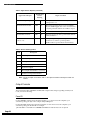
Generic Output for SX-V Special Panel
The SX-V Special Panel can have up to 99 RF sensors. The upper sensor numbers range from 100 to
119. This means that an alarm for sensor number 83 could send the same code as a traditional upper
sensor. For example, an SX-V phone test (zone 83) is reported as 83A (zone 83 alarm). For the SX-V
Special, an 83 alarm is a sensor alarm.
The panel type can be used to identify the actual report message so that 83A is interpreted differently for SX-V and SX-V Special panels. The panel account data and/or panel ID data, provided in
the RS-232 output record, can be used to determine the panel type. With GENERIC XID on, byte 4 of
the output record (r) indicates the SX-V Special panel type.
(Refer to the “New Receiver Commands” section of this document for information on the GENERIC
XID command.)
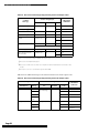
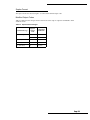
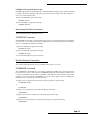
Examples
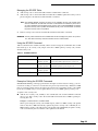
Table 1 lists the SX-V Special reports and Generic output records. The examples use 12345 as the
reported account number.
Page 3
CS-4000 Central Station Receiver Release Notes
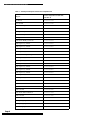
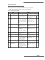
Table 1. SX-V Special Reports and Generic Output Record
Page 4
Report
Generic Output Record (XID ON)
NODATA 20
99 Alarm!
041r23454 99A
99 Canceled
041r23454 99R
99 Alarm! Tamper!
041r23454 99T
99 Exit Fault
041r23454 99E
99 Supervisory
041r23454 99S
99 Low Battery
041r23454 99L
99 Bypassed
041r23453 99B
100 Alarm! Buddy System! 01
041r2345C1A0A
100 Supervisory Unit 01
041r2345C1A0S
100 Supervisory Unit 02
041r2345C2A0S
100 Supervisory Unit 03
041r2345C3A0S
100 Supervisory Unit 04
041r2345C4A0S
101 Alarm! Touchpad Tamper!
041r2345D A1A
102 Supervisory Unit 00
041r2345E0A2S
102 Supervisory Unit 01
041r2345E1A2S
102 Supervisory Unit 02
041r2345E2A2S
102 Supervisory Unit 03
041r2345E3A2S
102 Supervisory Unit 04
041r2345E4A2S
102 Supervisory Unit 05
041r2345E5A2S
102 Supervisory Unit 06
041r2345E6A2S
102 Supervisory Unit 07
041r2345E7A2S
103 Alarm! Manual Fire!
041r2345A A3A
103 Canceled
041r2345A A3R
104 Alarm! Manual Police!
041r2345A A4A
104 Canceled
041r2345A A4R
105 Alarm! Manual Medical!
041r23451 A5A
105 Canceled
041r23450 A5R
106 Phone Test
041r2345D A6A
107 Opening Report User 0
041r2345D0A7A
107 Opening Report User 1
041r234511A7A
108 Closing Report User 0
041r2345D0A8A
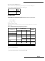
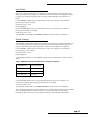
CS-4000 Central Station Receiver Release Notes
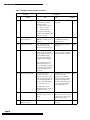
Table 1. SX-V Special Reports and Generic Output Record
Report
Generic Output Record (XID ON)
NODATA 20
108 Closing Report User F
041r2345D A8A
109 Alarm! Silent Duress!
041r2345D A9A
110 Force Armed 0
041r2345D C0A
111 A/C Power Failure
041r2345E C1A
111 A/C Power Restored
041r2345E C1S
112 Low Panel Battery
041r2345E C2A
113 Alarm! Tamper Loop!
041r23452 C3A
113 Alarm Restoral
041r23452 C3W
113 Canceled
041r23452 C3R
114 Automatic Phone Test
041r2345E C4A
115 Receiver Failure!
041r2345D C5S
116 Panel Back In Service
041r2345D C6A
119 Low Battery Unit 00
041r2345D0C9L
119 Program Change
041r2345D C9A
Security Pro 4000 Panel
A new panel, the Security Pro 4000, is a special 40-zone version of the CareTaker® Plus Panel (60435). All of the panel’s reports, outputs, and programming commands are similar to the CareTaker
Plus Panel.
New Printer Okidata MicroLine 184
The Okidata MicroLine 184 printer replaces the Epson LX-810 printer, which was discontinued by
the manufacturer. This printer and associated ITI surge protector have been approved for use with
the CS-4000 by Underwriters Laboratory (UL). We recommend replacing the Epson printer with the
Okidata printer.
Refer to these part numbers when ordering printers and surge protectors.
Okidata MicroLine 184 (ITI part# 13-352)
Surge protector (ITI part# 13-227)
Printer Emulation
The Okidata MicroLine 184 printer comes with either IBM emulation or STANDARD emulation.
You MUST use the Okidata MicroLine printer 184 with STANDARD emulation. If you order the
printer from ITI, you will receive a STANDARD emulation printer. If you order the printer somewhere else, order an Okidata MicroLine 184 - Okidata part# 6240-9701 to receive a STANDARD
emulation printer.
Page 5
CS-4000 Central Station Receiver Release Notes
To verify your printer has the correct emulation, you can run a printer self-test. To do this, hold
down the line feed button and turn on the printer. The first line of the test should read: ML184
TURBO STD for STANDARD emulation.
CS-4000 Configuration
When you power up the CS-4000, channel 1 defaults to the Okidata printer format instead of Epson.
If you are using another printer, you will have to type an additional command at power-up to reconfigure the channel. This is a configuration command; you only have to enter it once.
To configure the CS-4000 for the Epson LX-810, type the following:
CHANNNEL 1 FORMAT EPSON
After you purchase an Okidata printer, type the following:
CHANNEL 1 FORMAT OKIDATA
Printer Configuration
The CS-4000 Channel 1 is intended to be used with the Okidata printer. The default settings for the
channel are 1200 baud, wordsize 7, parity even, stopbits 2. The following details how to configure
the Okidata MicroLine 184 printer for these settings.
DIP Switch Settings
The Okidata MicroLine 184 printer has two banks of DIP switches on the serial interface board as
shown in Figure 1.
SERIAL
INTERFACE
BOARD
DIP
SWITCH
LOCATIONS
SW2
(DIP SWITCH
BANK 2)
SW1
(DIP SWITCH
BANK 1)
SWITCH
COVER
1004G12A.DS4
Figure 1. Okidata MicroLine 184 DIP Switch Location
Page 6
CS-4000 Central Station Receiver Release Notes
To use the Okidata MicroLine 184 with the CS-4000 (the CS-4000 with default settings), you must set
the printer’s DIP switches from the factory default settings to the CS-4000 printer settings using the
following tables.
Table 2 shows how to change the factory default settings to the CS-4000 printer settings on DIP
switch bank 1.
Table 2. DIP Switch Bank 1 on the Serial Interface Board
Change
DIP Switch
Number:
From
Factory Default
Setting:
To
CS-4000 Printer
Setting:
1
ON
OFF
2
ON
OFF
3
ON
OFF
4
ON
OFF
5
ON
ON
6
ON
ON
7
OFF
ON
8
ON
ON
Table 3 shows how to change the factory default settings to the CS-4000 printer settings on DIP
switch bank 2.
Table 3. DIP Switch Bank 2 on the Serial Interface Board
Change
DIP Switch
Number:
From
Factory Default
Setting:
To
CS-4000 Printer
Setting:
1
OFF
ON
2
ON
ON
3
ON
OFF
4
ON
OFF
5
ON
ON
6
ON
ON
7
ON
ON
8
(NOT USED)
(NOT USED)
UL Installations
Refer to Appendix F for details.
Keyboard:
The CS-4000 keyboard is a personal computer-style keyboard. (UL
requires that the Maxiswitch Inc. Part Number 2186002A, 2189001-00411, or 2192004-xx-xxx be used.)
AC Power Connection:
Connect the 115 VAC power cord to the receptacle on the back of the
receiver.
Page 7
CS-4000 Central Station Receiver Release Notes
New Report for Existing Panels
Panels now send keychain reports.
Keychain Touchpad
The Keychain Touchpad (60-606, 4 button; 60-607, 2 button) permits customers to arm and disarm
their alarm panels with a keychain-sized device. This product can be used with CareTaker Plus (version 3.0), Security Pro 4000, and Commander® 2000 (version 4.0) (60-437) panels.
Each keychain can be used as either a sensor or a touchpad. If the keychain is used as a sensor, the
CS-4000 receives the sensor number in the usual way. If the keychain is used as a touchpad, the
panel reports a substitute or pseudo number.
The CS-4000 displays the following messages when users use the Keychain Touchpad to arm and
disarm the panel:
84 Opening KeyChain TP N
85 Closing KeyChain TP N
N is the keychain sensor number reported by the panel. When the keychain is used as a touchpad,
CareTaker Plus reports sensor 41, Security Pro 4000 reports sensor 41, and Commander 2000 reports
sensor 20.
Modified Reports
There are three modified reports: Revision Level, Low Battery, and Supervisory.
Revision Level Report
The REVLEVEL ON command displays Panel ID and revision information. Panel ID indicates the
reporting panel type, panel revision indicates the Panel software revision. The CS-4000 message
appears as follows:
Panel ID N Revision N
The new message replaces the more confusing NN used in previous versions of the software. Each
panel has its own ID number. Use this list to identify them.
Page 8
Panel ID
Number
RF Commander
2
CareTaker Plus
4
Security Pro 4000
4
SX-V
5
Commander 2000
6
Hardwire Commander
a
SX-V Special
b
SX-III/SX-IV
f
CS-4000 Central Station Receiver Release Notes
Low Battery and Supervisory Reports
Touchpad low-battery and supervisory reports for the CareTaker Plus (zone 89) now generate separate messages for each touchpad reporting a problem. In both examples, N represents the touchpad
number reported by the panel.
RF touchpads are battery-operated. When the battery is low, the touchpad sends a low-battery message to the panel, which sends the message on to the CS-4000. The low-battery report appears on the
screen as follows:
89 Low Battery Unit N
Each supervised touchpad sends the Panel a supervisory test signal to verify that the touchpad is
present and working. If the panel hasn’t heard from a touchpad for the time set by the SUPSYNC
command, it calls in a supervisory report to the CS-4000. The supervisory report appears as follows:
89 Supervisory Unit N
Commands
This section describes new receiver commands, new interactive panel commands, modified receiver
commands, and modified interactive commands.
New Receiver Commands
The following receiver commands have been added to version 5.3.
FLASH Command (default: OFF)
The FLASH command places a line on hold so an operator can pick it up. This command is used
with instant alarm verification and affects customers who have an Interrogator Module. When an
operator picks up the line, he or she can speak or listen to the customer. This command allows the
receiver to place the telephone line with active alarm verification module on hold. It may not be
compatible with all central station phone systems.
This receiver configuration command enables or disables a flash hook when releasing an alarm verification call using the instant mode. (Instant mode is an alarm verification on the same call.) When set
to on, the CS-4000 terminates all instant audio listen-in calls by placing the line on-hook for 1/2 second, off-hook for 2 seconds, then permanently placing the line on-hook. If your phone system and
the FLASH command are incompatible, you can use the ATIME command. ATIME is explained in
the “Modified Receiver Commands” section.
To enable flash mode, type the following:
FLASH ON
Note:
The FLASH ON command overrides all other control methods for releasing a telephone line that
uses instant alarm verification mode.
To disable flash mode, type the following:
FLASH OFF
Page 9
CS-4000 Central Station Receiver Release Notes
CSFORMAT Command (default: ALL for each phone line)
The CSFORMAT (central station) receiver configuration command selects which communication
formats to expect on a CS-4000 phone line. Use the command to eliminate the time the CS-4000 uses
to detect a calling Panel’s reporting method.
Each Panel uses a different communication format. The CS-4000 recognizes ITI format separately
from other format types. To recognize a format, the receiver listens to panel signals. Several seconds
elapse between the time a panel calls and when the CS-4000 recognizes the signal. The CS-4000
checks for ITI format first. If you have non-ITI formats, you can save the wasted seconds with the
CSFORMAT command. For example, if you know that all panels on phone line 2 use non-ITI format,
you can exclude ITI detection and save several seconds on calls to line 2.
To accept formats on line 1 in the ITI format only, type the following:
CSFORMAT 1 ITI
To accept formats on line 1 in the non-ITI format only, type the following:
CSFORMAT 1 OTHER
To accept all supported formats on line 1, type the following:
CSFORMAT 1 ALL
WARNING: If panels calling a particular phone line use ITI and non-ITI reporting formats, leave the CSFORMAT setting to ALL. You will lose panel reports if you change the setting.
GENERIC Commands
These commands specify the configuration options for RS-232 channels using the Generic output
format. Version 5.3 contains two Generic configuration commands: GENERIC NODATA and
GENERIC XID. The GENERIC NODATA command inserts an ASCII character in output record
fields that contain no data. The GENERIC XID command identifies panels by type.
GENERIC NODATA Command (default: 30)
Many panel reports use the number zero in two ways—as a user number or filling a record field that
contains no data.
For example, in a situation where several users can arm or disarm a panel, the report may send specific user numbers to distinguish which user armed or disarmed the panel, or it could use a zero for
the user number. The same panel report could also use a zero to fill fields that contain no data. For
example, the CS-4000 Generic format includes data for a group number. If the reporting panel
doesn’t use group numbers, it won’t have data for the fields and it sends a zero. Some panels have a
group zero. Using this command allows you to distinguish between group zero and no data zero.
The ambiguous use of the number zero can create a confusing report. You can use the GENERIC
NODATA command to make the reporting panel send a symbol other than zero for fields with no
data.
The following are examples of fields that contain no data:
User/unit number for reports that do not contain a user or unit number
Group byte for panels reporting in non-ITI format (no group number is reported)
Zone number for the special Commander 2000 Improper Security Code report (no zone number
is reported)
To insert the space character in no data fields, type the following:
GENERIC NODATA 20
The CS-4000 uses the space character ( ) to fill fields that contain no data.
Note:
Page 10
You must enter the hexadecimal equivalent of an ASCII character. Your printer manual includes a
list of ASCII and hexadecimal characters.
CS-4000 Central Station Receiver Release Notes
GENERIC XID Command (default: ON)
GENERIC XID stands for extended IDs. This command identifies panels by type. Use this command
to enable or disable extended panel ID code reports in the Generic output record. The “Output Formats” section lists panel ID codes.
To turn on extended IDs, type the following:
GENERIC XID ON
To turn extended IDs off, type the following:
GENERIC XID OFF
New Interactive Panel Commands
The following interactive commands are new.
XTENDELAY Command
The XTENDELAY (X10 delay) command affects the operation of X-10 Lamp Modules used with the
CareTaker Plus (version 3.0) and Security Pro 4000 panels. It instructs the panel to turn X-10 Modules on or off during exit and entry delay times.
To turn an X-10 Module on, type the following:
XTENDELAY N ON
To turn an X-10 Module off, type the following:
XTENDELAY N OFF
N is an X-10 unit number from 2 to 9 (inclusive).
Modified Receiver Commands
The commands described in this section are different from previous versions.
COMMANDS Command
The COMMANDS command allows you to display commands available to the operator by privilege
level. In previous versions of the software, COMMANDS displayed all commands even if the operator was not permitted to use all of them. A particular command is now listed only if the operator has
privilege to use the command. COMMANDS can also be used to display receiver configuration
commands only or interactive panel commands only.
To display a list of commands for the current operator, type either of the following:
COMMAND STATUS
or
COMMAND
To display a list of interactive panel commands, type the following:
COMMAND P
To display a list of receiver configuration commands, type the following:
COMMAND R
To display a list of all commands for all operator privilege levels, type the following.
COMMAND A
Page 11
CS-4000 Central Station Receiver Release Notes
ATIME Command
The ATIME (Audio Time) command allows you to set the length of time an operator has to pick up
an instant mode alarm verification telephone line before the CS-4000 releases it for instant mode
alarm verification. The maximum allowed hold time has been increased from 60 to 120 seconds.
To set the hold time, type the following:
ATIME N
N is any number from 5 to 120.
Modified Interactive Commands
OPTION Command
The OPTION command permits you to toggle panel features on or off. Not all options are available
on all panels. Refer to your panel documentation for panel features.
Table 4. Option Command Features
Option
Description
ON/OFF
Panel
F25
Toggles between instant
or step arming.
On: Instant arming to level
3, No delay.
Off: Step arming and
bypass.
CareTaker Plus version 3.0, Security Pro
4000, Commander
2000 version 4.0
F30
Sensor low battery
report control
F31
Enables or disables
remote alarm indication
beeps.
On: Beeps on.
Off: Beeps off.
Commander 2000 version 4.0
F32
Configure the fourth
button on the Keychain
to be either
No delay or Energy
Saver.
On: No delay.
Off: Energy Saver.
Security Pro 4000
Commander 2000 version 4.0
To enable a feature, type the following:
OPTION Fxx ON
To disable a feature, type the following:
OPTION Fxx OFF
Fxx represents the desired option.
GROUP Command
The GROUP command assigns a group number to a sensor. Group number and letter code assignments determine sensor behavior.
Group 32 has been added for the CareTaker Plus (version 3.0) and Security Pro 4000 panels.
The GROUP command no longer accepts a letter attribute parameter when used with a Learn Mode
panel. Follow the instructions in the CS-4000 Installation and User’s Manual for complete instructions
on using the GROUP command.
Note:
Page 12
Extra parameters are still ignored for other commands.
CS-4000 Central Station Receiver Release Notes
PMODE Command
The PMODE (phone mode) command allows you to set secondary phone number status. PMODE 1
causes the panel to call a second phone number if it fails to get through to the first number. PMODE
1 is now available for the CareTaker Plus (version 3.0) and Security Pro 4000 panels.
To enable PMODE 1, type the following:
PMODE 1
The CS-4000 Installation and User’s Manual gives complete instructions on how to enter primary and
secondary phone numbers.
HELP Command
Help screens are now available for the CS-4000 Communication Lock and audio listen-in features.
To see the Communication Lock help screen, type the following:
HELP COMMLOCK
To see the audio listen-in features, type the following:
HELP LISTEN
E31, E3x, E41, and E42 Commands
The E31, E3x, E41, and E42 format commands convert alarm codes to words the operator can easily
identify. (Section 7 “Non ITI Formats” in the CS-4000 Installation and User’s Manual includes instructions on implementing these commands.) The following keywords have been added for use with
these commands.
Keyword
Definition
Burg
Burglary
ACFail
Power failure
ACRestore
Power restored
Output Formats
After you install your new software, all channels change to version V5.3 default codes. If your automation system receives data from the CS-4000 and does not support the new codes, you can use the
CHANNEL command to control the RS-232 output codes sent to your automation system. This command disables unwanted reports or version 5.3 information until you upgrade your automation system.
To prevent the CS-4000 from sending V5.3 report codes to your automation system, perform the following steps:
1) Decide which version of the software you want to use, version 4 or version 5.
2) Determine which CS-4000 channel number (1-3) is connected to your automation system.
3) At the ready prompt, type one of the following. (CN is the CS-4000 channel number.)
CHANNEL CN VERSION V5
CHANNEL CN VERSION V4
To implement version 5.3, type the following:
CHANNEL CN VERSION V5.3
Page 13
CS-4000 Central Station Receiver Release Notes
Keychain Reports
The CS-4000 displays the following messages for Keychain Touchpad reports:
84 Opening KeyChain TP N
85 Closing KeyChain TP N
N is the Keychain sensor number reported by the panel. CareTaker Plus reports sensor 41, Security
Pro 4000 reports sensor 41, and Commander 2000 reports sensor 20 when the keychain is used as a
touchpad. The “New Panel Reports” section contains more information on reported sensor numbers.
The following paragraphs describe the output formats used with the Keychain Touchpad.
ITICOMP Format
When the CS-4000 sends data to your automation system, opening and closing keychain reports
include the new condition codes, lowercase letters “o” (84, opening) and “c” (85, closing) in channel
version V5.3. Older versions use uppercase letters “O”and “C” for the same information. The user
field also includes the keychain (sensor) number reported by the panel.
Generic Format
When the CS-4000 sends data to your automation system, opening and closing keychain reports
include the new condition code, letter “K” (84, opening and 85, closing) in channel version V5.3.
Older versions use the letter “A” for the same information. The user field also includes the keychain
(sensor) number reported by the panel.
Radionics/Honeywell Format
The condition code used for keychain opening is ”O.” The condition code used for keychain closing
reports is “C.”
E31, E3X, E41, E42 Controlled Reports
The following paragraphs describe keyword condition codes. These codes are used with channel
version V5.3 only.
ITICOMP Format
The condition code included for the reports generated by the new keywords for the E31, E3x, E41,
and E42 commands:
Keyword
Condition Code
Burg
G
ACFail
P
ACRestore
H
Generic Format
The condition code used for reports generated by the new keywords for the E31, E3x, E41, and E42
commands:
Page 14
Keyword
Condition Code
Burg
U
ACFail
Q
ACRestore
H
CS-4000 Central Station Receiver Release Notes
Other Reports and Formats
The following describes modified condition codes for various formats.
ITICOMP Format
Bad Sensor Report
The condition code A is now used for Bad Sensor Number reports.
Generic Format
AC Power Restored Report
The code for the AC power restored report has been changed from A to S.
Power Supply Failure Report
The code for the CPU shut down/power supply failure report has been changed from A to S.
Generic XID Panel ID Codes
The new GENERIC XID ON command can be used to enable or disable extended panel ID codes in
the Generic output record. The panel ID codes included in the Generic output records are as follows:
Note:
The report sends ASCII codes.
Table 5. Generic Output Records (ITI Communication Format)
ITI Reporting Format
ASCII Panel ID Codes
SX-III
@
SX-IVB
P
SX-V
‘
Other ITI
p
Page 15
CS-4000 Central Station Receiver Release Notes
Table 6. Generic Output Records (Non ITI Communication Format)
Non ITI Reporting
Format
ASCII Panel ID Codes
3/1 Slow
1
3/1 Fast
2
3/1 Extended Slow
3
3/1 Extended Fast
4
4/1 Slow
5
4/1 Fast
6
4/2 Slow
7
4/2 Fast
8
Radionics Hex 3/1
9
Radionics BFSK
:
All Others
0
Unknown
(space character)
With GENERIC XID ON, the following additional panel ID codes are used.
Table 7. Generic XID ON Panel Codes
Panel
ASCII Panel IDCodes
SX-V Special
r
Commander
s
RF Commander
t
CareTaker Plus
u
Commander 2000
w
Security Pro 4000
x
Ademco Format Report
The following describes the new condition codes used for a channel assigned the Ademco format.
The Security Pro 4000 and SX-V Special Panels use the same pseudo zones as the CareTaker Plus for
special reports:
Page 16
Exit Fault
218
Supervisory
228
Low Battery
238
CS-4000 Central Station Receiver Release Notes
Backup Format
The backup channel format has been changed from EPSON to PRINTER. This change ensures that
the CS-4000 works with all printer types.
DSR Error Messages
The RS-232 ports on the back of the CS-4000 are used to send data to a remote device such as a
printer. The cable connection is monitored when the channel DSRREQ option is used. The CS-4000
generates a message within 15 seconds of detecting a connection error. In previous versions of the
CS-4000 software, the error message was displayed every 15 seconds until the connection was
restored. Version 5.3 displays the same error message, but after three error indications, the time
interval between messages is increased to 15 minutes. This change is intended to reduce the time an
operator must attend to the CS-4000 while attempting to restore the connection.
FONSAFE
Information about FONSAFE is available in document 46-941 Rev. B.
Page 17
CS-4000 Central Station Receiver Release Notes
Page 18
CS-4000 Release Notes
CS-4000 Release Notes
Document Number: 46-700 Rev. H
November 1997
Appendix P: CS-4000 Software Release 6.0
Software version 6.0 (80-170) provides full support for the UltraGard™ and LifeGard® control
panels. Refer to the CS-4000 Installation and User’s Manual (46-056), the UltraGard Reference Manual
(466-1037), and the LifeGard Reference Manual (46-960) for more details.
WARNING: Before installing this software, perform an MSTATUS command to obtain a printout of
the CS-4000’s current settings. If you are using the E31, E3X, E41, or E42 commands,
obtain a printout of those settings also.
Note: Software version 6.0 works only with CS-4000 part number 60-197-64K (64K of random
access memory or RAM). Check your CS-4000 for this number before installing this
software. Otherwise, contact ITI Order Processing at 1-800-777-4841 for an upgrade.
UltraGard Support
This section describes the following topics of Ultragard support in software version 6.0:
Interactive Commands
Optional Features (F00 - F42)
Reporting
Output Formats
Interrogator 200 Audio Verification Module (AVM)
Interactive Commands
Table 1 shows the CS-4000 interactive commands for UltraGard panel programming configuration.
When using the commands, you may enter leading zeros or leave them off.
Table 1. CS-4000 Interactive Commands for UltraGard Panels
Command
Parameters
Description
ACCESS nnnn
Any four numbers
Assigns primary access code, nnnn. The following
numbers are not allowed: 7777, 8888, 9999. These
numbers interfere with panics.
ACCOUNT nn-nnn
Any five letters or
numbers
Assigns an account number nn-nnn to the panel.
ACTIVITY nn
Number of hours
1–24
Sets the panel’s activity timer value.
AVACCESS nnnn
Any four numbers
Sets AVM access code. The following numbers are
not allowed: 7777, 8888, 9999. These numbers
interfere with panics.
Page 1
CS-4000 Release Notes
Table 1. CS-4000 Interactive Commands for UltraGard Panels (continued)
Command
Parameters
AVBEEPDLY nnn
30–300 seconds in
2-second
increments
Sets AVM beep delay, nnn.
AVMODE nn
Modes 01, 02, 03,
09, 10, 11
Sets AVM operation mode, nn.
AVTIMEOUT
0–300 seconds in 2second increments
Sets AVM access time-out, nn.
BYPASS n
01–76
Bypasses sensor n.
DELETE nn
01–76
Deletes sensor nn.
77–96
Turns off upper sensor nn.
DIALBACK nnnn
10–2,550 minutes in
10-minute
increments
Tells the panel to call back in nnnn minutes.
ENERGY ll hh
45°–89° F
Sets the Energy Saver Module (ESM) low
temperature limit (ll) in the panel.
46°–90° F
Sets the ESM high temperature limit (hh) in the
panel.
8–120 seconds
Rounds seconds down to a multiple of eight and
assigns as the standard entry delay (s).
From 1– 8
Assigns minutes for extended delay (e). Both entry
and exit delay are affected.
ENTRY s e
ERASE
Page 2
Description
Erases new changes to the panel. Changes are not
normally posted to the panel until the CS-4000
releases it. This command abandons the changes
you just entered in the CS-4000. The panel is not
updated.
ESOFFSET nnn
000–255
Calibrates the ESM to the premises temperature.
The value you enter is the ESM temperature offset..
EXIT n
8–184 seconds
Assigns n seconds for exit delay, rounded to a
multiple of 8.
FREEZE nn
42°–90°F
Sets the freeze alarm threshold temperature.
GROUP n m
n from 1–76
m from 00–29, 32
Assigns sensor number n to group m.
HOUSE nnn
001–255
Assigns house code nnn to the panel.
IACCESS nnnn
Any four numbers
Sets the installer access code. The last two digits
must be different; otherwise, the duress code does
not work. The following number patterns are not
allowed: 7777, 8888, 9999. These numbers interfere
with panics.
INITIALIZE nn
77–96
Turns on upper sensor n.
CS-4000 Release Notes
Table 1. CS-4000 Interactive Commands for UltraGard Panels (continued)
Command
Parameters
Description
MACCESS u nnnn
u is users 1–15
nnnn is any four
numbers
Sets the panel’s multiple access codes. Assigns a
code nnnn to the user u. The last two digits must be
different; otherwise, the duress code does not
work. The following number patterns are not
allowed: 7777, 8888, 9999. These numbers interfere
with panics.
MDELETE n1 n2
Sensors (zones) 096
Deletes multiple zones (sensors) from the panel.
The first zone to be deleted is n1, the last is n2.
MGROUP n1 n2 gg
Sensors 01-76
Groups 00-29, 32
Assigns multiple sensor numbers to a group.
n1 is the starting zone number, n2 is the ending
zone number, gg is the new group number.
MINITIALIZE n1 n2
77–96 zone
numbers
Turns on multiple panel upper sensor zones. n1 is
the starting zone number, n2 is the ending zone
number.
OPTION Fnn on/off
nn from 00–07, 11–
17, 20–22, 25, 32–
33, 35–37, 40–42
Turns on or off feature number nn. See Table 3 for
feature number information.
PFORMAT n
n = 0–2
0 = ITI
1 = 4/2, 1400 Hz
2 = 4/2, 2300 Hz
Assigns phone communication format n for central
station reporting.
PHONE nnn-nnnn
Up to 18 digits,
including *, #, and
D
Assigns nnn-nnnn to the primary phone number
and inserts 1-second pauses for each D. Dashes are
ignored.
Off
Removes the primary phone number.
Up to 14 digits,
including *, #, and
D
Assigns nnn-nnnn to secondary phone number and
inserts 1-second pauses for each D. Dashes are
ignored.
Off
Removes the secondary phone number.
Up to 14 digits,
including *, #, and
D
Sets the panel’s downloader phone number nnnnnnn and inserts 1-second pauses for each D.
Dashes are ignored.
Off
Removes the downloader phone number.
1, 2, or 3
Arms the panel to level n.
8 or 9
Enters the panel into test mode n.
PMODE n
0, 1, 3, 5
Enables phone mode n. See Table 2 for PMODE
parameter descriptions.
PTFREQ nnn mmm
n from 1–255
Assigns automatic phone test frequency to once
every n days.
m≤n
Assigns m as the days remaining until the next
phone test.
PHONE2 nnn-nnnn
PHONEDL nnn-nnnn
PLEVEL n
RECALL
Instructs the panel to hangup and call back
immediately.
Page 3
CS-4000 Release Notes
Table 1. CS-4000 Interactive Commands for UltraGard Panels (continued)
Command
Parameters
Description
RELEASE
Releases the trapped panel and the phone line. The
panel is updated.
REPEAT
Instructs the panel to repeat its alarm information
immediately.
RESTORE nn
1–76
Restores bypassed sensor nn.
SIREN nn
1–30
Assigns nn minutes as the siren time-out.
STIME hh:mm
24-hour time, from
00:00–23:59
Assigns 24-hour time n for the next 24-hour
supervisory. This command uses the central
station’s time zone.
SUPSYNC nn
2–24 hours
Assigns nn hours for supervisory check-in period.
UPDATE
Posts all changes to the panel immediately.
Normally, changes are not posted until the CS-4000
releases the panel. The panel is not released when
you use this command. See ERASE command.
XTENDELAY n on/off
Unit numbers 2-9
Sets individual X-10 modules to turn on for a 5minute period following the initialization of entry
and exit delay times.
ZONES n1 n2
Sensor (zone)
numbers 01-96
Displays all zone information. n1 is the starting
zone number, n2 is the ending zone number. You
may omit n2 if there is only one zone.
ZONES STATUS
Displays all zones.
Table 2. Phone Modes
PMODE n
Page 4
Description
0
All calls report to phone 1. Phone 2 is never used.
1
All calls report to phone 1. If phone 1 fails, calls report to phone 2.
3
Alarms and cancels report to phone 1. All calls report to phone 2.
5
Alarms and cancels report to phone 1 in 4/2 format. All calls report to
phone 2 in ITI format.
CS-4000 Release Notes
Optional Features
Turn the optional feature on or off using the CS-4000 interactively or in program mode.
Note: Options marked with an asterisk (*) are new in this software release
Table 3. UltraGard Feature Numbers
Feature
No.
Name
Condition
ON
OFF
Default
F00
Remote Phone Access
Remote access allowed.
Access granted after 12
rings.
Remote access not allowed.
F01 and F03 do not work
when F00 is off.
ON
F01
Ring/Pause/Ring
Answer
The panel can be accessed
by a remote phone with the
ring/pause/ring method.
Remote phone access will
be granted after 12 rings.
The ring/pause/ring
method is not allowed.
ON
F01 does not work if F00 is
off.
F02
Exterior Siren Delay
Exterior siren sounds 15
seconds after an alarm
occurs.
Exterior siren sounds
immediately after an alarm
occurs.
ON
F03
Toll Saver
Access granted on eighth
ring if an alarm or trouble
has occurred.
Access granted after 12
rings, regardless of panel
status.
ON
F03 does not work if F00 is
off.
F04
RF Low Battery Reports
Low battery reports once
per week.
Low battery reports once
per day.
ON
F05
RF Sensor Supervisory
Reports
Sensor supervisory reports
once per week.
Sensor supervisory reports
once per day.
ON
F06
Dialer Abort
If an alarm (except duress
or fire) is canceled before
dialing completes, the
alarm is not reported.
All alarms are reported,
even if canceled.
ON
F07
Phone Access Key Type
# is the phone access key.
* is the phone access key.
OFF
F11
Interior Siren Status
Sounds Disable
Hardwire interior siren
makes alarm sounds.
Hardwire interior siren
makes alarm and status
sounds.
OFF
This feature affects devices
wired to panel terminals 17
and 18 only.
Page 5
CS-4000 Release Notes
Table 3. UltraGard Feature Numbers (continued)
Feature
Condition
No.
Name
ON
OFF
Default
F12
Alarm Restoral Reports
The panel sends a restoral
report if the following
sequence occurs:
1. Open sensor, alarm.
2. Sensor restored.
3. Alarm canceled.
No report is sent if the
alarm is canceled before the
sensor is restored.
No alarm restoral is
reported.
OFF
F13
RF Low Battery
Restoral Reports
The panel sends the CS4000 RF low battery restoral
reports.
The panel does not send the
CS-4000 RF low battery
restoral reports.
OFF
F14
Hourly Phone Test
The system checks for
correct voltage on the
phone line once per hour.
The hourly phone check is
not done.
OFF
F15
Alarm Verification
An alarm on a sensor in
group 10–20 causes local
sirens. The panel reports to
the CS-4000 if another
sensor in group 10–20 is
tripped within 4 minutes.
A single interior sensor trip
causes an alarm according
to its group characteristics.
OFF
Trouble beeps sound when
a sensor goes into
supervisory or trouble
fault. The panel protests if
arming is attempted. The
10-hour trouble beep timer
is reset when the arming
level changes to 2 or 3.
OFF
Sensor tampers cause an
immediate alarm and
report depending on option
F17. Option F15 overrides
the two-trip behavior of
group 18.
F16
Trouble Beeps Disable
If an RF sensor has a
supervisory trouble
condition, the panel arms
without protesting. The 10hour trouble beep timer is
not reset when the arming
level changes to 2 or 3.
Trouble beeps are not
disabled for fire group 26 or
hardwire sensors.
Page 6
F17
RF Sensor Tamper
A tamper message from an
RF sensor always causes an
alarm.
A tamper message from an
RF sensor causes an alarm
if the sensor is active in the
current arming level.
OFF
F20*
Audio Verification
Module (AVM)
AVM is on and active.
AVM is off, access is not
possible.
OFF
CS-4000 Release Notes
Table 3. UltraGard Feature Numbers (continued)
Feature
Condition
No.
Name
ON
F21
Immediate Trouble
Beeps On RF Sensor
Supervisory Condition
If the panel detects an RF
sensor supervisory
condition, trouble beeps
begin immediately and a
voice message identifies the
sensor (Sensor NN trouble).
Trouble beeps occur after 10
hours of RF sensor
supervisory.
OFF
F22
DTMF Dialing
DTMF tones generated for
all outgoing calls.
Pulse tones generated for
all outgoing calls.
ON
F25
Keychain Touchpad
Arming
The panel arms directly to
level 3, no delay. If a sensor
is protesting, keep pressing
the arm button until the
panel arms. The panel
responds as if BYPASS was
pressed.
Pressing the arm button
arms the panel from level 1
to 2 or 2 to 3. If a sensor is
protesting, the panel
responds as if BYPASS was
pressed.
OFF
F32
Energy Saver / No
Delay
Pressing the button during
exit delay (including
extended) arms the system
and places the panel into no
delay mode.
Turns the ESM on or off.
OFF
Enables the downloader
functions.
Disables downloader
functions.
ON
This feature determines
how the panel responds
to the 4-Button RF
Keychain star (*)
button.
F33*
Downloader Access
OFF
Default
This option can also be
changed in user
programming.
F35*
Phone Panics
Phone panics are functional
from the on-premise
phones. (Phone panics are
*7777, *8888, *9999.)
Phone panics are not
functional.
OFF
F36*
Phone Control
Touch tone phones on the
premises control system
functions.
Touch tone phones on the
premises do not control
system functions.
ON
F37*
Quick Arm
Quick-arm is available.
Quick-arm is not available.
ON
F40*
Smoke Verification
A hardwire sensor in the
fire group (26) must remain
in the alarm state for 3
seconds or be tripped twice
in 5 minutes to cause an
alarm.
A fire alarm occurs
immediately when a
hardwire fire sensor trips.
OFF
Page 7
CS-4000 Release Notes
Table 3. UltraGard Feature Numbers (continued)
Feature
No.
Name
Condition
ON
OFF
Default
F41*
Interior Siren
Verification
The interior siren condition
is supervised. Trouble
conditions are shown on
the touchpad and are
spoken if there is a short or
open on the internal siren
circuit.
The interior siren condition
is not supervised.
OFF
F42*
Source Tracking
Reports S77 and S80–87
include the touchpad
source that caused the
alarm. See Table 6 for
source codes.
Reports are made without
the source code.
ON
Reporting
Table 4 shows the possible reports from UltraGard panels.
Table 4. Sensor Reports
Sensor Report
Report Condition
nn Alarm!
Armed sensor nn is tripped.
nn Alarm Tamper
Cover is removed on armed sensor nn.
nn Canceled
Alarm from tripped sensor nn is canceled by a user.
nn Exit Fault
Exit door sensor nn is not closed at the end of the
exit delay.
nn Low Battery
Sensor nn has a low battery.
nn Supervisory
SUPSYNC time has expired, and no transmission
has been received from sensor nn.
nn Trouble
The EOLR on a hardwire loop is tripped.
Upper Sensor Reports
A panel sends an upper sensor report to the CS-4000 when the corresponding upper sensor number
is on and the report condition is encountered. Table 5 shows the condition that must exist for upper
sensor reports. Sensor numbers 77 and 80–87 may also include the source of the report (Src NN) if
feature F42 (source tracking) is on. Table 6 lists the source tracking codes.
Page 8
CS-4000 Release Notes
Table 5. Upper Sensor Reports
Upper Sensor Report
Default and
Source
Tracking
Report Condition
77 Alarm! Touchpad Tamper
Src NN
OFF
Yes
If more than forty key presses are received without
a valid code.
77 Supervisory Unit NN
OFF
NA
If a hardwire bus device quits reporting.
78 Freeze!
OFF
No
The following conditions report a freeze alarm:
• The energy saver’s temperature reading drops
to a temperature below the freeze temperature.
• The panel has no previous temperature to
compare to the freeze temperature and the
freeze temperature is greater than the current
temperature reading.
78 Alarm Restoral
OFF
No
If the temperature rises 5° above the programmed
freeze limit and the alarm has not been canceled.
78 Trouble
OFF
No
If temperature data is not received from the ESM.
79 Alarm! Activity Sensor!
OFF
No
If a no activity alarm is not canceled within 5
minutes.
80 Alarm! Src NN
ON
Yes
Pressing the FIRE emergency button.
81 Alarm! Src NN
ON
Yes
Pressing the POLICE emergency button.
82 Alarm! Src NN
ON
Yes
Pressing the AUXILIARY emergency button.
83 Phone Test Usr # Src NN
ON
Yes
Phone test mode.
84 Opening Report Usr # Src
NN
OFF
Yes
User # disarms the system. Includes user numbers.
85 Closing Report Usr # Src
NN
OFF
Yes
User # arms the system. Includes user numbers.
86 Alarm! S/D Usr # Src NN
ON
Yes
Entering the duress code. Includes user numbers.
87 Auto Force Armed Usr #
Src NN
OFF
Yes
If a user attempts to arm the system with sensors
open or in trouble and does not press BYPASS or 6
during arming.
87 Force Armed Usr # Src
NN
OFF
Yes
If a sensor is directly or indirectly bypassed.
88 Trouble
OFF
No
The ESM does not receive a temperature.
89 Supervisory Unit N
OFF
No
If the wall mount RF Touchpad is not heard within
SUPSYNC hours.
89 Low Battery Unit N
OFF
No
If the RF Touchpad reports a low battery.
90 A/C Power Failure
90 Alarm Restoral
OFF
No
If AC power has been off for 15 minutes.
When the power is restored.
91 Low CPU Battery
91 Alarm Restoral
ON
No
If the panel battery becomes low.
When the battery charge returns to normal.
Page 9
CS-4000 Release Notes
Table 5. Upper Sensor Reports (continued)
Default and
Source
Tracking
Upper Sensor Report
Report Condition
92 Alarm! Tamper Loop!
ON
No
If the panel cover is removed while system is in
arming level 2 or 3.
93 Automatic Phone Test
OFF
No
The panel reports the phone test every PTFREQ
days at STIME if upper sensor 93 is on. If sensor 93
is off, the panel calls if there are troubles to report.
94 Receiver Failure!
ON
No
If there has been no RF reception for 2 hours.
95 CPU Back in Service
ON
No
The panel powers up after a power failure and low
battery shutdown.
95 CPU Back in Service
Code (1 or 2)
ON
No
Initial panel power-up (code 1) or panel reset (code
2). There is no code for a power-up after a
shutdown due to power failure and low battery.
Table 6. Source Tracking Codes
Code
Description
00
Premises phone
01
Phone (during a conversation)
02
Remote phone
09
Panel armed itself (back in service)
0F
Keychain touchpad
1x
RF touchpad unit number x+1 (see note)
3x
Hardwire touchpad unit number x
Note: For RF touchpad unit numbers, add 1 to the reported number to identify the actual unit
number.
Output Formats
The following describes GENERIC and ITICOMP output format changes regarding Panel ID, User
Codes, and Source Tracking.
Panel ID
For the GENERIC output format, the UltraGard ID is a “y” and is sent to the computer (your
automation package) in byte 4. For example: 01UyLGRDq183A.
For the ITICOMP output format, the UltraGard ID is an “M” and is sent to the computer (your
automation package) in the V field. For example:
|[R|IA0|M0|L1|AULGRD|P18|VM3000|GB4|D0626|T1105|N9|Z83|CZ|U1|]I8192
Page 10
CS-4000 Release Notes
User Codes
Upper sensor reports 83 through 87 now include user information that is displayed on the CRT,
when option F42 (source tracking) is on. When F42 is off, user information is not displayed except
for upper sensor reports 84 (opening) and 85 (closing), which still display user information as
before.
For the GENERIC output format, user information is sent to the computer (your automation
package) in byte 10. For example:
83 Phone Test Usr 1 Src 34
01UyLGRDq183A
For the ITICOMP output format, user information is sent to the computer (your automation
package) in the U field. For example:
83 Phone Test Usr 1 Src 34
|[R|IA0|M0|L1|AULGRD|P18|VM3000|GB4|D0626|T1105|N9|Z83|CZ|U1|]I8192
Source Tracking
The GENERIC and ITICOMP output formats include source tracking codes. When option F42 is on,
source tracking information replaces the group information in the output codes for upper sensor
reports 77 and 80 through 87. When option F42 is off, the group information is not replaced.
For the GENERIC output format, user information is sent to the computer (your automation
package) in byte 9. For example:
83 Phone Test Usr 1 Src 34
01UyLGRDq183A
Source tracking information for the GENERIC output format is translated into ASCII as shown in
Table 7.
Table 7. GENERIC Output Format ASCII Source Tracking Translations
GENERIC Data
Source Tracking
0-9
00 - 09 hex
A - Z (upper case)
0A - 23 hex
a - z (lower case)
24 - 3D hex
For the ITICOMP output format, source tracking information is sent to the computer (your
automation package) in the G field (group information). For example:
83 Phone Test Usr 1 Src 34
|[R|IA0|M0|L1|AULGRD|P18|VM3000|GB4|D0626|T1105|N9|Z83|CZ|U1|]I8192
The most significant bit of the group information is set to 1 when group information is replaced with
source tracking information. The lower seven bits are used for the actual source tracking
information. Table 8 shows the source tracking translations for the ITICOMP output format.
Page 11
CS-4000 Release Notes
Table 8.
ITICOMP Data
Source Tracking
80 - 8F
00 - 0F
90 - 9F
10 - 1F
A0 - AF
20 - 2F
B0 - BF
30 - 3F
Table 9 shows the CRT display information, GENERIC output format codes, and descriptions for
upper sensor reports 77 and 80 through 87 with source tracking on.
Table 9. GENERIC Source Tracking and User Report Codes for Upper Sensors 77, 80 - 87
CRT Display
Page 12
GENERIC Code
Description
77 ALARM! TP Tamper Src 10
01UyLGRDG077A
Source Tracking 10 for RF Touchpad
Unit 1
77 Cancelled Src 02
01UyLGRD2077R
Source Tracking 02 for Off-Premises
Phone
80 ALARM! Src 00
01UyLGRD0080A
Source Tracking 00 for On-Premises
Phone
80 Cancelled Src 0F
01UyLGRDF080R
Source Tracking 0F for Keychain
Touchpad
81 ALARM! Src 34
01UyLGRDq081A
Source Tracking 34 for Hardwire
Touchpad Unit 4
81 Cancelled Src 10
01UyLGRDG081R
Source Tracking 10 for RF Touchpad
Unit 1
82 ALARM! Src 0F
01UyLGRDF082A
Source Tracking 0F for Keychain
Touchpad
82 Cancelled Src 34
01UyLGRDq082R
Source Tracking 34 for Hardwire
Touchpad Unit 4
83 Phone Test Usr 1 Src 34
01UyLGRDq183A
User 1 Source Tracking 34 for Hardwire
Touchpad Unit 4
84 Opening Rpt Usr 3 Src 10
01UyLGRDG384A
User 3 Source Tracking 10 for RF
Touchpad Unit 1
85 Closing Rpt Usr 6 Src 34
01UyLGRDq685A
User 6 Source Tracking 34 for Hardwire
Touchpad Unit 4
86 ALARM! S/D Usr 8 Src 10
01UyLGRDG886A
User 8 Source Tracking 10 for RF
Touchpad Unit 1
87 Force Armed Usr 0 Src 02
01UyLGRD2087A
User 0 Source Tracking 02 for OffPremises Phone
87 Auto Armed Usr 36 Src 0F
01UyLGRDFa87S
Key Number 36 Source Tracking 0F for
Keychain Touchpad
CS-4000 Release Notes
Table 10 shows the CRT display information and ITICOMP output format codes for upper sensor
reports 77 and 80 through 87 with source tracking on.
Table 10. ITICOMP Source Tracking and User Report Codes for Upper Sensors 77, 80 - 87
CRT Display
ITICOMP Codes
77 ALARM! TP Tamper Src 10
|[R|IA0|M0|L1|AULGRD|P11|VM3000|G90|D0626|T1100|N1|Z77|CA|]A4EE
77 Cancelled Src 02
|[R|IA0|M0|L1|AULGRD|P11|VM3000|G82|D0626|T1101|N2|Z77|CX|]B5BF00
80 ALARM! Src 00
|[R|IA0|M0|L1|AULGRD|P11|VM3000|G80|D0626|T1102|N3|Z80|CA|]C3FE2
80 Cancelled Src 0F
|[R|IA0|M0|L1|AULGRD|P11|VM3000|G8F|D0626|T1102|N4|Z80|CX|]D6E8B
81 ALARM! Src 34
|[R|IA0|M0|L1|AULGRD|P11|VM3000|GB4|D0626|T1103|N5|Z81|CA|]E539C
81 Cancelled Src 10
|[R|IA0|M0|L1|AULGRD|P11|VM3000|G90|D0626|T1104|N6|Z81|CX|]F60FF
82 ALARM! Src 0F
|[R|IA0|M0|L1|AULGRD|P11|VM3000|G8F|D0626|T1104|N7|Z82|CA|]G6190
82 Cancelled Src 34
|[R|IA0|M0|L1|AULGRD|P11|VM3000|GB4|D0626|T1105|N8|Z82|CX|]H738A
83 Phone Test Usr 1 Src 34
|[R|IA0|M0|L1|AULGRD|P18|VM3000|GB4|D0626|T1105|N9|Z83|CZ|U1|]I8192
84 Opening Rpt Usr 3 Src 10
|[R|IA0|M0|L1|AULGRD|P31|VM3000|G90|D0626|T1107|N10|Z84|CO|U3|]J92CD
85 Closing Rpt Usr 6 Src 34
|[R|IA0|M0|L1|AULGRD|P13|VM3000|GB4|D0626|T1108|N11|Z85|CC|U6|]K9AB7
86 ALARM! S/D Usr 8 Src 10
|[R|IA0|M0|L1|AULGRD|P11|VM3000|G90|D0626|T1109|N12|Z86|CA|U8|]L8FC6
87 Force Armed Usr 0 Src 02
|[R|IA0|M0|L1|AULGRD|P13|VM3000|G82|D0626|T1111|N13|Z87|CF|U0|]M8BC6
87 Auto Armed Usr 36 Src 0F
|[R|IA0|M0|L1|AULGRD|P12|VM3000|G8F|D0626|T1116|N14|Z87|CF|U36|]ODF84
Interrogator 200 Audio Verification Module
UltraGard panels can be used with the Interrogator 200 Audio Verification Module (AVM) for twoway voice communication. The central station operator enters commands on a touch tone phone to
communicate with an UltraGard system owner. Though the AVM and Interrogator Module are
similar, many AVM commands are different. Refer to the UltraGard Reference Manual (466-1037) for a
complete explanation of the AVM command set.
Note: The AVM functions are similar to the Interrogator Module used with other ITI security
systems. The Interrogator 200 can be used only with Ultragard panels.
Verification Modes
Audio verification is accomplished through verification modes and reports. UltraGard panels are
automatically trapped when an alarm occurs from sensors in groups 00–20 and group 26, if option
F20 (AVM) is on and the AVM is set to instant mode.
Note: Silent panic alarms (sensors in groups 02 and 03) and duress alarms (upper sensor 86)
allow only for listen-in capability. AVM speakers at the alarm site are not activated for
talkback when these reports initiate an AVM audio session.
Page 13
CS-4000 Release Notes
Table 11 describes the AVM verification modes supported by the CS-4000.
Table 11. AVM Verification Modes
Mode
One-ring
Description
A five-minute window allows remote access alarm
verification after an alarm report.
Code
01
This window prevents the panel from sending more
reports (except fire alarms) for five minutes, so that the
central station operator can get the customer on the
phone. The five-minute window is cleared when the
central station operator presses 99 to end the audio
session, when the customer disarms the system to level 1
(OFF), or when the five-minute window time expires.
One-ring Silent
Same as one-ring, however, on-premise phones do not
ring.
02
Instant
Allows the central station operator to immediately
establish an audio session from the CS-4000 parallel
phone, before the access time-out expires (see
AVTIMEOUT command in Table 1).
03
After the panel reports the alarm to the central station, the
panel stays on the line for the duration of AVTIMEOUT to
allow the start of an audio session (* keypress). Sirens at
the customer site do not shut down for fire alarms but do
shut down for police and auxiliary alarms. If an audio
session is not started before the AVTIMEOUT expires, the
panel releases the phone line.
If a new fire alarm occurs during the AVTIMEOUT before
an audio session is started, the Fire Alarm Override
routine takes over (see Fire Alarm Override below).
One-ring Fire Siren
Shutdown
Same as one-ring except fire sirens shut down at the
customer site during an audio session (10 second
annunciator).
09
One-ring Silent Fire
Siren Shutdown
Same as one-ring silent except fire sirens shut down at the
customer site during an audio session.
10
Instant Fire Siren
Shutdown
Same as instant mode except fire sirens shut down at the
customer site during an audio session.
11
Note: When Fire sirens shut down, there is voice annunciation every 10 seconds at the
customer site.
Page 14
Fire Alarm Override
If a fire alarm occurs during the instant mode access timeout or the one- ring mode five-minute
callback window, the panel reports the alarm. After completing the report, the panel returns to its
previous state prior to the alarm.
New Alarm Notification
If an alarm occurs during a two-way audio session, the two-way interval timer drops to 20 seconds, the system announces FIRE! FIRE!, INTRUSION! INTRUSION!, or HELP! HELP! over
speakers at the site and the phone, and sounds a 20-second timeout warning over the phone.
CS-4000 Release Notes
After 10 seconds, the system sounds a 10-second warning over sirens at the site and the phone.
After 10 more seconds, the system ends the two-way audio session and reports the alarm.
Pressing 7 anytime during the 20-second interval timer extends the audio session to 90 seconds.
After the audio session is terminated, the alarm is logged into the panel event buffer and
reported to the central station.
Customer Termination of a Two-Way Audio Session
Customers can end a two-way audio session at anytime by disarming the system to level 1
(OFF).
Access Beeps Delay
In order to accommodate other communication formats and avoid reporting conflicts, the AVM
has a programmable delay period for the annunciation of beeps that request the audio access
code or star (*) access key press.
This delay period is programmable from 30 to 300 seconds in 2-second increments. In instant
mode, the delay is in effect when the system has completed its reports and has released the
phone to the AVM. In one-ring mode, the delay is in effect when the system answers the telephone after one ring. In offsite access the delay is in effect when the system answers the phone
according to the current cadence.
Use the AVBEEPDELAY command (see Table 1) to set the beep delay period.
One-Ring Mode:
Note: An AVM code must be programmed to use the one-ring mode.
1.
2.
3.
4.
The CS-4000 hangs up immediately after processing the alarm report.
The CS-4000 displays One-ring Listen Mode! Line nn. RS232 channels formatted to ITICOMP or
GENERIC include a field indicating one-ring mode, if CHANNEL n VERSION V5.0 or higher is
set.
The operator must then call back the AVM.
The AVM answers after one ring and the operator enters ‚ + ‚ + AVM CODE + ƒ to
access the AVM and verify the alarm.
Note: Local phones are disabled during the 5-minute window.
Instant Mode:
1.
2.
3.
The CS-4000 does not hang up after processing the report.
The CS-4000 instructs the panel to hang up and the AVM takes the line before it is released.
The CS-4000 displays Instant Listen Mode! Line nn, and AUDIO is shown in the CRT phone window for line n. RS232 channels formatted to ITICOMP or GENERIC include a field, indicating
instant mode, if CHANNEL n VERSION V5.0 or higher is set.
PHONE WINDOW LISTS
"AUDIO" FOR THE
APPROPRIATE PHONE
LINE
DISPLAYS WHEN THE CS-4000
ENTERS INSTANT
VERIFICATION MODE
Tue Jan 02, 1996 22:14:45 #0111
Line 01
Account 12-345
80 Alarm
CPU is an UltaGard Panel
Instant Listen Model
Line 01
FUNCTION KEYS
ASSIGNED USING
THE "FKEYS AUDIO"
COMMAND
8837G01F.DS4
Figure 1. CS-4000 CRT Display When Using Instant Verification Mode
Page 15
CS-4000 Release Notes
4.
The central station operator must pick up the handset and instruct the CS-4000 to release the
phone line. This releases the CS-4000 and establishes a connection between the handset and the
AVM. CS-4000 phone release occurs, and “LINE nn RELEASED” displays when one of the following happens (see “Interactive Commands” for details on each command):
• The FKEYS AUDIO command is set and the operator presses the keyboard function key, F1F4, corresponding to the line being used.
• The operator enters the HANGUP n command.
• The ATIME (05-300 seconds) set by the operator expires.
Notes:
The HANGUP command does not take precedence over receiving report information. Commands are only performed after all panel reports are processed. During
periods of heavy communication, it is possible for the AVM or ATIME to time out
before the HANGUP command is performed, resulting in an error message.
The operator must establish a connection with the AVM before the CS-4000
releases the phone line. If the operator fails to pick up the handset before the CS4000 releases the phone line, the operator may not be able to verify the report.
5.
The operator can now enter AVM control commands through the phone and verify the alarm.
Selecting Reports for Verification
The CS-4000 only selects panels for alarm verification if the panel’s report meets certain selection
criteria.
To Select UltraGard Reports:
The panel report tells the CS-4000 if the AVM is enabled and which verification mode to use.
Notes:
The CS-4000 uses the verification mode specified in the panel report, not necessarily the mode set by the AUDIO command.
The CS-4000 selects the panel for listen-in, regardless of whether the panel’s
account number is in the ATRAP table.
Page 16
CS-4000 Release Notes
LifeGard Panels
This section describes the changes in CS-4000 software version 6.0 regarding LifeGard panel ID,
activity timer, and pill timer.
Panel ID
All LifeGard reports are the same as Commander 2000 panels, except for CPU Type. LifeGard panels
with software versions 1.0 and earlier report as CPU Type Commander 2000. Software versions later
than 1.0 report as CPU Type LifeGard.
All computer output codes are the same as Commander 2000 panels. The panel IDs for Commander
2000 and LifeGard panels are “w” (lowercase) for the GENERIC format and “S” (uppercase) for the
ITICOMP format.
Activity Timer
The activity command now has two separate timeout settings. For example:
ACTIVITY dd nn
where dd is daytime activity timeout hour 02 - 24, and nn is nighttime activity timeout hour 02 - 24.
Pill Timer
The PILLTIME command allows programming of the four individual pill timers. The timers are set
by specifying the hour and minute, using a 24-hour format. For example:
PILLTIME n hh:mm
where n is pill timer 1 - 4, hh is hour 00 - 23, and mm is minute 00 - 59.
Page 17
CS-4000 Release Notes
Page 18
CS-4000 Release Notes
CS-4000 Release Notes
Document Number: 46-700 Rev. H
November 1997
Appendix Q: CS-4000 Software Release 6.1.1
This document describes enhancements made in CS-4000 software version 6.1.1 (ITI part number 60726). This version provides full support for the UltraGard™ software version 2.0 and LifeGard®
version 5.1 control panels and reporting support for Simon™ control panels. Refer to the CS-4000
Installation and User’s Manual (46-056), the UltraGard Reference Manual (466-1037 Revision B or later),
the LifeGard Reference Manual (46-960), and the Simon Installation Instructions (466-1303) for more
details.
WARNING: Before installing this software, perform an MSTATUS command to obtain a printout of
the CS-4000’s current settings. If you are using the E31, E3X, E41, or E42 commands,
obtain a printout of those settings also.
Contact ITI Technical Service 1-800-777-2624 with questions or concerns.
Note: Software version 6.1.1 works only with CS-4000 part number 60-197-64K (64K of
random access memory or RAM). Check your CS-4000 for this number before installing
this software. Otherwise, contact ITI Order Processing at 1-800-777-4841 for an
upgrade.
UltraGard Version 2.0 Software Support
The following describes UltraGard software version 2.0 features, programming, and reports
supported by CS-4000 software version 6.1.1.
Feature F23 - Event Buffer Control
This new feature determines which events are saved to the panel event buffer (memory). With
F23 on, only arming level and time changes will be saved to the event buffer. With F23 off, all
events will be saved to the event buffer.
Feature F43 - Demo Kit Mode
This added feature determines if the special demo kit mode of operation is enabled. Turning
F43 on enables and off disables demo kit mode.
Feature F44 - Constant Exterior Siren
New feature F44 determines if the exterior siren output modulates (normal) or is held constant
when activated. Turning F44 on enables and off disables constant siren output.
Feature F45 - Keyswitch Arming
This new feature determines if keyswitch arming is enabled. Turning F45 on enables panel zone
1 as a special keyswitch arming/disarming input. Turning F45 off disables the keyswitch input
use of panel hardwire zone 1 input.
Feature F46 - Daylight Savings Time Correction
This new feature determines if the automatic daylight savings time correction to the built-in
real-time clock is enabled. Turning F46 on enables and off disables automatic correction.
Page 1
CS-4000 Release Notes
Feature F47 - UL Beeps Time
This added feature determines when sensor group 26 (24-hour, instant, fire, rate of rise, or
smoke) trouble beeps are restarted if the trouble is acknowledged, but not resolved. With F47
on, the restart time is 4 hours (required for UL-listed systems). With F47 off the restart time is 10
hours.
CPUTIME Interactive Command
This command sets or reads the panel’s real-time clock. “SET” Sets the current (CS-4000) time
into the panel. Panel automatically adjusts time if its time zone and/or daylight savings time is
different than the CS-4000. “STATUS” Returns the panel’s time setting to the CS-4000.
EVENT Interactive Command
This new command reads and/or clears the panel’s event buffer. “N” displays the event buffer
information for the previous N (1-32) events. “All” displays all event buffer information.
“CLEAR” empties the event buffer.
HOM Interactive Command
This new command sets the optional SuperBus Hardwire Output Module (HOM) output point
configuration (event trigger and response).
TRIPTIME Interactive Command
This added command sets the optional SuperBus Hardwire Output Module (HOM) momentary
trip time response from 1 to 12 seconds.
TIMEZONE Interactive Command
This new command sets the panel event buffer real-time clock’s international time zone from
zone 0 to 23.
Receiver Commands
This section describes new or modified receiver commands.
CSTZONE Command (default: EASTERN)
In CS-4000 version 6.1.1 software, the CSTZONE command sets the receiver’s time zone. For
example, CSTZONE n where n is the receiver’s time zone from 0 to 23. (Greenwich, England [0
degrees longitude - prime meridian] is zone 0 and zones increase for each 15 degrees West.)
Zones 5-8 can also be entered as EASTERN, CENTRAL, MOUNTAIN, or PACIFIC. For example,
CSTZONE PACIFIC.
Page 2
CS-4000 Release Notes
FLASH Command (default: OFF)
In CS-4000 version 6.1.1 software, the FLASH command was modified to transfer calls using pulse
dialing. In addition, the FLASH command was modified so that each line can be programmed
separately. Each line can be programmed to release an audio call with a flash hold, a flash with a
number to dial, or to be “off.” If the line is programmed to be off, the receiver will hang up the audio
call after the audio time-out has expired or when a command is sent to the receiver instructing it to
hang up the line.
The FLASH command syntax is as follows:
Syntax
Result
FLASH
Displays current FLASH configuration.
FLASH OFF
Turns FLASH OFF for all line numbers.
FLASH 1 OFF
Turns FLASH OFF for line number 1.
FLASH 2 ON
Turns FLASH ON for line number 2.
FLASH 3 1234
Dials 1234 after a FLASH for line number 3.
Interactive Commands
Table 1 shows new CS-4000 interactive commands used to control UltraGard software version 2.0
panels. When using the commands, you may enter leading zeros or leave them off.
Table 1. CS-4000 Interactive Commands Added for UltraGard Software Version 2.0 Panels
Command
CPUTIME
Parameters
Description
SET
Sets the current (CS-4000) time into the panel.
Panel automatically adjusts time if its time zone
and/or daylight savings time is different than the
CS-4000.
STATUS
Returns the panel’s time setting to the CS-4000.
1-32
Displays the event buffer information for the
previous 1 through 32 events.
ALL
Displays all event buffer information.
CLEAR
Empties the event buffer.
HOM*
pc
Sets the HOM point p (1-32) to configuration c
(trigger/response code numbers).
TRIPTIME*
1-12
Sets the HOM momentary trip time from 1 to 12
seconds.
TIMEZONE*
0-23
Sets the panel’s real-time clock international time
zone from zone 0 to 23.
EVENT
*New interactive CS-4000 command.
Page 3
CS-4000 Release Notes
Optional Features
Turn the optional feature on or off using the CS-4000 interactively or in program mode.
Table 2. New UltraGard Software Version 2.0 Feature Numbers
Feature
No.
Page 4
Name
Condition
ON
OFF
Default
F23
Event Buffer Control
With F23 on, only arming
level and time changes will
be saved to the panel event
buffer (memory).
With F23 off, all events
will be saved to the event
buffer.
OFF
F43
Demo Kit Mode
Turning F43 on enables
special demo kit mode of
operation.
Turning F43 off disables
demo kit mode.
OFF
F44
Constant Exterior
Siren
Turning F44 on enables the
exterior siren output to be
held constant (not
modulate with siren) when
activated.
Turning F44 off disables
constant siren output
(allows the exterior siren
output to modulate with
the siren as usual) when
activated.
OFF
F45
Keyswitch Arming
Turning F45 on enables
panel hardwire zone 1 as a
special keyswitch arming/
disarming input.
Turning F45 off disables
the keyswitch input use of
panel hardwire zone 1
input.
OFF
F46
Daylight Savings Time
Correction
Turning F46 on enables
automatic daylight savings
time correction to panel’s
real-time clock.
Turning F46 off disables
automatic correction.
ON
F47
UL Beeps Time
Determines when sensor
group 26 (24-hour, instant,
fire, rate of rise, or smoke)
trouble beeps are restarted
if the trouble is
acknowledged, but not
resolved. With F47 on, the
restart time is 4 hours
(required for UL-listed
systems).
With F47 off the restart
time is 10 hours.
ON
CS-4000 Release Notes
Reporting
The CS-4000 software has been modified to accept the following new sensor and upper sensor
reports from UltraGard software version 2.0 panels.
Upper Sensor 98 (Auto Events Buffer Dump)
When upper sensor 98 (Auto Events Buffer Dump) is on, the panel reports a “98-Events” report to
the central station and dumps (sends and clears) panel event buffer (memory) when 28 events are
placed into the buffer. When upper sensor 98 is off, no report or events are sent to the central station,
but events are still saved in the panel event buffer. The event buffer size is 32 events.
New Event Reports
The following new event messages have been added:
“04/10/97 10:00 PLV 1-3 U1 S31”
“04/10/97 10:00 10 Unbypassed”
“04/10/97 10:00 Program Chg #1”
“04/10/97 10:00 SYS Trouble #1”
“04/10/97 10:00 03 Tamper Alarm”
“04/10/97 10:00 95 Alarm Code 1”
“04/10/97 10:00 83 Alarm U1 S31”
Dirty RF Smoke Detector Report
Some new smoke sensors can report a blocked or dirty sensor. These will report as “Trouble RF
Sensor.”
Page 5
CS-4000 Release Notes
SIMON Support
The CS-4000 has no programming support for SIMON panels. Only the CS-4000 ZONE interactive
command will work with Simon panels. For SIMON panel programming, see ITI ToolBox
Downloader (part number 60-675-WIN).
Use the CS-4000 CTIME receiver command to set the SIMON panel clock.
The SIMON panel has CSLOCK capabilities. For more information on the CSLOCK feature for the
CS-4000, refer to Appendix N of this document.
Reporting
The CS-4000 software has been modified to accept sensor and upper sensor reports from SIMON
panels. Table 3 shows the possible reports from a Simon panel.
Table 3. SIMON Sensor Reports
Sensor Report
Report Condition
nn Alarm!
Armed sensor nn is tripped.
nn Alarm Tamper
Cover is removed on armed sensor nn.
nn Canceled
Alarm from tripped sensor nn is canceled by a user.
nn Exit Fault
Exit door sensor nn is not closed at the end of the
exit delay.
nn Low Battery
Sensor nn has a low battery.
nn Supervisory
SUPSYNC time has expired, and no transmission
has been received from sensor nn.
nn Trouble
The EOLR on a hardwire loop is tripped.
Note: SIMON panel valid sensor numbers (nn) range from 1 to 17. Sensor 18 is
for reporting that the emergency panic button has been pressed.
Page 6
CS-4000 Release Notes
Upper Sensor Reports
The SIMON panel sends an upper sensor report to the CS-4000 when the corresponding option
number is on and the report condition is encountered. New upper sensor report 99 (Latchkey) has
been added for SIMON. Table 4 shows the condition that must exist for upper sensor reports.
Table 4. SIMON Upper Sensor Reports
Upper Sensor Report
Report Condition
79 Alarm! Activity Sensor!
If a no activity alarm is not canceled within 5 minutes.
83 Phone Test
Phone test mode.
84 Opening Report User #
User # disarms the system. Includes user numbers.
85 Closing Report User 6
User arms the system. (Always user “6.”)
87 Force Armed
If a user attempts to arm the system with sensors open or
in trouble.
90 A/C Power Failure
90 Alarm Restoral
If AC power has been off for 15 minutes.
When the power is restored.
91 Low CPU Battery
91 Alarm Restoral
If the panel battery becomes low.
When the battery charge returns to normal.
93 Automatic Phone Test
The panel reports the phone test every PTFREQ days at
STIME if option 16 is on. If option 16 is off, the panel calls
if there are troubles to report.
99 Latchkey
If the system has not been disarmed before a
predetermined time.
Output Formats
The following describes GENERIC and ITICOMP output format changes regarding Panel ID.
Panel ID
For the GENERIC output format, the Simon ID is a “{” and is sent to the computer (your automation
package) in byte 4. For example: 01S{IMONq183A.
For the ITICOMP output format, the SIMON ID is an “I” and is sent to the computer (your
automation package) in the V field. For example:
|[R|IA0|M0|L1|AULGRD|P18|VI8000|GB4|D0626|T1105|N9|Z83|CZ|U1|]I8192
Page 7
CS-4000 Release Notes
LifeGard Version 5.1 Support
This section describes the changes in CS-4000 software version 6.1.1 regarding LifeGard Version 5.1.
Panel ID
All LifeGard reports are the same as Commander 2000 panels, except for CPU Type. LifeGard panels
with software versions 1.0 and earlier report as CPU Type Commander 2000. Software versions later
than 1.0 report as CPU Type LifeGard.
All computer output codes are the same as Commander 2000 panels. The panel IDs for Commander
2000 and LifeGard panels are “w” (lowercase) for the GENERIC format and “S” (uppercase) for the
ITICOMP format.
Optional Features
A new optional feature has been added for LifeGard panels. Turn the optional feature on or off using
the CS-4000 interactively or in program mode.
Table 5. New LifeGard Software Version 5.1 Feature Number
Feature
Page 8
Condition
No.
Name
ON
F32
Unsupervised Panic
Away
With F32 on, wireless
sensors assigned to fixed
panic groups will not be
supervised when the panel
is in the Away mode. This
allows users to take
wireless panic buttons with
them when they leave the
premises.
OFF
With F32 off, sensors
assigned to fixed panic
groups will be supervised
at all times.
Default
OFF