1
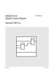
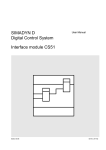
SIMADYN D
Digital Control System
User Manual
Subrack SRT
Edition 05.95
DK No. 213142
User Manual, Subrack SRT
Edition
1
Status
Subrack SRT
Copying of this document and giving it to others and the use or
communication of the contents thereof is forbidden without express
authority. Offenders are liable to the payment of damages. All rights
are reserved in the event of the grant of a patent or the registration of
a utility model or design.
We have checked the contents of this Manual to ensure that they
coincide with the described hardware and software. However,
deviations cannot be completely ruled-out, so we cannot guarantee
complete conformance. However, the information in this document is
regularly checked and the necessary corrections included in
subsequent editions. We are thankful for any recommendations or
suggestions.
05.95
Contents
Contents
Warning information................................ ................................ ................................ ...................... 1
1. Ordering information and supplementary components................................ ............................... 3
2. Function description................................ ................................ ................................ .................. 4
2.1. Overview ................................ ................................ ................................ ................... 4
2.2. Power supply and data transfer of the PC boards................................ ....................... 5
3. Mechanical design ................................ ................................ ................................ .................... 6
4. Power supply................................ ................................ ................................ ............................. 7
4.1. Front panel ................................ ................................ ................................ ................ 7
4.2. Line filter................................ ................................ ................................ .................... 7
4.3. Block diagram of the power supply voltages within the technology box ...................... 8
5. Installation guidelines................................ ................................ ................................ ................ 9
5.1. Installation information................................ ................................ ............................... 9
5.2. Noise immunity ................................ ................................ ................................ .......... 9
6. Technical data................................ ................................ ................................ ........................... 10
6.1. General data................................ ................................ ................................ .............. 10
7. STRUC mask in the master program................................ ................................ ......................... 11
8. Connector assignments................................ ................................ ................................ ............. 12
8.1. Parallel interface X2 to PT10 or CS51................................ ................................ ........ 12
9. Others................................ ................................ ................................ ................................ ....... 12
9.1. Attachments................................ ................................ ................................ ............... 12
9.2. Terminology/abbreviations................................ ................................ ......................... 12
10. ESD instructions................................ ................................ ................................ ...................... 13
Siemens AG Dk No. 213142
SIMADYN D Hardware User Manual
Edition 05.95
Warning information
Edition 05.95
Siemens AG Dk No. 213142
SIMADYN D Hardware User Manual
Warning information
NOTE!
The information in this Manual does not purport to cover all details or variations in equipment, nor to provide
for every possible contingency to be met in connection with installation, operation or maintenance.
Should further information be desired or should particular problems arise which are not covered sufficiently for
the purchaser’s purposes, please contact your local Siemens office.
Further, the contents of this Manual shall not become a part of or modify any prior or existing agreement,
committment or relationship. The sales contract contains the entire obligation of Siemens. The warranty
contained in the contract between the parties is the sole warranty of Siemens. Any statements contained
herein do not create new warranties nor modify the existing warranty.
Warning information
WARNING!
Electrical equipment has components which are at dangerous voltage levels.
If these instructions are not strictly adhered to, this can result in severe bodily
injury and material damage.
Only appropriately qualified personnel may work on this equipment or in its
vicinity.
This personnel must be completely knowledgeable about all the warnings and
service measures according to this User Manual.
The successful and safe operation of this equipment is dependent on proper
handling, installation, operation and maintenance.
Siemens AG Dk No. 213142
SIMADYN D Hardware User Manual
Edition 05.95
1
Warning information
Definitions
*
QUALIFIED PERSONNEL
*
DANGER
*
WARNING
*
CAUTION
*
NOTE
For the purpose of this User Manual and product labels, a „Qualified person“ is someone who is familiar with the
installation, mounting, start-up and operation of the equipment and the hazards involved. He or she must have
the following qualifications:
1. Trained and authorized to energize, de-energize, clear, ground and tag circuits and equipment in accordance
with established safety procedures.
2. Trained in the proper care and use of protective equipment in accordance with established safety
procedures.
3. Trained in rendering first aid.
For the purpose of this User Manual and product labels, „Danger“ indicates death, severe personal injury and/or
substantial property damage will result if proper precautions are not taken.
For the purpose of this User Manual and product labels, „Warning“ indicates death, severe personal injury or
property damage can result if proper precautions are not taken.
For the purpose of this User Manual and product labels, „Caution“ indicates that minor personal injury or
material damage can result if proper precautions are not taken.
For the purpose of this User Manual, „Note“ indicates information about the product or the respective part of the
User Manual which is essential to highlight.
CAUTION!
This board contains components which can be destroyed by electrostatic
discharge. Prior to touching any electronics board, your body must be electrically
discharged. This can be simply done by touching a conductive, grounded object
immediately beforehand (e.g. bare metal cabinet components, socket protective
conductor contact).
WARNING!
Hazardous voltages are present in this electrical equipment during operation.
Non-observance of the safety instructions can result in severe personal injury or
property damage.
It is especially important that the warning information in all of the relevant
Operating Instructions are strictly observed.
2
Edition 05.95
Siemens AG Dk No. 213142
SIMADYN D Hardware User Manual
Ordering information and supplementary components
1. Ordering information and supplementary components
Type:
Order No. (MLFB) Designation
Internal item No.
SRT:
6DD 1682-0CF0
Technology box SRT
465 682 9025.00
PT10:
SE58:
SC58:
SC60:
6DD 3440-0AB0
6DD 3460-0AB0
6DD 3461-0AB0
6DD 3461-0AE0
Processor board PT10
Terminal block for PT10
Shielded round cable, 40 core for PT10
Shielded round cable, 34 core for PT10
465 440 9001.00
465 460 9001.00
465 461 9001.00
465 461 9004.00
Package consisting of PT10, SE58, SC58,
SC60
465 440 9001.30
PT10P1: 6DD 3440-0AB3
MS47:
SE59:
6DD 3440-0AB2
6DD 3440-0AB1
Memory sub-module for PT10
Incremental encoder board for PT10
465 440 9001.20
456 440 9001.10
PP1I:
PP1X:
UP3:
6DD 1670-0AE0
6DD 1670-0AD0
6DD 3462-0AB0
Parallel programmer (desk-top unit)
Parallel programmer (integrated unit)
Programming adapter for MS47
465 670 9004.00
465 670 9005.00
465 462 9001.00
SW20:
6DD 3470-0AC0
465 470 9002.00
SW20:
SW20:
SW30:
6DD 3470-0AC2
6DD 3481-0BA0
6DD 3470-0AD0
SW30:
SW30:
6DD 3470-0AD2
6DD 3481-0CA0
Angular synchronism on the memory submodule MS47
"
on floppy disk
Description, angular synchronism
Axial winder on the memory sub-module
MS47
"
on floppy disk
Description, axial winder
CS51:
6DD 1660-0AH1
Interface board CS51
465 660 9007.10
Siemens AG Dk No. 213142
SIMADYN D Hardware User Manual
Edition 05.95
465 470 9002.20
465 481 9010.00
465 470 9003.00
465 470 9003.20
465 481 9020.00
3
Function description
2. Function description
2.1. Overview
The SRT technology box is used for mounting SIMADYN D PC boards PT10, CS51. It also
additionally includes the power supply for both PC boards.
SIMADYN D
SIEMENS
1L
2N
3
4 PE
X3
X1
X5
Caution!
115/230V
X4
S1
X5
OK
fault
X6
X7
Reset
+5V
0V
-15V
+15V
Only for test
X8
1 GND
2 +24V
X2
Output
X9
X6
CS
PT
Each board has its specific slot which is identified on the front panel. The technology box can be
operated with or without the CS51 communications board.
Various standard software packages are offered for the PT10 technology board. User-specific openand closed-loop control and arithmetic functions can be implemented using the STRUC configuring
language.
The technology box power supply requires a 230V AC 50-60 Hz supply which can be switched-over
for 115V AC 50-60 Hz supplies.
The PC boards and the power supply are designed for operation without fans.
4
Edition 05.95
Siemens AG Dk No. 213142
SIMADYN D Hardware User Manual
Function description
2.2. Power supply and data transfer of the PC boards
The PC boards are connected together and with the power supply through a 64-core ribbon cable
connector. Each board has an 8 cm long ribbon cable. The ribbon cable with the 64-pin plug
connector is inserted into the power supply, the CS51 ribbon cable connector, into the PT10. This
ribbon cable connector establishes the connection between the power supply of the boards and data
transfer between PT10 and CS51.
Data transfer between PT10 and TS51 is realized through a 16-bit databus. A dual port RAM, 2K*8 is
provided on the CS51 for this purpose.
Siemens AG Dk No. 213142
SIMADYN D Hardware User Manual
Edition 05.95
5
Mechanical design
3. Mechanical design
Inclined front panel of
the technology box
Guide rails
Mounting studs
Shield
PC board
Screw connection to
the front panel
To mount the PC boards in the technology box, the front panel with 4 screws is removed from the
technology box. The front panel can be removed from the technology box together with the power
supply. The upper left and lower right of the front panel can be used to withdraw it.
The boards are screwed to the studs provided. The studs are screwed to the front panel. The ribbon
cable connectors are inserted on the boards before they are inserted.
6
Edition 05.95
Siemens AG Dk No. 213142
SIMADYN D Hardware User Manual
Power supply
4. Power supply
4.1. Front panel
The power supply is part of the technology box. It is screwed to the subrack front panel. The boards
are also screwed to the front panel. The technology box is supplied with mounted power supply.
The technology box power supply is established through the 4-pole terminal X1. The supply voltage is
230V AC 50-60 Hz. The unit can be switched-over to 115 V AC, 50-60 Hz supplies using switch S1.
The factory setting is for 230V AC.
X1
X1
X1
X1
pin
pin
pin
pin
1
2
3
4
phase conductor L
neutral conductor N
not connected
protective conductor PE
The protective conductor must be connected to Pin 4. It is not sufficient to just connect a
protective conductor to the subrack.
A fuse should be provided with the following operating data.
In
In
=
=
0.5A max (for Vn =230V DC)
1.0A max (for Vn =115V DC)
The power supply switch-on and switch-off routine is activated when the supply voltage is connected.
This involves establishing the 5V, +15V, -15V, +24V output voltages, a POWER FAIL control line,
and a RESET control line.
The subrack is powered-up when the supply voltage is connected. All of the interface boards used
must be supplied with power 100 ms before the system boards in order to prevent faults when
powering-up. This condition is guaranteed by simultaneously switching-in the power supply voltage for
the subrack and the interface boards.
The power supply also provides a 24 V DC output at terminal X2. It is used to supply terminal X9 on
the CS51 interface board. The CS51 requires a 24 V power supply for electrical isolation via its
RS484 interface, which cannot be realized via the 64 core ribbon cable.
Further, there is a RESET button, which can be used to activate the power-up/power-down routine. It
is recessed, to prevent erroneous actuation. The output voltages are not shutdown or established
when the power-down/power-up routine is activated via the RESET button.
The 5V, +15V, -15V and ground, supplied from the power supply are available at 4 test points (2 mm
sockets), for test purposes. They are short-circuit protected using series resistors.
Both LEDs indicate fault-free operation (green LED) and faulted operation (red LED) of the power
supply.
4.2. Line filter
The power supply has a line filter, which limits the radio interference voltage according to VDE 0871
to limit value class A.
Siemens AG Dk No. 213142
SIMADYN D Hardware User Manual
Edition 05.95
7
Power supply
4.3. Block diagram of the power supply voltages within the technology box
PC board
Ground
Electrical isolation
Safety extra-low voltage
Circuit
Power supply
AC
8
Edition 05.95
Siemens AG Dk No. 213142
SIMADYN D Hardware User Manual
Installation guidelines
5. Installation guidelines
5.1. Installation information
The SRT SIMADYN D subrack is self-ventilated. In order to guarantee adequate ventilation, there
must be sufficient air circulation in the subrack and the cabinet for the discharged subrack air.
This means that the subrack may not be operated in an enclosed cabinet, and the subrack discharged
air may not be restricted by equipment or other components. The same is true for the subrack air
intake. It is not permissible to locate a filter in front of the cabinet air slots.
If the subrack is used in an enclosed cabinet, then the cabinet must be force-ventilated.
A minimum clearance of 60 mm must be maintained above and below the subrack when mounting
other equipment or components. When locating two subracks one above the other, this means that a
120 mm clearance must be maintained between the two subracks, whereby the upper subrack must
be separated from the lower subrack by an air deflection plate.
5.2. Noise immunity
All SIMADYN D housings must be connected to the cabinet ground through the shortest possible
cable - at least 6 mm2 cross-section.
Potential equalization via the „PE“power supply connection is not adequate.
Shielded cables should be connected with the shield to the grounding- or shield rails and routed to the
terminal module, shielded.
All of the cabinets, networked for SIMADYN D drives should be connected using a potential
equalization cable, at least 16 mm2 cross-section.
The front panel must be connected when operated with the technology box housing.
It is not permissible to use undamped contactors together with SIMADYN D in a cabinet.
If undamped contactors (i.e. no RC elements) are used in cabinets next to SIMADYN D, a panel must
be mounted between the cabinets.
The protective conductor is connected at the subrack and power supply.
Siemens AG Dk No. 213142
SIMADYN D Hardware User Manual
Edition 05.95
9
Technical data
6. Technical data
6.1. General data
INSULATION GROUP
A ACC. TO VDE 011 PARA. 13 GROUP 2 AT
24V DC, 15V, 5VDC
0 TO 55 DEGREES C WITH FORCED VENTILATION
-40 TO +70 DEGREES C.
F ACC. TO DIN 40050
S ACC. TO DIN 40040
MOUNTED IN STATIONARY EQUIPMENT WHICH IS NOT
NECESSARILY VIBRATION-FREE
ES 902 C
2.5 kg
AMBIENT TEMPERATURE
STORAGE TEMPERATURE
HUMIDITY RATING
ALTITUDE RATING
MECHANICAL STRESSING
PACKAGING SYSTEM
WEIGHT
Output voltage/current
Baseload, min.:
Va1: +5.1V ± 0.1V
Ia1: 0 to 3 A
(5% of Ia1)
Baseload, min.:
Va2: +15V ± 0.300V
Ia2: 0 to 0.6 A
(5% of Ia2)
Baseload, min.:
Va3: -15V ± 0.300V
Ia3: 0 to 0.6 A
(5% of Ia3)
Va4: +24V ± 2.0V
Ia3: 0 to 0.5 A
Residual ripple
(measurement bandwidth, 30 MHz)
(above 10% of the base load)< 50 mVpp Va1
(probe 1:1)
< 150 mVpp Va2,Ua3
Commutating spikes
(% of VaN)
± 5%
Current limiting
Ia1max = approx. 1.2 x Ia1
Ia2max = approx. 1.2 x Ia2
Ia3max = approx. 1.2 x Ia3
Shock/vibration stressing
Stationary application:
Transport:
acc. to SN29010
severity 12
severity 22
Degree of protection:
IP00
VDE 0110
Pollution level 2
VDE 0110
Air-creepage distances
Radio interference suppression VDE0871 limit value class "A"
10
Edition 05.95
Siemens AG Dk No. 213142
SIMADYN D Hardware User Manual
STRUC mask in the master program
1. Input voltages: at Ve = 230V
DC power supply acc. to SN 26555 Part 8, DIN IEC 38 Draft
Static upper limit
Static lower limit:
Frequency:
Ve * 1.1 (=253V)
Ve * 0.85 (=195.5V)
50/60 Hz ±2.5 Hz
Non-periodic overvoltages acc. to DIN VDE160, A5.3.1.1.2
V referred to the peak value: Ve * 1.3 (460V)
Duration:
0.3 ms
Recovery time, min.:
0.1 s
Events per hour:
10 max.
Brief voltage dips according to DIN VDE 0160, A5.3.1.1.3
V
0
Duration:
5 ms
Recovery time, min.:
0.1 s
Events per hour:
10 max.
Vcc: Va1 - voltage drop across the switching element
2 overvoltage protection for Va1
via suppressor diode
3 input voltage protection
fuse
4 safety regulations
(Standard, VDE 0160 December 1990; IEC)
5 rated insulation voltage:
3750 V AC
Test voltage:
Protective separation:
acc. to VDE 0160
Safety extra-low voltage according to VDE
0805 / EN 60950 with protective separation
7. STRUC mask in the master program
The technology box does not have its own STRUC mask. Any subrack can be configured in the
master program.
: SRT
"2-slot subrack, L bus"
L01 4S = '.
.
.
.
´"lettering"
L05 4S = '.
.
.- - - - - - SP - - - - ´"strip "
S01 8N = ?
"Slot 1: Subrack“
S02 8N = 0
S03 8N = 0
S04 8N = 0
S05 8N = 0
S06 8N = 0
++++++++++++++++++++++++++++++++++++++++++++++++++++++
Siemens AG Dk No. 213142
SIMADYN D Hardware User Manual
Edition 05.95
11
Connector assignments
8. Connector assignments
8.1. Parallel interface X2 to PT10 or CS51
X2 ( 64-core ribbon cable to PT10 or CS51)
Pin
Function
Pin
Function
1
3
5
7
9
11
13
15
17
19
21
23
25
27
29
31
33
35
37
39
41
43
45
47
49
51
53
55
57
59
61
63
AD0
AD1
AD2
AD3
AD4
AD5
AD6
AD7
AD8
AD9
AD10
AD11
AD12
AD13
AD14
AD15
ALE
L_WR
L_RESET
L_RD
L_READY
L_BHE
--SYNC
ME
PWR_FAIL
--ME
--P5
P5
P5
2
4
6
8
10
12
14
16
18
20
22
24
26
28
30
32
34
36
38
40
42
44
46
48
50
52
54
56
58
60
62
64
M
M
M
M
M
M
M
M
M
M
M
M
M
M
M
M
ME
ME
ME
ME
ME
ME
ME
ME
--L_CSPER1
L_INT
L_STAT1E
----P15
N15
9. Others
9.1. Attachments
Dimension drawing
3SE.465 682 9025.00 MB
9.2. Terminology/abbreviations
SV power supply
BGT subrack
12
Edition 05.95
Siemens AG Dk No. 213142
SIMADYN D Hardware User Manual
ESD instructions
10. ESD instructions
Components which can be destroyed by electrostatic discharge (ESD)
Generally, electronic boards should only be touched when absolutely necessary.
The human body must be electrically discharged before touching an electronics board. This can be
simply done by touching a conductive, grounded object directly beforehand (e.g. bare metal cubicle
components, socket outlet protective conductor contact).
Boards must not come into contact with highly-insulating materials - e.g. plastic foils, insulated
desktops, articles of clothing manufactured from man-made fibers.
Boards must only be placed on conductive surfaces.
When soldering, the soldering iron tip must be grounded.
Boards and components should only be stored and transported in conductive packaging (e.g.
metalized plastic boxes, metal containers).
If the packing material is not conductive, the boards must be wrapped with a conductive packing
material, e.g. conductive foam rubber or household aluminum foil.
The necessary ESD protective measures are clearly shown in the following diagram.
a = Conductive floor surface
b = ESD table
c = ESD shoes
Seated
Siemens AG Dk No. 213142
SIMADYN D Hardware User Manual
d = ESD overall
e = ESD chain
f = Cabinet ground connection
Standing
Edition 05.95
Standing / sitting
13
ESD instructions
14
Edition 05.95
Siemens AG Dk No. 213142
SIMADYN D Hardware User Manual
ESD instructions
Drives and Standard Products
Motors and Drive Systems Group
Postfach 3269, D-91050 Erlangen
Siemens AG Dk No. 213142
SIMADYN D Hardware User Manual
System-Based
Drive
Technology
Edition 05.95
15