1
User Manual V1.1
Page 3 of 19
Table index
Table 2-1 Simple 21E1-155M-SDH indicating lights .............................................................. 5
Table 2-2-1 EOW telephone interface.................................................................................... 8
Table 2-2-2 RS232 serial interface definition (RJ-45 end) ..................................................... 9
Table 4-2-1 Recommend measure instruments ................................................................... 17
Table 5-3-1 Technical indicators of STM-1 optical interface ................................................ 18
Table 5-3-2 E1 tributary interface......................................................................................... 18
Table 5-3-3 EOW interface .................................................................................................. 18
Table 5-3-4 Serial NMU ....................................................................................................... 19
Table 5-3-5 Ethernet NMU ................................................................................................... 19
Figure index
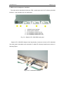
Fig. 2-1-1 The front panel....................................................................................................... 6
Fig. 2-1-2 The indicators of the front panel ............................................................................ 7
Fig. 2-1-3 The NE address switch .......................................................................................... 7
Fig. 2-2-1-1 EOW cable ......................................................................................................... 8
Fig. 2-2-1-2 EOW card ........................................................................................................... 8
Fig. 2-2-2 Serial interface structure ........................................................................................ 9
Fig. 2-3-1 Simple 21E1-155M-SDH back panel ................................................................... 10
Fig. 2-3-2 E1 tributaries interface ......................................................................................... 10
Fig. 2-3-3 the cable for 4xE1 ................................................................................................ 11
Fig. 2-3-4 E1 cable pin-out................................................................................................... 11
Fig. 3-1 Point to Point Network............................................................................................. 12
Fig. 3-2 Simple Chain Network............................................................................................. 12
Fig. 4-1-4-1 GND Jumpers ................................................................................................... 14
Fig. 4-1-4-2 System grounding............................................................................................. 14
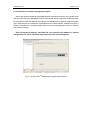
Fig. 4-1-5 Easy SDHTM Management system main interface ............................................... 15