Download 622X 622M cross-connected SDH Optical Transmission System

Transcript
622X
622M cross-connected SDH
Optical Transmission System
User’s Manual
V1.11
Jun.2008
RSM-622X User’s Manual V1.11
Page 2
Revision History
REVISION
DATE
DESCRIPTION
V1.00
2005-11-25
Creation of File
V1.01
2005-12-26
V1.10
2007-12-10
Modify the E1 cable order of serial
management and auxiliary user channel.
V1.11
2008-6-20
Modify the page description
Modification of Figure of Equipment Panel
Addition of Figures of Functional Blocks
Table of Contents
1. Introduction ............................................................................................................. 6
1.1 Overview.................................................................................................................. 6
1.2 Product Features ..................................................................................................... 6
1.3 Compliant Technical Specifications and Standards ................................................. 7
2. Front Panel ............................................................................................................. 7
2.1 Front Panel Introduction .......................................................................................... 7
2.2 Serial NM and User Channel(RS232) .............................................................. 9
2.3 Ethernet NM Interface ............................................................................................. 9
3. Rear Panel ............................................................................................................. 9
3.1 Rear Panel Introduction ........................................................................................... 9
3.2 Power Supply Interface ........................................................................................... 9
3.3 NE Address............................................................................................................ 10
3.4 STM-4 Optical Interface ......................................................................................... 10
4. Function Structure ................................................................................................ 10
4.1. STM-4/1 Optical Interface Unit ............................................................................. 11
4.2. DXC (Data Cross Connection) Unit ...................................................................... 11
4. 3.SOT (Segment Overhead Terminal) Segment Overhead Terminal Unit................ 11
4.4 SET (SDH Equipment Timing) Equipment Timing ............................................... 12
4.5. NMU (Network Management Unit) Network Management Unit .......................... 12
5. Networking Application ......................................................................................... 12
5.1 Direct Upgrade of Existing STM-1 Network to STM-4 Network ........................... 12
5.2 Realization of E1 Tributaries Access into STM-4 Loop .......................................... 13
6. Equipment Grounding........................................................................................... 13
7. Installation of NM System ..................................................................................... 14
8. MAC address ........................................................................................................ 14
9. Technical Parameters ........................................................................................... 15
10.
Physical Dimension and Environmental Requirements..................................... 15
Appendix
622X device fittings table ........................................................................ 16
RSM-622X User’s Manual V1.11
Page 3
Table Index
Table 2-1-1 Front panel ports and mask switch............................................................................................. 8
Table 2-1-2 Front Panel indicators.............................................................................................................. 8
Table 2-1-3
Urgent Alarm and delayed Alarm ............................................................................................. 8
Table 2-2-1 Cable order of Serial network management and user channel .................................................. 9
Table 9-3 Serial NM Interface (RS232) ....................................................................................................... 15
Table 9-4 Ethernet NM Interface (NMU) ...................................................................................................... 15
Table10-1 Physical Dimension .................................................................................................................... 15
Table10-2 Environmental Requirements ..................................................................................................... 15
Figure Index
Fig.2-1-1 Front panel of 622X ....................................................................................................................... 7
Fig 3-1-1
Rear Panel of 622X ..................................................................................................................... 9
Fig 3-3-1 Setting of NE Address ............................................................................................................... 10
Fig 4-1 RSM-622X Functional Block ........................................................................................................... 10
Figure 4-2 Default Configuration of Cross Connection................................................................................ 11
Figure 4-3 User Channel Forward Enabling Configuration ......................................................................... 12
Fig 5-1 Networking Application 1................................................................................................................. 13
Fig 5-2 Networking Application 2................................................................................................................. 13
Fig 6-1 Equipment External Grounding ....................................................................................................... 14
Fig 7-1 EasySDHTM NM System Main Interface ....................................................................................... 14
RSM-622X User’s Manual V1.11
Page 4
Abbreviations
ADM
Add-Drop Multiplexer
AIS
Alarm Indication Signal
ALS
Automatic Laser Shutdown
APS
Automatic Protection Switching
AU
Administrative Unit
AUG
Administrative Unit Group
BER
Bit Error Ratio
BLSR
Bidirectional Line Switched Ring
SES
Severely Error Seconds
DCC
Data Communications Channel
DEG
Degraded
DXC
Digital Cross Connect
ES
Error Second
ID
Identifier
LC
Link Connection
LOF
Loss Of Frame
LOM
Loss Of Multi-frame
LOP
Loss Of Pointer
LOS
Loss of Signal
LP
Lower order Path
LTI
Loss of all Incoming Timing references
MCF
Message Communications Function
MS
Multiplex Section
MSOH
Multiplex Section Overhead
NDF
New Data Flag
NE
Network Element
NNI
Network Node Interface
NU
National Use
OFS
Out-of-Frame Second
OOF
Out Of Frame
OW
Order Wire
PDH
Pre-synchronous Digital Hierarchy
PLM
Payload Mismatch
PPI
PDH Physical Interface
PJE
Pointer Justification Event
POH
Path Overhead
PTR
Pointer
RDI
Remote Defect Indication
RSM-622X User’s Manual V1.11
REI
Remote Error Indication
RS
Regenerator Section
RSOH
Regenerator Section Overhead
SD
Signal Degrade
SDH
Synchronous Digital Hierarchy
SEC
SDH Equipment Clock
SES
Severely Error Second
SETS
Synchronous Equipment Timing Source
SPI
SDH Physical Interface
SNC
SubNetwork Connection
SOH
Section Overhead
SSM
Synchronization Status Message
STM
Synchronous Transport Module
TIM
Trace Identifier Mismatch
TMN
Telecommunications Management Network
TS
Time Slot
TU
Tributary Unit
TUG
Tributary Unit Group
ULSR
Unidirectional Line Switched Ring
UNEQ
Unequipped
UNI
User Network Interface
USR
User channels
VC
Virtual Container
Page 5
RSM-622X User’s Manual V1.11
Page 6
1. Introduction
1.1 Overview
RSM-622X (STM-4) optical synchronous transmission system is one of the Raycom’s
important members of transmission equipment , which comply with the Synchronous Digital
Hierarchy (SDH) defined in ITU-T Recommendation G.707. It features high degree of
integration, exquisite conformation, flexible networking, strong network adaptability, and
other advantages. It is also comply with requirements of vibration, radiation, as well as
electromagnetic compatibility, and other multiple international specifications.
RSM-622X provides two 622.080Mb/s optical interfaces called E and F, and four
155.520155.520Mb/s optical interfaces of A, B, C, D. It also provides Network Elements (NE)
timing function of ITU-T G.813 standard, 14×14 VC4 fully cross connection and channel
protecting function with cross granularity as VC4, VC3 and VC12.
RSM-622X can either work together with RSM-155 series SDH equipments, as
Add-Drop Multiplexer (ADM) , as a Terminal Multiplexer (TM) or as a mini local
cross-connect for applications in linear links, rings, and meshed networks.
RSM-622X can also serve as Digital cross connecting equipment when working with
SDH device other manufacturers, and can achieve a smooth upgrade from STM-1 to STM-4,
while producing no impact on the existing NM system.
The NE management of RSM-622X system is based on a unified Network Management
System – EasySDH.
EasySDH is designed in accordance with ITU-T related
recommendations, to achieve management on network resources, equipment configuration,
alarm, performance, and security. It is also able to support the unified management of
subnetworks, with multiple optical paths which are not mutually connected, to support
remote network monitoring and control by Internet.
1.2 Product Features
◆ Single board, with 1U height
◆ Four STM-1 optical interfaces work independently or be set as 1+1 ring protection
◆ Two STM-4 optical interfaces work independently or be set as 1+1 optical ports
protection
◆ Standard SEC (SDH Element Clock) recommend by ITU-T G.813, synchronization
timing interface, SSM function and automatic switching of multiple timing reference
◆ Supports clock modes of tracing (locked), free run and holdover
◆ Non-blocked cross connection among six optical interfaces, the granularity of which are
VC4, VC3 and VC12
◆ Point-to-point, chain and ring topologies.
◆ Provides D1~D3 bytes of the ECC channel and TCP/IP as the network management
protocol
RSM-622X User’s Manual V1.11
Page 7
◆ Provides F (Ethernet) and f (RS232) NMS interface, network management platform
EasySDH. Realizes the resources, configuration, alarm, performance and security
functions proposed by ITU-T standards
◆ Embedded network management software supports remote upgrading
◆ Optional optical module of long/short distance and ALS/Non-ALS function
1.3 Compliant Technical Specifications and Standards
G.703
G.707
G. 781
G. 782
G. 783
G.784
G.803
G. 811
G. 813
G.823
G. 825
G. 826
G. 841
G. 957
G. 958
Physical/Electrical Properties of Digital Interfaces for Digital
Transmission Terminal Equipment
Network Node Interface of Synchronous Digital Hierarchy (SDH)
Composition of Related Recommendations for SDH Multiplexing
Equipment
Related Types and General Properties of SDH Multiplexing
Equipment
Function Block Properties of SDH Multiplexing Equipment
SDH Management
SDH’s Transmission Network Structure
Timing Requirements of Clock Output Terminal and Network Nodes
Applicable to international digital link PHD Operation
SDH Equipment Secondary Clock (SEC) Properties
Jitter and Drift Control in Digital Network Based on 2048Kb/s System
Jitter and Drift Control in Digital Network based on SDH
Bit Error Properties and Targets of Primary Group and above
International Fixed Rate Channels
Types and Properties for Protection of SDH Networks in Different
Structures
SDH-Related Optical Interfaces of Equipment and Systems
SDH Based Fiber Cable Digital Line Systems
The Ministry of Information Industry “Optical Synchronous Transmission Network
Technical System”
Governmental Standard “SDH Fiber Cable Line System Network Access
Requirements”
2. Front Panel
2.1 Front Panel Introduction
The front panel is arranged with STM-1 optical interface, equipment operating and alarming
LED, management interface and mask switch of alarm voice, etc.
A
OUT IN
B
OUT IN
C
OUT IN
D
OUT IN
RS232 NMU
RUN A B
5
6
7
C D E
8
Fig.2-1-1 Front panel of 622X
F XE1
ETH
ALAR M
MUTE
PHONE
RSM-622X User’s Manual V1.11
Page 8
Table 2-1-1 Front panel ports and mask switch
Name
Description
OUT
IN
Remark
STM-1 optical output
STM-1 optical input
Serial NM and user transparent
channel interface
RS232
NMU
Network management interface
RJ45 port, serial NM and user
transparent channel cable.
Note: the cable is not in the
packing list, it should be made by
customer
RJ45 port, use CAT-5 cross or
straight cable.
Note: the cable is not in the
packing list, it should be made by
customer.
ALARM(the button is up):Enable
the alarm voice
Mask switch
MUTE ( the button is push
down):mask the alarm voice
Table 2-1-2 Front Panel indicators
Name
Description
RUN
Run indicator, Green. Lighting means work well.
Optical Interface Status Indication. Off indicates that this optical interface
does not exist, green indicates normal operation, red means urgent
alarm, and yellow stands for delayed alarm.
Status Indication of extended service card. Not use temporarily.
A/B/C/D/E/F
XE1
Table 2-1-3
Urgent Alarm and delayed Alarm
Name
Description
Equipment Urgent
Alarm
The default urgent alarm including:
NOP (NO Power)
LOF (Loss of Frame)
MS_EXC ( Multiplex Section Excessive errors)
AU_LOP (Administrative Unit Loss of Pointer)
HP_PLM (Higher order Path Payload Mismatch)
HP_TIM (Higher order Path Trace Identifier Mismatch)
HP_EXC ( Higher order Path Excessive errors))
TU_LOP (Tributary Unit Loss of Pointer)
Equipment Delayed
Alarm
The default delayed alarm including:
MS_AIS (Multiplex Section Alarm Indication Signal)
MS_RDI (Multiplex Section Remote Defect Indication )
MS_DEG ( Multiplex Section Degraded)
HP_AIS (Higher order Path Alarm Indication Signal)
HP_RDI (Higher order Path Remote Defect Indication)
TU_AIS ( Tributary Unit Alarm Indication Signal)
LTI (Loss of all main Incoming Timing references)
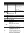
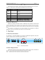
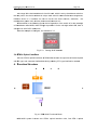
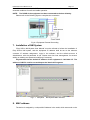
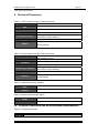
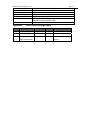
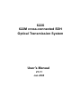
RSM-622X User’s Manual V1.11
2.2
Page 9
Serial NM and User Channel(RS232)
622X provide RJ-45 interface, used for serial network management and user channel.
Table 2-2-1 Cable order of Serial network management and user channel
Pin
PIN1
PIN2
PIN3
PIN4
PIN5
PIN6
PIN7
PIN8
Definitio
n
RSNM-OUT
Remark
Serial NM
Voltage)
Channel
output
(RS232
input
(RS232
RSNM-IN
Serial NM
Voltage)
GND
Data-IN
Data-OUT
Null
Null
Null
Signal GND
Serial data input(RS232 Voltage)
Serial data output(RS232 Voltage)
Channel
2.3 Ethernet NM Interface
Besides the RS232 Serial NM Interface,RSM-622X also provides an Ethernet NM
interface called NMU, Either standard cross network cable or through one can be used in
the connection between the interface and the NMS The cable order will not be described
here
The customer can change the mac and ip address of the equipment to fulfill the
application, refer to the “EasySDH user manual” for more information.
3. Rear Panel
3.1 Rear Panel Introduction
The following is a schematic diagram for rear panel of RSM-622X equipment, with power
interface, address switch, and STM-4 optical interface, etc.
~220V
PGND GND -48V
ADDRSS
MSB
LSB
POWER
E
OUT IN
F
OUT IN
1
0 1 2 3 4 5 6 7 8
×10
Fig 3-1-1
×1
Rear Panel of 622X
3.2 Power Supply Interface
The device provide two power supply interface, AC220V and DC-48V, the default is
DC-48V. The AC 220V power interface should be declare in the order.
Note: AC220V and DC-48V cannot be used at the same time!
RSM--622X User’s Manual
M
V1.11
Page 10
0
3.3 NE
N Addres
ss
The range of
T
o the device
e address is from 00 to 98,
9 which is set by the a
address swittch on
the re
ear panel. The
T device address
a
is unique mark used for ne
etwork eleme
ent management,
Differrent device in a netw
work can no
ot be set to
t the same address, otherwise, the
mana
agement sysstem can’t achieve
a
the successful
s
access
a
to it.
A described in the follo
As
owing figure
e, the left 4-p
position of the switch iss for the tens
s digit
of the
e address called MSB, while the rig
ght 4-positio
on is for the unit digit ca
alled LSB, both of
which
h are in 8421 BCD code
e mode.
T
Take
the exa
ample of the
e figure, the address is “11”
“
Fig 3-3-1
Setting off NE Addresss
3.4 STM-4
S
Optical Interfface
The two STM-4 optical interfaces of
T
o RSM-622X
X locates on
n right side o
of the back panel
with SC
S type, and customer shall declarre during ord
dering if FC type interfacce is needed
d.
4. Function
F
n Structu
ure
A
ST
TM-1
B
STM
M-1
STM
M-4
C
D
STM-1
1
STM-1
ST
TM-4
DXC
E
SETS
S
NMU
F
SOT
Fig 4-1 RSM
M-622X Functional Block
system inccludes two STM-4 optical interface units, fou
R
RSM-622X
ur STM-1 optical
o
RSM-622X User’s Manual V1.11
Page 11
interface units, functional modules of data cross connection(DXC), overhead transaction
(SOT), equipment timing source(SETS), management unit(NMU) and etc.
4.1. STM-4/1 Optical Interface Unit
It fulfills process of STM-1/STM-4 optical signal in SDH system, including the section
overhead (SOH) and high-order channel overhead process, pointer process, TU pointer
alignment (TUPP) and so on.
It can achieve automatic laser shutdown (ALS) function or super-long distance
transmission by changing particular optical module, which physical interface can be FC
or SC.
4.2. DXC (Data Cross Connection) Unit
It is able to achieve cross-through, broadcast, add/drop and loop cross connection.
Any cross connection mode can be achieved for service entering into the lines and the
tributaries inside the equipment.
For the convenience of application, the four VC4s of the E optical interfaces
(STM-4) are defined as E_1, E_2, E_3, and E_4 in turn, and the four VC4s of F optical
interface (STM-4) as F_1, F_2, F_3, and F_4, respectively.
The equipment default configuration is ,E and F optical interfaces are in mutual
protection,all service channels are TU-12, four STM-1 optical interfaces of A to D are
independent for adding and dropping service, respectively cross connect with E_1
(F_1), E_2 (F_2), E_3 (F_3), and E_4 (F_4), as indicated in the following figure.
Figure 4-2 Default Configuration of Cross Connection
4. 3.SOT (Segment Overhead Terminal) Segment Overhead Terminal Unit
It is to achieve termination and insertion for the part of segment overhead. One RS-232
bus channel is provided, using F1 of overhead for transmission. The option for service
initiating site “F1 Transmission Enable” must be set as Disable in application, and that
for other sites are to be set as Enable. And ensure that there is only one site which send
data to the bus at any moment.
RSM--622X User’s Manual
M
V1.11
Page 12
2
Figure
e 4-3 User Channel
C
Forw
ward Enablin
ng Configura
ation
DCC channel
c
, which
w
occu
upy D1~D3,, used for communica
ation of ne
etwork
e
elements.
EOW in
nterface is not
n provided
d by the equ
uipment; how
wever, when
n connecting
g with
o
other
SDH equipment of our com
mpany, E1 overhead byte
b
used ffor EOW ca
an be
automaticallly, to ensu
c
configured
ure that orriginal telep
phone syste
em can op
perate
n
normally.
nally, to havve no impact on the NM
N system of
o other ma
anufacture whose
w
Addition
e
equipment
c
connected
w RSM-62
with
22X, standb
by overhead of E1’/F1’/D1’~D3’ use
ed for
N are provvided .The “route
NM
“
way settings”
s
is set to be “n
non standard
d” through NM
N to
r
realize
the usage
u
of stan
ndby overhe
ead.
4.4
SET (SDH Equipm
ment Timin
ng) Equipm
ment Timin
ng
It is to provide interface for external tim
ming signalss and the timing sourrce of
equipment, to
e
t give a tim
ming referencce to differen
nt functional modules off SDH equipment.
It provid
des a selecttive clock fu
unction of diffferent priority, using S1
1 byte, as well
w as
c
complete
fu
unction for synchronous
s
s status me
essages (SSM), to ensure the re
eliable
o
operation
off clock. It can
n track A, B, C, D, E, an
nd F six line
e timing sourrces (LTS), and
a is
a
able
to achie
eve automattic switch ba
ased on qua
ality levels off timing sourrce.
4.5.
NMU (Ne
etwork Ma
anagemen
nt Unit) Ne
etwork Ma
anagementt Unit
It fulfill the manage
ement of the
e equipmentt and comm
munications b
between ne
etwork
e
elements,
an
nd provide an
a Ethernet interface an
nd an RS-23
32 interface ffor access.
5. Network
N
king Appllication
5.1
Direct Up
pgrade of Existing STM-1
S
Network to STM-4
S
Nettwork
Establishing
E
g on the exisstent STM-1 equipment by STM-1 optical
o
interfface, RSM-6
622 X
is ab
ble to upgrade the orriginal STM--1 network to STM-4 network, sso as to en
nlarge
transsmission cap
pacity.
I the origina
If
al STM-1 is an equipme
ent of anothe
er manufactturer, overhe
ead mode can be
set th
hrough NM software,
s
to retain the NM
N system of
o the origina
al equipmen
nt.
RSM-622X User’s Manual V1.11
Page 13
STM-1 NE2
622X
622X
STM-1 NE3
STM-4 Ring
STM-1 NE1
622X
STM-1 NE2
STM-1 NE3
STM-1 Ring
STM-1 NE1
Fig 5-1 Networking Application 1
5.2 Realization of E1 Tributaries Access into STM-4 Loop
The four STM-1 optical interfaces provided by RSM-622X, can serve as up and down
optical tributary services, in cooperation with RSM-155C/CP, and can provide up to 252 E1.
622X
STM-4 Ring
622X
622X
4×STM-1
STM-1 NE1
252×E1
Fig 5-2 Networking Application 2
6. Equipment Grounding
As a small-sized equipment, RSM 622X ground is divided into two types-working
ground and protection ground. When equipment runs normally, it is necessary for GND and
PGND to be connected with the earth. The PGND resistance shall be not more than 4Ω and
RSM-622X User’s Manual V1.11
Page 14
2
the minimum cross section of GND wire should not be less than 6mm , so as to provide
essential conditions for safe and stable operation.
NOTE: The PGND of the equipment has been connected to the box defaultly.
Please refer to the following figure to complete the connection
Fig 6-1 Equipment External Grounding
7. Installation of NM System
“Easy SDHTM NM System User Manual” must be referred to before the installation of
Easy SDHTM NM system, and the equipment IP address shall be set as the advance
customer IP address assignment. Login in the software, and the default account is
Administrator, with the password is null. Please enter into user management for account
adding or deleting and password modifying if necessary.
Pay attention that the default IP address of the equipment is 192.168.0.157. The
address of NM PC shall be set and kept at the identical IP segment.
Fig 7-1
EasySDHTM NM System Main Interface
8. MAC address
The device is assigned by a unique MAC Address in the world, which was stunk on the
RSM-622X User’s Manual V1.11
Page 15
side face of the device.
9. Technical Parameters
Table 9-1 STM-1 Optical Interface Technical Indices
1310nm
Working Wavelength
Rate
Standard
Type of Medium
Transmission Distance
Receiving Sensitivity
155.520Mb/s± 4.6ppm
ITU-T G.957/G.958
ITU-T G.652/G.653, Single-mode
40Km (Optional for long-distance transmission, and user
must specify during ordering.)
prior to –36dB
FC (optional for SC interface ,and user must specify
Adapter
during ordering)
Table 9-2 STM-4 Optical Interface Technical Indices
1310nm
Wavelength
Rate
Standard
Type of Medium
Transmission Distance
Receiving Sensitivity
622.080Mb/s±4.6ppm.
ITU-T G.957/G.958.
ITU-T G.652/G.653, Single-mode
40Km (optional for long-distance transmission, and user
must specify during ordering)
prior to –28dB
SC, optional for FC interface, and user must specify
Interface
during ordering.
Table 9-3 Serial NM Interface (RS232)
Rate
Interface
19200b/s
RJ45
Table 9-4 Ethernet NM Interface (NMU)
Mode
Interface
10/100Mb/s, Half/Full duplex autonegotiation
RJ45
10. Physical Dimension and Environmental Requirements
Table10-1 Physical Dimension
Size
483mm (L) x 290mm (W) x 44mm (H)
Weight
4.0kg
Table10-2 Environmental Requirements
Project
parameters
RSM-622X User’s Manual V1.11
Page 16
Power Supply
Power consumption
Operating temperature
Relative Humidity
Air Pressure
Environmental Air
DC:-36V~-72V;AC:176V~275V
35W±10%
0~45°C
≤90%(Non-condensing)
70~106Kpa
be away from corrosive, solvent gases, dust, and not
adjacent to strong magnetic field.
Grounding requirement
Resistance : ≤4Ω
Appendix
622X device fittings table
No
Name
Specification
quantity
1
Fuse
3A
1
RJ-45
3
2
Modular plug
Remarks
Used in Double power
3
200V power cable
1
supply