1
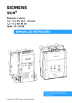
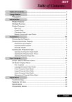
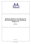
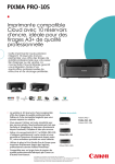
ISA-GPIB-PC2A
User’s Manual
Revision 5
November, 2000
MEGA-FIFO, the CIO prefix to data acquisition board model numbers, the PCM prefix to data
acquisition board model numbers, PCM-DAS08, PCM-D24C3, PCM-DAC02, PCM-COM422,
PCM-COM485, PCM-DMM, PCM-DAS16D/12, PCM-DAS16S/12, PCM-DAS16D/16,
PCM-DAS16S/16, PCI-DAS6402/16, Universal Library, InstaCal, Harsh Environment
Warranty and Measurement Computing Corporation are registered trademarks of Measurement
Computing Corporation.
IBM, PC, and PC/AT are trademarks of International Business Machines Corp. Windows is a
trademark of Microsoft Corp. All other trademarks are the property of their respective owners.
Information furnished by Measurement Computing Corp. is believed to be accurate and
reliable. However, no responsibility is assumed by Measurement Computing Corporation
neither for its use; nor for any infringements of patents or other rights of third parties, which
may result from its use. No license is granted by implication or otherwise under any patent or
copyrights of Measurement Computing Corporation.
All rights reserved. No part of this publication may be reproduced, stored in a retrieval system,
or transmitted, in any form by any means, electronic, mechanical, by photocopying, recording
or otherwise without the prior written permission of Measurement Computing Corporation.
Notice
Measurement Computing Corporation does not authorize any
Measurement Computing Corporation product for use in life support
systems and/or devices without the written approval of the President of
Measurement Computing Corporation Life support devices/systems are
devices or systems which, a) are intended for surgical implantation into
the body, or b) support or sustain life and whose failure to perform can
be reasonably expected to result in injury. Measurement Computing
Corp. products are not designed with the components required, and are
not subject to the testing required to ensure a level of reliability suitable
for the treatment and diagnosis of people.
(C) Copyright 2000, Measurement Computing Corporation.
HM ISA-GPIB-PC2A.lwp
TABLE OF CONTENTS
1 INTRODUCTION . . . . . . . . . . . . . . . . . . . . . . . . . . . . . . . . . . . . . . . . . . . . . . . . . . 1
1.1 NATIONAL INSTRUMENTS PCII & PCIIA OWNERS . . . . . . . . . . . . . . . 1
1.2 GPIB HISTORY . . . . . . . . . . . . . . . . . . . . . . . . . . . . . . . . . . . . . . . . . . . . . . . . 1
1.3 GPIB SYSTEM DESCRIPTION . . . . . . . . . . . . . . . . . . . . . . . . . . . . . . . . . . . 2
1.3.1 Talkers, Listeners, and Controllers . . . . . . . . . . . . . . . . . . . . . . . . . . . . . . 2
1.3.2 GPIB Electrical Signal Configuration . . . . . . . . . . . . . . . . . . . . . . . . . . . 2
1.3.3 Data Lines . . . . . . . . . . . . . . . . . . . . . . . . . . . . . . . . . . . . . . . . . . . . . . . . . 3
1.3.4 Handshaking Lines . . . . . . . . . . . . . . . . . . . . . . . . . . . . . . . . . . . . . . . . . . 3
1.3.5 System Management Lines . . . . . . . . . . . . . . . . . . . . . . . . . . . . . . . . . . . . 3
1.4 CONNECTION CONFIGURATIONS . . . . . . . . . . . . . . . . . . . . . . . . . . . . . . 3
2 INSTALLATION . . . . . . . . . . . . . . . . . . . . . . . . . . . . . . . . . . . . . . . . . . . . . . . . . . 5
2.1 BOARD LAYOUT . . . . . . . . . . . . . . . . . . . . . . . . . . . . . . . . . . . . . . . . . . . . . 5
2.2 BASE ADDRESS . . . . . . . . . . . . . . . . . . . . . . . . . . . . . . . . . . . . . . . . . . . . . . . 5
2.3 INTERRUPT LEVEL SELECT . . . . . . . . . . . . . . . . . . . . . . . . . . . . . . . . . . . 6
2.4 WAIT STATE JUMPER & DMA JUMPERS . . . . . . . . . . . . . . . . . . . . . . . . 8
3 REGISTER MAPS . . . . . . . . . . . . . . . . . . . . . . . . . . . . . . . . . . . . . . . . . . . . . . . . . 9
3.1 ADDRESS DECODING . . . . . . . . . . . . . . . . . . . . . . . . . . . . . . . . . . . . . . . . . 9
3.2 NI PCII REGISTERS (NOT ISA-GPIB-PC2A) . . . . . . . . . . . . . . . . . . . . . . 9
3.3 ISA-GPIB-PC2A (NI PCIIA) REGISTERS . . . . . . . . . . . . . . . . . . . . . . . . . 10
3.4 ISA-GPIB-PC2A (NI PCIIA) REGISTERS . . . . . . . . . . . . . . . . . . . . . . . . . 10
3.5 CONVERTING PCII DRIVERS FOR THE ISA-GPIB-PC2A . . . . . . . . . . 11
This is a blank page.
1 INTRODUCTION
The ISA-GPIB-PC2A is a 100% compatible replacement for the National Instruments
PCII, PCIIA and all other GPIB interfaces which are register and functionally
compatible with them. To set up the ISA-GPIB-PC2A , set the switches and jumpers
on the board to match the configuration of the GPIB interface board and software you
currently use.
1.1 NATIONAL INSTRUMENTS PCII & PCIIA OWNERS
The ISA-GPIB-PC2A is easy to use if you are familiar with the National Instruments,
Inc. PCIIA GPIB interface board. All of the ISA-GPIB-PC2A switches and jumpers
are in the same location and have the same function as the PCIIA.
If you are using the National Instruments PCII board, you will find that the switches
and jumpers are in a different location although the functions of the switches and
jumpers on the NI PCII and PCIIA are nearly identical.
Because the ISA-GPIB-PC2A is designed to be 100% compatible with the NI PCIIA
from the connector to the registers, and to look similar as well, references to the NI
PCIIA board in this manual apply to the ISA-GPIB-PC2A also.
This manual supplies information on switch settings and jumper position for base
address, DMA channel, interrupt level and wait state. Information on programming is
found in the manual for the software package you intend to use with the
ISA-GPIB-PC2A.
1.2 GPIB HISTORY
The GPIB (General Purpose Interface Bus) has become the worldwide standard for
connecting instruments to computers. Invented in the 1960s by Hewlett Packard and
originally designated as HPIB, the bus specification was eventually adopted by a wide
variety of both instrument and computer manufacturers. The original specification was
documented and sanctioned by the IEEE as IEEE-488.
The advent of the inexpensive and powerful personal computer has driven the GPIB
market through explosive growth. As GPIB bus usage expanded, there arose the need
for some additional capability and standardization, so in 1987, IEEE-488.2 was
adopted. IEEE-488.2 was revised/ammended in 1992 and represents the current GPIB
specification. The new specification provides some standardization among compliant
instruments. This standardization greatly simplifies the job of the GPIB system
designer since 488.2 compliant instruments share common programming conventions.
1
1.3 GPIB SYSTEM DESCRIPTION
1.3.1 Talkers, Listeners, and Controllers
A GPIB device can be a Talker, Listener, and/or Controller. As the name implies, a
Talker sends data to one or more Listeners, A Listener accepts data from a Talker and
a Controller manages the flow of information over the bus. A GPIB Digital Voltmeter
is acting as a Listener as its input configurations and ranges are set, and then as a
Talker when it actually sends its readings to the computer.
The Controller is in charge of all communications over the bus. The Controller’s job
is to make sure only one device tries to talk at a time, and make sure the correct
Listeners are paying attention when the Talker talks. Each GPIB system has a single
system controller. The system controller is ultimately in charge of the bus, and is in
control as the bus is powered up. There can be more than one Controller on the bus
and the System Controller can pass active control to another controller capable device,
though only one can be Controller In Charge at a given time. The GPIB board is
usually designated as the System Controller.
1.3.2 GPIB Electrical Signal Configuration
The GPIB is an 8-bit parallel data transfer bus. In addition to the eight data bits, the
bus carries three handshaking lines and five GPIB specific management and control
lines. The remainder of the standard 24-pin GPIB cable is used for the cable shield,
signal grounds and returns. The GPIB connector pin-out is shown in Figure 1-1
below:
13
14
15
16
17
18
19
20
21
22
23
24
D IO 1 1
D IO 2 2
D IO 3 3
D IO 4 4
EO I 5
DA/ 6
NRFD 7
NDAC 8
IFC 9
SRQ 10
AT N 11
S H IE L D 12
D IO 5
D IO 6
D IO 7
D IO 8
R EN
G N D (Tw is te d P a ir w ith
G N D (Tw iste d P a ir w ith
G N D (Tw iste d P a ir w ith
G N D (Tw iste d P a ir w ith
G N D (Tw iste d P a ir w ith
G N D (Tw iste d P a ir w ith
S IG N A L G R O U N D
G PIB Pinout as view ed looking
into connector on ISA-G PIB-PC2A
Figure 1-1 ISA-GPIB-PC2A Connector Pin-Out
2
D AV )
N R FD )
NDAC)
IF C )
SRQ)
AT N )
1.3.3 Data Lines
DIO1 through DIO8 are the data transfer bits. Most GPIB systems send 7-bit data
and use the eight bit as a parity or disregard it entirely
1.3.4 Handshaking Lines
There are three handshaking lines that control the data transfer between devices.
y
NRFD (Not Ready For Data): this bit is used to indicate the readiness (or lack
thereof) of a device to accept data
y
DAV (Data Valid): bit is used to indicate to receiving devices that data has been
placed on the bus and is available to read.
y
NDAC (Not Data Accepted): is asserted by the receiving device to indicate that
data has been read and may now be removed from the bus.
1.3.5 System Management Lines
y
ATN (Attention): is used by the controller to specify how data on the DIO lines
is interpreted and which devices must respond to the data
y
IFC (Interface Clear): is used by the system controller to place the entire system
in a known quiescent (Cleared) state and to assert itself as Controller In Charge
(CIC).
y
SRQ (Service Request): is used by a device on the bus to indicate the need for
attention and requests an interrupt of the current event sequence.
y
REN (Remote Enable): is used by the controller in conjunction with other
messages to place a device on the bus into either remote or local mode
y
EOI (End or Identify): Is used by Talkers to indicate the end of a message
string, or is used by the Controller to command a polling sequence.
1.4 CONNECTION CONFIGURATIONS
The GPIB specification is quite definitive regarding the number of devices and cable
lengths allowed in a GPIB system. There can be no more than 15 devices on a single
contiguous GPIB bus. Larger systems are possible by installing additional GPIB
interface boards in your computer
The maximum, total length of all cables on a single GPIB system is 20 meters. In
addition, cable length between consecutive devices must be no greater than four
meters, and average cable length must be two meters or less. Stated another way, the
total cable length (in meters) in the system cannot be longer than two times the
number of devices (up to 20 meters). Longer length systems are possible, but only
3
with the use of a GPIB extender card. In addition to the above rules, at least two-thirds
of all devices on the bus should be powered on for proper operation.
Keeping the above constraints in mind, there is no limitation on the actual connection
scheme used to connect the GPIB devices together. Star, Linear or any combination of
both may be used. These are shown in Figures 1-2 and 1-3 below.
,QVWUXPHQW $
L in ea r C o n ne ctio n
C o n fig u ra tio n
,QVWUXPHQW %
,QVWUXPHQW '
,QVWUXPHQW &
Figure 1-2. GPIB Linear Connection Configuration
S tar C on ne ctio n
C o nfiguration
,QVWUXPHQW $
,QVWUXPHQW %
,QVWUXPHQW '
,QVWUXPHQW &
,QVWUXPHQW (
Figure 1-3. GPIB Star Connection Configuration
4
2 INSTALLATION
2.1 BOARD LAYOUT
The ISA-GPIB-PC2A has one bank of switches and three jumper blocks which must
be set before installing the board in your computer.
COMPUTERBOARDS, INC.
Wait State
Generator
Selection
Base Address
Selection
Interrupt
Selection
0
1
2
14
13
2 3 4 5 6 7
1 1 2 2 3 3
A31
A1
DMA Channel Selection
ISA-GPIB-PC2A - Switch positions and functions are identical to those
on the NI PCIIA.
Figure 2-1. Board Switch and Jumper Locations
2.2 BASE ADDRESS
The base address of the ISA-GPIB-PC2A is set with the two switches labeled 14 and
13. Only four possible base addresses are available. In addition, there is considerable
'rollover', or addresses which are not deselected by the address enable circuitry of the
ISA-GPIB-PC2A.
The default address chosen by National Instruments for the PCIIA was 02E1h, so that
is the default setting for the ISA-GPIB-PC2A.
Unlike most other I/O boards, the National Instrument PCIIA uses nonconsecutive I/O
addresses and the ISA-GPIB-PC2A does the same to maintain compatibility.
5
The ISA-GPIB-PC2A I/O address is selected using
only the two lowest switches on the 5 position DIP
switch.
0
1
2
14
The upper three switches are interrupt select switched.
13
BASE ADDRESS = 02EI Both switches to the right.
Base Address = 02E1
Base Address = 22E1
Base Address = 42E1
Base Address = 62E1
ISA-GPIB-PC2A BASE ADDRESS SWITCH
Figure 2-2. Base Address Switches
Following are the tables of addresses also used for a given setting. Be sure that any
other I/O boards installed in your computer do not use one of these addresses.
02E1 06E1
12E1 16E1
0AE1
1AE1
0EE1
1EE1
22E1
32E1
26E1
36E1
2AE1
3AE1
2EE1
3EE1
42E1 46E1
52E1 56E1
4AE1
5AE1
4EE1
5EE1
62E1
72E1
66E1
76E1
6AE1
7AE1
6EE1
7EE1
The ISA-GPIB-PC2A uses eight I/O Addresses.
2.3 INTERRUPT LEVEL SELECT
The interrupt used by the ISA-GPIB-PC2A is set with three switches, a jumper, and
your software. All three must match or interrupts will not function properly.
6
The following table shows switch settings and jumper locations for each of the six
possible interrupts, 2 to 7.
0
ISA-GPIB-PC2A Interrupt logic is controlled by a combination of
switched 0, 1 & 2 and the interrupt jumper.
1
2
14
13
0
Switches 13 and 14, the lower two, select the base address.
2
3
4
5
6
7
0
1
1
2
2
2
3
4
5
6
3
4
5
6
7
0
2
3
4
5 6 7
1
1
2
2
Interrupt 4 Selected
Interrupt 5 Selected
Best for PC/AT
0
2
3
4
5
6
7
Interrupt 3 Selected
Interrupt 2 Selected
0
2
7
0
1
1
2
2
2
3 4 5 6 7
Interrupt 7 Selected
Factory Default for PC/AT
Interrupt 6 Selected
The six possible switch settings and jumper locations for each of
the interrupts, 2 to 7.
Figure 2-3. Interrupt Switch and Jumper Settings
National Instruments chose interrupt level 7 (IRQ7) as the default for the PCIIA.
Your ISA-GPIB-PC2A is configured at the factory for IRQ7.
Although IRQ7 is acceptable, that interrupt is reserved for the LPT1: printer device.
A better choice is IRQ5 on most machines.
7
2.4 WAIT STATE JUMPER & DMA JUMPERS
The ISA-GPIB-PC2A boards have a wait state jumper which enables an onboard wait
state generator. A wait state is an extra delay injected into the processor's clock via
the bus. This delay slows down the processor so that signals from slow devices
(chips) will be valid. You will probably not need a wait state since the I/O bus is
slowed down on even the fastest PCs. The default is no wait state selected.
The ISA-GPIB-PC2A can use DMA levels 1, 2, 3 or none. The factory default is
level 1.
Wait State Enabled
Wait State Disabled
1
1
2
2
3
3
1
DMA Channel 1
1
1
2
2
3
1
2
2
3
3
DMA Channel 3
3
1
1
2
2
3
3
No DMA Channel Selected
DMA Channel 2
ISA-GPIB-PC2A WAIT STATE & DMA SELECT
Figure 2-4. Wait State and DMA Select Jumpers
On PC/XT class machines, the hard disk controller usually occupies DMA level 3 and
the floppy disk controller usually occupies level 2. Neither level 2 nor 3 are a good
choice of DMA level on a PC/XT equipped with a floppy and hard disk.
On PC/AT/386 class computers, both DMA channels 1 and 3 are available.
8
3 REGISTER MAPS
3.1 ADDRESS DECODING
There are only four possible base addresses which can be selected using the switches
on the ISA-GPIB-PC2A. Those four base addresses are shown below in bold type.
For a given base address, the ISA-GPIB-PC2A registers appear at eight additional
addresses within the personal computer's I/O address space.
02E1 06E1
12E1 16E1
0AE1
1AE1
42E1 46E1
52E1 56E1
4AE1
5AE1
Table 3-1. Board Base Addressing
0EE1
22E1 26E1
1EE1
32E1 36E1
4EE1
5EE1
62E1
72E1
66E1
76E1
2AE1
3AE1
2EE1
3EE1
6AE1
7AE1
6EE1
7EE1
If the addressing scheme in the table above appears confusing and unconventional, we
agree, it is.
The addressing of the ISA-GPIB-PC2A is easiest to understand in relation to
National's PCII board (NI PCIIA). Here are the addresses of the PCII board.
3.2 NI PCII REGISTERS (NOT ISA-GPIB-PC2A)
ADDRESS
Base + 0
Base + 1
Base + 2
Base + 3
Base + 4
Base + 5
Base + 6
Base + 7
Table 3-2. NI PCII Registers
WRITE
READ
Byte out register
Byte In register
Interrupt Mask 1 register Interrupt Status 1 register
Interrupt Mask 2 register Interrupt Status 2 register
Serial Poll Mode register Serial Poll Status register
Address Mode register
Address Status register
Auxiliary Mode register
Command Pass-through register
Address Register 0/1
Address 0 register
End-Of-String register
Address 1 register
The addressing of the PCII is easy to understand. A Base-Address-Switch selects the
boards Base Address and the register functions on the board occupy consecutive I/O
addresses. Eight of them in total.
Complete descriptions of each register and it's functions follow in a later section.
9
Back to the ISA-GPIB-PC2A (NI PCIIA). The registers on the ISA-GPIB-PC2A are
the same as those of the NI PCIIA shown below. The logic of the address decoding is
very different. The eight registers are not consecutive. The registers are offset by
400h between each register.
3.3 ISA-GPIB-PC2A (NI PCIIA) REGISTERS
ADDRESS
Base +0
Base +400
Base +800
Base +C00
Base +1000
Base +1400
Base +1800
Base +1C00
2F0 + IR
Table 3-3 ISA-GPIB-PC2A (NI PCIIA Registers
WRITE
READ
Byte out register
Byte In register
Interrupt Mask 1 register Interrupt Status 1 register
Interrupt Mask 2 register Interrupt Status 2 register
Serial Poll Mode register Serial Poll Status register
Address Mode register
Address Status register
Auxiliary Mode register
Command Pass-through register
Address Register 0/1
Address 0 register
End-Of-String register
Address 1 register
Interrupt clear bit
Table 3-4 below is an example of the actual physical register addresses for a
ISA-GPIB-PC2A board Base Address of 02E1.
3.4 ISA-GPIB-PC2A (NI PCIIA) REGISTERS
Table 3-4. Physical Register Addresses for Board Base Address 02E1
ADDRESS
WRITE
READ
02E1
Byte out register
Byte In register
06EI
Interrupt Mask 1 register Interrupt Status 1 register
0AEI
Interrupt Mask 2 register Interrupt Status 2 register
0EE1
Serial Poll Mode register Serial Poll Status register
12E1
Address Mode register
Address Status register
16E1
Auxiliary Mode register
Command Pass-through register
1AE1
Address Register 0/1
Address 0 register
1EE1
End-Of-String register
Address 1 register
10
3.5 CONVERTING PCII DRIVERS FOR THE ISA-GPIB-PC2A
If you are working with your own PCII driver, converting it for the ISA-GPIB-PC2A,
is an easy task. The register functions of the PCII and ISA-GPIB-PC2A (NI PCIIA)
are identical, the addressing is very different. Refer to the prior descriptions to learn
how different.
If you have hard-coded all the addresses into your driver, converting your driver to
work with both the PCII and ISA-GPIB-PC2A will require that you replace all the
hard-coded addresses with variables.
If you have referenced all other addresses as an offset from the base address, such as
IN Base+4 or OUT Base+7, you will have to replace each such reference with
variable names. Table 3-5 is a list of proposed variable names.
Table 3-5. Proposed ISA-GPIB-PC2A Registers Mnemonics
ADDRESS
WRITE
READ
Base + 0
BOR
Byte Out
BIR
Byte In
Base + 400
IRM1 Interrupt Mask 1 IRS1 Interrupt Status 1
Base + 800
IRM2 Interrupt Mask 2 IRS2 Interrupt Status 2
Base + C00
SPM
Serial Poll Mode SPS
Serial Poll Status
Base + 1000 ADM Address Mode
ASR Address Status
Base + 1400 AMR Auxiliary Mode
CPT Command Pass-through
Base + 1800 A01
Address 0/1
A0R Address 0
Base + 1C00 EOS
End-Of-String
A1R Address 1
2F0 + IR
Interrupt clear bit
After all the register functions have unique variable names, and all IN and OUT
statements reference the variable names and not a hard address or merely an offset
from the base address, you can implement the following code to fix the addresses in
the variable for PCII or ISA-GPIB-PC2A boards.
BASEADR = 02E1
;
; If PCII then REGOFFSET = 1
; If PC2A then REGOFFSET = 400h
REGOFFSET = 400h
;
;Write registers.
;
BOR =
BASEADR+(0 * REGOFFSET)
IRM1 =
BASEADR+(1 * REGOFFSET)
IRM2 =
BASEADR+(2 * REGOFFSET)
SPM =
BASEADR+(3 * REGOFFSET)
ADM =
BASEADR+(4 * REGOFFSET)
AMR =
BASEADR+(5 * REGOFFSET)
A01 =
BASEADR+(6 * REGOFFSET)
EOS =
BASEADR+(7 * REGOFFSET)
11
;
;
;
BIR
IRS1
IRS2
SPS
ASR
CPT
A0R
A1R
Read registers.
=
=
=
=
=
=
=
=
BASEADR+(0 * REGOFFSET)
BASEADR+(1 * REGOFFSET)
BASEADR+(2 * REGOFFSET)
BASEADR+(3 * REGOFFSET)
BASEADR+(4 * REGOFFSET)
BASEADR+(5 * REGOFFSET)
BASEADR+(6 * REGOFFSET)
BASEADR+(7 * REGOFFSET)
12
For your notes.
13
For your notes.
14
EC Declaration of Conformity
We, Measurement Computing Corporation, declare under sole responsibility that the
product:
ISA-GPIB-PC2A
Part Number
GPIB Interface board
Description
to which this declaration relates, meets the essential requirements, is in conformity
with, and CE marking has been applied according to the relevant EC Directives listed
below using the relevant section of the following EC standards and other normative
documents:
EU EMC Directive 89/336/EEC: Essential requirements relating to electromagnetic
compatibility.
EU 55022 Class B: Limits and methods of measurements of radio interference
characteristics of information technology equipment.
EN 50082-1: EC generic immunity requirements.
IEC 801-2: Electrostatic discharge requirements for industrial process measurement
and control equipment.
IEC 801-3: Radiated electromagnetic field requirements for industrial process
measurements and control equipment.
IEC 801-4: Electrically fast transients for industrial process measurement and control
equipment.
Carl Haapaoja, Director of Quality Assurance
Measurement Computing Corporation
16 Commerce Boulevard,
Middleboro, Massachusetts 02346
(508) 946-5100
Fax: (508) 946-9500
E-mail: [email protected]
www. measurementcomputing.com