1
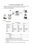
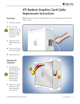
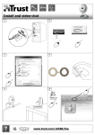
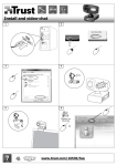
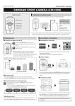
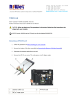
GV-LPR System Installation Guide for Parking
1. Purpose: This Installation guide provides guidelines for installation of the PC side and the field side so that
the system can provide the best performance. The example is an entrance of a car park.
2. GV-LPR System Architecture Diagram:
3. Devices:
3.1 PC Specification:
Specifications
Product Model
GV-LPR-1
GV-LPR-2
GV-LPR-4
GV-LPR-6
Motion mode Motion mode Motion mode IO mode
GV-LPR-8
IO mode
OR IO mode OR IO mode OR IO mode
Number of Ports
1
2
4
6
8
Total FPS
30fps
60fps
120fps
240fps
240fps
FPS / Camera
30fps
30fps
30fps
30fps
30fps
Image Format
JPEG
JPEG
JPEG
JPEG
JPEG
CPU
RAM
HDD
Core 2 Duo
Core 2 Duo
Core 2 Duo
Core 2 Duo Core 2 Duo
E6400 2.13
E6400 2.13
E6600 2.4
E6600 2.4
E6600 2.4
GHz
GHz
GHz
GHz
GHz
512 MB x2
512 MB x2
dual DDR2
dual DDR2
RAM
RAM
250 GB or
250 GB or
250 GB or
250 GB or
250 GB or
above
above
above
above
above
1 GB x2
1 GB x2 dual 1 GB x2 dual
DDR2 RAM
DDR2 RAM
dual
DDR2
RAM
VGA
GeForce
GeForce
GeForce
GeForce
6600 /
6600 /
7300GT /
7300GT /
ATI Radeon
ATI Radeon
ATI Radeon
ATI Radeon
X1550
X1550
X1650
X1650
or above
or above
or above
or above
GeForce
7300GT /
ATI
Radeon
X1650
or above
3.2 GV-LPR software: The GV-LPR software is included in the installation CD. Please install the
version which is suitable for your country.
3.3 GV-LPR video capture card: Each camera provides 30 fps video for better performance.
3.4 GV-NET Card (Needed for I/O Detection Mode): RS232 to RS485 converter. Used to connect
to GV-IO USB box.
3.5 GV-IO USB box (Needed for I/O Detection Mode): It can be connected to detectors to sense
the arrival of vehicles.
3.6 Detector (Needed for I/O Detection Mode): To detect the arrival of vehicles. It should be
connected to GV-IO USB box
Magnetic loop detector
or
Infrared detector
3.7 PC speaker: Can be used to notify guards when the license plates are identified as guest or
when recognition fails.
3.8 Camera and lens: Should provide the function of depressing strong light of the cars. Designed
for LPR usage.
Size of CCD
1/3”” (Min)
Effective picture elements
771x492 (Min)
TV lines of horizontal resolution
480 lines (Min)
S/N ratio
48dB (Min)
Illumination
0.05 LUX (Min)
key features
Depressing strong light, AWB
Auto Electronic Shutter
1/60 ~ 1/100,000 sec
Lens
10 times zoom
3.9 Camera bracket: If the camera is setup at one side of the lane, you should choose the camera
bracket which can be adjusted in 3D freedom so that the image of the license plate can be
adjusted to be horizontal. Otherwise, if the camera is setup at the upper front of the recognition
location, normal camera bracket can be used.
3.10 Camera housing: Camera should be installed inside a camera housing.
3.11 Stand for camera: If the camera is installed in the outdoor, camera stand must be setup to put
the camera.
3.12 Light / LED: Please set up lights if the location is not bright enough. If you want to use
detector to trigger the light, please do not use the same relay output point of the detector to
trigger the recognition because the light may not be fast enough to be lighted when the camera
is going to capture the image. LED illumination is suitable for environment where it is not
permitted to install visible light. LED illumination has to be work with cameras that support LED
illumination.
3.13 Interphone: Please install interphone if the lane is apart from the guard. That would provide
better service for visitors or when recognition fails.
4
Installation:
4.1 Installation of camera and field side:
< 10o
< 30o
< 10o
4.1.1
The location of recognizing is related to the gate. The location of the camera
related to location of the recognizing is very important.
4.1.2
The setup of camera should let the image of the license to be as rectangle as
possible and be horizontal. Camera can be setup as capture from the upper front
of the car or from the side, horizontally in front of the lane. Be careful not to setup
the camera too close to the recognition location. That will cause the license plate
to be not like a rectangle and horizontal. It will lower the recognition rate.
Capture the back license plate is also possible if the first 2 locations just
described is not allowed.
4.1.3
If the camera is setup from the upper front of the recognition location (I/O
location), the angle between the camera and the recognition location should not
greater than 30 degrees. For simplicity, the distance of the camera to the license
plate should be at least 2 times longer from the height of the camera to be setup.
4.1.4
You may use magnetic loop detector or infrared detector to detect the car. If
infrared detector is used, it is advised to use 2 sets of infrared. Set the
recognition actions when 2 of the infrared detect at the same time. That may
prevent from recognizing people passing through the lane. The distance
between the 2 sets of infrared should be 1.5 meters. In this case, if the light of
the location is not bright enough, you may also use the first infrared to trigger the
light if needed.
4.1.5
If the location is not bright enough at night, it is suggested to setup lights so that
the license plate is clear to be captured.
4.1.6
If you are going to trigger the light by using sensor, please take care so that the
light do not let the driver to be uncomfortable when driving.
4.1.7
Please adjust the lens of the camera so that the width of the license plate is in
between 1/3 to 1/5 of the width of the image. Near 1/3 is better if possible.
4.1.8
If the lane is too wide, you may draw a rectangle in yellow color for the drivers to
identify it as a recognition area.
4.1.9
If an interphone is needed, please install it near the gate besides the location of
the driver.
4.2 Installation of PC side:
4.2.1
Install GV-LPR capture card in the PCI slot of the PC.
4.2.2
Install GV-LPR software.
4.2.3
Connect the GV-NET to the RS232 port of the PC.
4.2.4
Connect the GV-IO to GV-NET by using RS485 connection.
4.2.5
Connect GV-RELAY to the GV-IO.
4.2.6
Connect the detector to the to the GV-IO. Please do the corresponding setting in
the GV-LPR software.
4.2.7
Connect the dry relay contact of the gate or light to the GV-RELAY. Please do the
corresponding setting in the GV-LPR software.
4.2.8
After installation of camera and detectors, you may start the GV-LPR software.
4.2.9
If the default license plate size setting is not suitable for your environment,
please perform the Recognition Setup as indicated in the manual. This is a very
important step because it sets the normal height and width of the license plate.
Without correct setting for the license plate may cause the recognition rate to be
low.
4.2.10 If there is more than 1 lane, please perform the Recognition Setup for each of
the lanes.
4.2.11 Drive the car to the planned recognition location to trigger the capture and
recognition of the license plate. The images are stored in the “capture” folder
under the folder GV-LPR is installed and images folders named by date plus
lane number.
4.2.12 You should set the brightness of the image in the GV-LPR software so that the
license plate is clear but not too bright. If the license plate is too bright and let the
number of the license plate to be too thin, it will lower the recognition rate.
Please press the “System Configure” icon and then press the “System
Configuration” and select “Camera” to adjust the “Brightness” and “Contrast” so
that the number is thick enough. If it is an outdoor environment, please be sure
the setting is suitable for most of the weather.
4.2.13 Please setup the information of the cars and their owners in the “Registered
Plates Database”.
4.2.14 For other detail settings, please refer to the user manual.
4.2.15 You may start using the GV-LPR system now.
5
Some points to be take care of:
5.1 If you are going to setup the camera by the side of the lane, be careful that people walks though
may block the view of the license plate.
5.2 If you are going to setup the camera by the side of the lane, it is prefer to set it horizontally and
far enough from the recognition location. Other wise, the license may not be horizontal
rectangle in the image.
5.3 If you are going to capture the license plate from the back of the car, be careful that the license
plate may be too bright when there is a car following it at night with its light is on.
5.4 If the lane is wide enough for 2 directions and infrared is used, be careful of the problem of
wrong trigger that may occur when 2 cars go through at the same time.
5.5 If the system is install in the outdoor, please avoid the direction of East to West to prevent the
influence of the sun light during the sunrise and sunset.
5.6 Blur image will decrease the recognition rate. Please adjust the setting of camera so that the
image is clear. The left image below is blurred. Focus or electronic shutter should be adjusted
so that the image is clear. The right image below is clear.
Blur
Clear
5.7 Italic number will decrease the recognition rate. Please adjust the location of the camera so that
the number of the plate is vertical and not italic. The angle of the camera should be small so that
the number could be vertical. Be careful that most of the back license plates are not placed
vertically.
Italic
Vertical
5.8 Non-horizontal license plate will decrease the recognition rate. Please adjust the angle of the
camera. This is a very important point for the setting.
Non-horizontal
Horizontal