1
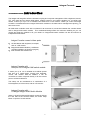
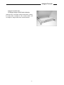
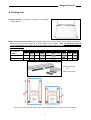
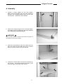
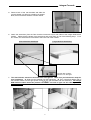
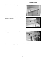
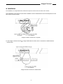
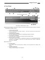
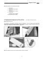
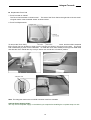
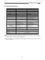
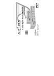
Table of Contents
▓ INTRODUCTION ....................................................................................................1
▓ INTEGRA CONSOLE
Overview ...............................................................................................................3
Features ................................................................................................................3
Packing List ...........................................................................................................4
Assembly...............................................................................................................6
Installation .............................................................................................................9
Front Panel..........................................................................................................10
Replaceable Keyboard and Touch Pad ............................................................... 11
LCD Specification ................................................................................................ 13
Please read this manual thoroughly and follow the Installation procedures to
prevent any damage to the Integra or any connecting device.
Integra Console
------------------------
Introduction
The Integra and IntegraPro offer the ultimate in styling and computer management. With a keyboard, mouse,
TFT LCD panel and an Integra KVM switch module housed in an industry standard 19" 1U-height rack
drawer, it saves you up to 1/3 of valuable real estate from a rack cabinet. Better yet, when the Integra
Console is cascaded with other Integra KVM switch modules to increase server management capacity, you
save even more!
All KVM switch modules come with a universal C-36 connector for connection between the console drawer
and an Integra KVM switch module. This modularized design offers the maximum flexibility, as you can
choose and swap the modules to fit your needs. An Integra KVM switch module can also be used as an
independent KVM switch.
Integra Console comes in three parts
A 1U slide drawer with keyboard, touchpad,
and 15” LCD monitor.
B Integra KVM Switch Module. (15 different
modules available, as shown on page 6)
C Rear bracket and extension kit.
Integra Console with
One-port PS/2 Integra KVM switch module
It saves you up to 1/3 of valuable rack cabinet spaces
and acts as a space-saving console with keyboard,
mouse, and monitor. With an IKM001, it can be
connected to a PS/2 computer directly or to the console
ports of a PS/2 KVM switch.
This setup can be considered as a combination of a
PS/2 keyboard, a PS/2 mouse, and an LCD monitor.
Integra Console with
1U-height Integra KVM Switch Module
When a 1U-height Integra KVM switch module is slid into
the rear side of the console drawer, the entire setup
takes 1U space of a rack-cabinet.
1
Integra Console
Integra Console with
2U-height Integra KVM Switch Module
Attached with a 2U-height Integra KVM switch module,
the setup takes 1U-height for the console drawer and
2U-height for Integra KVM switch module behind it.
2
Integra Console
------------------------
Integra Console
Overview
Three major models of Integra Consoles, HKS10, HKV10, and IKV10, are available with 17” LCD panel, 15”
LCD panel, and 15” LCD panel respectively. These three models share the same accessories (Integra
KVM switch modules and Rear Bracket Kits). The Integra Console is a 19” 1U drawer designed for
applications where space is at a premium, or CRT displays are undesirable. The HKS10 and HKV10 models
support replaceable keyboard and replaceable touch pad.
The drawer can be pulled out for operation from the rack ad latched in the extended position. When not in
use, the display can be folded down, locked and secured while pushed in.
With different Rear bracket & extension kit, the Integra Console can be mounted on rack cabinet of various
depths.
The console comes with standard PS/2 keyboard connector, PS/2 mouse connector and HDB15 VGA
connector for computer or KVM switch connection.
Integra Pro
Model
Keyboard Replaceable
Touch Pad Replaceable
Module Selection
H x W x D (mm)
HKS10
Yes
Yes
Yes
502*445*43.5
HKV10
Yes
Yes
Yes
502*445*43.5
Integra
IKV10
No
No
Yes
485*445*43.5
Features
Modularized KVM switch design.
Integra KVM switch modules are available for PS/2, USB, or Sun interface with 8-or 16-port.
Flip-open 15" or 17” LCD panel supports resolution 1024x768 or 1280x1024 respectively.
For managing computers with PS/2, USB, or Sun interface.
For rack cabinet with depth from 20"(50cm) and up (with appropriate Rear bracket & extension kit).
Standard 19" 1U rack drawer.
Ergonomic hand rest design.
Locking mechanism locks the drawer when pulled out, pushed in, or folded down.
Full 105 key, low-profile, sturdy keyboard included.
Ultra sturdy, tilt-free, two-piece Rear Bracket and Extension design.
Quick and easy installation.
A universal C-36 connector for connection between console drawer and Integra KVM switch module.
Supports Sun keyboard mapping and Mac keyboard mapping.
Optional Built-in -48V/-24V Power Module available.
Extra Features for HKS10 and HKV10
User-replaceable keyboard with various languages support.
User-replaceable touch pad for easy replacement.
Touch pad with simulated wheel control.
3
Integra Console
Packing List
Integra Console: "LCD panel + keyboard + mouse pad"
console drawer
Rear bracket & extension kit: This kit contains two pieces of rear brackets and two pieces of extensions.
Make sure you have the correct kit to fit the depth of your cabinet. Note: the following length is
measured between "front pole and rear pole inside a rack cabinet" not the outside depth of a rack
cabinet enclosure.
Front pole to rear
pole distance
( Depth )
cm
inch
cm
inch
cm
inch
cm
inch
cm
inch
Minimum
49.5
191/2
57.5
225/8
67.5
265/8
77.5
87.5
341/2
Maximum
57
223/8
70.5
273/4
80.5
315/8
90.5
301/2
355/8
100.5
391/2
REK5X
REK6X
REK7X
REK8X
REK9X
REK9X (upper-left)
and
REK5X (lower-right)
Top view of a rack cabinet with Integra KVM2 installed: Depth decides the model number of the REKxX.
4
Integra Console
Integra KVM Switch Module (Please also see another user’s manual for more detail about Integra
KVM Switch module) : Integra KVM switch module box can be connected to an Integra Console or be
used as a stand-alone KVM switch. There are three major categories: PS/2, USB and Sun interfaces.
PS/2 Interface
No. of console port
No. of computer port
KVM switch inside
OSD menu
Height
Cable type
Model Indicator
Type
Model name
Interface
No. of console
port
No. of computer
port
OSD menu
Height
Cable type
Model Indicator
Type
Model name
Interface
IKM001
1
1
No
No
1U
1►1
1
1
1
2
8
16
8
8
Yes
1U
2U
CBMxxxT, CBKxxxT,
CBMxxxUT
1►8 for
1►16 for
USB+PS/2
USB+PS/2
IMM104D
IMM108D
PS/2
IKM2116D
2
16
Yes
Yes
2U
2►16
Sun
ISM108
ISM2208
Sun (mini-DIN8)
Hybrid
IGM108D
IGM116D
PS/2, USB
For computer
No. of console
port
No. of computer
port
OSD menu
Height
Cable type
Model Indicator
Color of computer
port connector
IKM108D
IKM116D
IKM2108D
1
1
2
8
16
8
Yes
Yes
Yes
Yes
Yes
Yes
1U
2U
1U
CBMxxxT or CBKxxxT
1►8
1►16
2►8
No
1U
CBKxxxST
1►8 for
Sun
IMM116D
2►8 for
Sun
Slim
IUM104D
IUM108D
IUM116D
PS/2, USB
PS/2-PC, USB-PC,
USB-Sun, USB-Mac
PS/2-PC
1
1
1
1
1
1
4
8
16
4
8
16
1►4
Yes
1U
CBMxxxH
1►8
1►16
Blue gray
Yes
1U
CBMxxxH, CBMxxxUH
1►4
1►8
1►16
Gray
Optional Built-in -48V/-24V Power Modules are available: IKMP001, IMMP104D,
IMMP108D,IUMP104D, and IUMP108D
Bolt-and-nut set
User's manual
5
Integra Console
Assembly
1.
Choose a proper position for the rack drawer.
Mount the rear brackets (from the Rear bracket &
extension kit), and lightly fasten them onto the rear
vertical poles. Both will be removed later.
2.
Remove the safety stopper from the console drawer.
The safety stopper is designed to prevent the drawer
from sliding out during transportation.
★ WARNING ★
After the safety stopper is removed, the drawer may slide out
when tilted and cause serious injury.
3.
Slide the console drawer to the rack cabinet from the
front and insert the two slide rails of the console
drawer into the pockets of the rear brackets.
4.
Fasten the console drawer onto the front brackets by
four screws. The metal brackets as shown in the
far arrow support rear side of the console.
6
Integra Console
5.
Remove both of the rear brackets and slide the
console drawer out half way to balance its weight.
Now, the front brackets hold the console drawer.
6.
Attach the extensions (from the Rear bracket & extension kit) to both sides of the Integra KVM switch
module. Please note the length of the extensions and mount them in one of the following ways. For a
2U module, the extensions are mounted to the lower half of the module.
Short extensions attachment
Long extensions attachment
The wider side of plastic
extension is on the upper.
7.
The rear brackets, extensions and slide rails have tight fit. Make sure you follow these steps for
easy installation. A. Slide the rear brackets onto the extensions. B. Then, insert both sliding rails of
the console drawer into the tight space formed by the rear brackets and the extensions. The Integra
KVM switch module should be pushed in EVENLY on both of right and left sides by both of
your two hands.
7
Integra Console
8.
Push the rear brackets all the way in and fastens
them.
9.
Slide the console drawer out. Push the Integra KVM
switch module evenly toward the drawer and lock
both units by the screws.
10. Make sure the C-36 connectors are firmly mated
during step 9.
11. Connect the power supply to the power jack on the Integra KVM switch module to complete the
installation.
8
Integra Console
Installation
The installations for Integra KVM switch module with computers can be found in the other user’s manual.
The combination of an Integra console and an IKM001 can be considered as a set of PS/2 keyboard, mouse
and monitor as shown below.
Integra Console connects to a computer
Or, the Integra Console with the 11 Integra KVM switch module can be connected to a KVM switch as
shown below.
Integra Console connects to a KVM switch
9
Integra Console
Front Panel
Front panel of a IKV10 model
Front panel of a HKS10/HKV10 model
KVM Control and Status: (This section is effective only when an Integra KVM switch module is connected,
not applicable for IKM001 module.)
1.
Computer Selection Pad
Press one of these pushbuttons to select a computer. There are no push-buttons for the higher 8 ports
of a 16-port KVM switch.
2.
Selected Computer Indicator
One of the indicators turns red when it corresponding computer is selected.
3.
Local Console in operation
It turns green when a computer is accessed through the Integra Console.
4.
Remote Console in operation
It turns green when a computer is accessed by another set of keyboard/mouse/monitor
connected to the "Remote" console when the Integra KVM switch module is IKM2108D,
IKM2116D, or ISM2208.
LCD Panel Control
5.
LCD Panel Menu
These buttons invoke the OSD menu for settings of the LCD panel as an ordinary LCD
monitor.
6.
LCD Panel Adjustment
Letting you adjust settings for the LCD panel.
10
Integra Console
Keyboard Status & LCD Panel Power Switch
7.
Num Lock
Keyboard Num Lock status.
8.
Caps Lock
Keyboard Caps Lock status.
9.
Scroll Lock
Keyboard Scroll Lock status.
10. LCD Panel Power Switch
Replaceable Keyboard and Touch Pad
(For HKS10 and HKV10 ONLY)
Replaceable Keyboard
The keyboard is replaceable for language change or maintenance. Tilt it up, locate the mini-USB cable
underneath the keyboard and gently unplug it. While installing a keyboard, make sure that you extend just
enough of the cable to keep the keyboard flat inside the tray.
Triangular mark
Note: The triangular mark on the mini-USB connector must face outwards.
11
Integra Console
Replaceable Touch Pad
1. Touch Pad and Its “Wheel”
The Touch Pad simulates a “wheel mouse”. The area of the Touch Pad to the right side of the two small
triangular marks is the simulated “wheel” as shown below.
2. Touch Pad Replacement
To remove the Touch Pad, press the tab underneath it upward to release the latch, and then slide it outwards
till the Touch Pad can be lifted up clear from the notches, as shown in the figure on the right. The Touch
Pad is attached by a piece of mini-USB cable. To install the Touch Pad, extend just enough mini-USB cable
and slide the Touch Pad all the way in till you hear a click sound as it is locked in position.
Triangular mark
Note: The triangular mark on the mini-USB connector must face outwards.
Optional Power Supply Holder
You may secure the power supply on the holder by tie wraps before installing the complete setup to a rack.
12
Integra Console
LCD Panel Specification
Specifications
Active Display Area
Pixel Pitch (mm)
Resolution
Color Pixel Arrangement
Display Mode
Brightness(cd/m^2)
Contrast Ratio
Display Color
User Control
Input Signal
15” LCD Panel
304.1 x 228.1 (mm)
0.297 (H) x 0.297 (V)
1024 x 768 @60/70/75Hz
RGB vertical strip
normally white TN
250(cd/m2)@8mA
350:1
16.7M (8 bits)
OSD Control (auto saving)
RGB analog, H/V separate
Plug-n-Play VESA
Power Consumption
VESA DDC 1/2B
33W typical, normal operation
Viewing Angle
-60~60(H)
-55~45(V) (Typ.)
2 CCFLs
edge-light(top/bottom)
Backlight Unit
Temperature
Operating
Storage (Shipping)
Operating Humidity
Non-Operating Humidity
Power Supply Input
Voltage
Power Supply Input
Frequency
Approval
17” LCD Panel
337.920 x 270.336 (mm)
0.264 (per one triad) x 0.264
1280 x 1024
R.G.B. Vertical Stripe
Normally White
260 (center) @ 7mA
450:1 (Typ)
262K colors (RGB 6-bits data)
OSD Control
Even/Odd R/G/B data,
ey sync signal, Clock
VESA DDC 1/2B
25W typical,
(w/o Inverter, All black pattern)
-80~80(H)
-80~80(V) (Typ.)
4 CCFLs
edge-light(top/bottom)
0 to +50 (˚ C)
0 to +50 (˚ C)
-20 to +60 (˚ C)
-20 to +60 (˚ C)
Relative Humidity 8% ~ 95%
Relative Humidity ≦95%
(Ta ≦40˚ C)
90% RH
95% RH
Full range, 100V AC to 240V AC
47 Hz ~ 63 Hz
CE, FCC for the product. UL, TUV, CE for power supply
Note:
1) For optimum video performance, VGA resolution should be set to 1024 x 768 for 15” LCD panel and be
set to 1280 x 1024 for 17” LCD panel with low refresh rate.
2) If part of the display is not clear, please activate “Auto Adjust” for the LCD monitor using the four “LCD
Panel Control” buttons.
13
Integra Console
Limited Warranty
IN NO EVENT SHALL THE DIRECT VENDOR'S LIABILITY FOR DIRECT OR INDIRECT, SPECIAL, INCIDENTIAL OR CONSEQUENTIAL
DAMAGES, LOSS OF PROFIT, LOSS OF BUSINESS, OR FINANCIAL LOSS WHICH MAY BE CAUSED BY THE USE OF THE PRODUCT
EXCEEDS THE PRICE PAID FOR THE PDOCUDT.
The direct vendor makes no warranty or representation, expressed or implied with respect to the contents or use of this documentation, and
especially disclaims its quality, performance, merchantability, or fitness for any particular purpose.
The direct vendor also reserves the right to revise or update the product or documentation without obligation to notify any user of such revisions
or updates. For further information, please contact your direct vendor.
All the brand names and registered trademarks are the property of their respective owners.
PP5-IK000-400
14