1
TABLE OF CONTENTS
Introduction . . . . . . . . . . . . . . . . . . . . . . . . . . . . . . . . . . . . . . . . . . . . . . . . . . . . . . . . . . . . . . . . . . . . . . . . . . . . . . . . . . . . . . . . . . . 3
Registration . . . . . . . . . . . . . . . . . . . . . . . . . . . . . . . . . . . . . . . . . . . . . . . . . . . . . . . . . . . . . . . . . . . . . . . . . . . . . . . . . . . . . . . . . . . . 3
Features . . . . . . . . . . . . . . . . . . . . . . . . . . . . . . . . . . . . . . . . . . . . . . . . . . . . . . . . . . . . . . . . . . . . . . . . . . . . . . . . . . . . . . . . . . . . . . . 3
Overview . . . . . . . . . . . . . . . . . . . . . . . . . . . . . . . . . . . . . . . . . . . . . . . . . . . . . . . . . . . . . . . . . . . . . . . . . . . . . . . . . . . . . . . . . . . . . . 4
Setting Up . . . . . . . . . . . . . . . . . . . . . . . . . . . . . . . . . . . . . . . . . . . . . . . . . . . . . . . . . . . . . . . . . . . . . . . . . . . . . . . . . . . . . . . . . . . . . 5
Unpacking . . . . . . . . . . . . . . . . . . . . . . . . . . . . . . . . . . . . . . . . . . . . . . . . . . . . . . . . . . . . . . . . . . . . . . . . . . . . . . . . . . . . . . . . 4
AC Power Hookup. . . . . . . . . . . . . . . . . . . . . . . . . . . . . . . . . . . . . . . . . . . . . . . . . . . . . . . . . . . . . . . . . . . . . . . . . . . . . . . . . . 4
Audio Connections . . . . . . . . . . . . . . . . . . . . . . . . . . . . . . . . . . . . . . . . . . . . . . . . . . . . . . . . . . . . . . . . . . . . . . . . . . . . . . . . . 4
Installation . . . . . . . . . . . . . . . . . . . . . . . . . . . . . . . . . . . . . . . . . . . . . . . . . . . . . . . . . . . . . . . . . . . . . . . . . . . . . . . . . . . . . . . . 5
Safety Precautions . . . . . . . . . . . . . . . . . . . . . . . . . . . . . . . . . . . . . . . . . . . . . . . . . . . . . . . . . . . . . . . . . . . . . . . . . . . . . . . . . . . . . . . 5
Powering Up . . . . . . . . . . . . . . . . . . . . . . . . . . . . . . . . . . . . . . . . . . . . . . . . . . . . . . . . . . . . . . . . . . . . . . . . . . . . . . . . . . . . . . . . . . . 5
Front-Panel Controls & Indicators. . . . . . . . . . . . . . . . . . . . . . . . . . . . . . . . . . . . . . . . . . . . . . . . . . . . . . . . . . . . . . . . . . . . . . . . . . . 6
Power Switch . . . . . . . . . . . . . . . . . . . . . . . . . . . . . . . . . . . . . . . . . . . . . . . . . . . . . . . . . . . . . . . . . . . . . . . . . . . . . . . . . . . . . . 6
Bypass Switch. . . . . . . . . . . . . . . . . . . . . . . . . . . . . . . . . . . . . . . . . . . . . . . . . . . . . . . . . . . . . . . . . . . . . . . . . . . . . . . . . . . . . . 6
The Key Filter Network (Key Listen, Source, Freq, And Key Filter Control) . . . . . . . . . . . . . . . . . . . . . . . . . . . . . . . . . . . . . . 6
Key Listen Switch. . . . . . . . . . . . . . . . . . . . . . . . . . . . . . . . . . . . . . . . . . . . . . . . . . . . . . . . . . . . . . . . . . . . . . . . . . . . . . . . . . . 6
Source (Key Filter) Switch . . . . . . . . . . . . . . . . . . . . . . . . . . . . . . . . . . . . . . . . . . . . . . . . . . . . . . . . . . . . . . . . . . . . . . . . . . . . 6
Freq (Key Filter) Switch . . . . . . . . . . . . . . . . . . . . . . . . . . . . . . . . . . . . . . . . . . . . . . . . . . . . . . . . . . . . . . . . . . . . . . . . . . . . . . 7
Gate Closed LEDs 1-8 . . . . . . . . . . . . . . . . . . . . . . . . . . . . . . . . . . . . . . . . . . . . . . . . . . . . . . . . . . . . . . . . . . . . . . . . . . . . . . . 7
Channel Selected LEDs 1-8 . . . . . . . . . . . . . . . . . . . . . . . . . . . . . . . . . . . . . . . . . . . . . . . . . . . . . . . . . . . . . . . . . . . . . . . . . . . 7
Channel-Select 1-8. . . . . . . . . . . . . . . . . . . . . . . . . . . . . . . . . . . . . . . . . . . . . . . . . . . . . . . . . . . . . . . . . . . . . . . . . . . . . . . . . . 7
LCD Window . . . . . . . . . . . . . . . . . . . . . . . . . . . . . . . . . . . . . . . . . . . . . . . . . . . . . . . . . . . . . . . . . . . . . . . . . . . . . . . . . . . . . 7
Control Knobs . . . . . . . . . . . . . . . . . . . . . . . . . . . . . . . . . . . . . . . . . . . . . . . . . . . . . . . . . . . . . . . . . . . . . . . . . . . . . . . . . . . . . 8
Key Filter . . . . . . . . . . . . . . . . . . . . . . . . . . . . . . . . . . . . . . . . . . . . . . . . . . . . . . . . . . . . . . . . . . . . . . . . . . . . . . . . . . . . . 8
Threshold . . . . . . . . . . . . . . . . . . . . . . . . . . . . . . . . . . . . . . . . . . . . . . . . . . . . . . . . . . . . . . . . . . . . . . . . . . . . . . . . . . . . . 8
Attack . . . . . . . . . . . . . . . . . . . . . . . . . . . . . . . . . . . . . . . . . . . . . . . . . . . . . . . . . . . . . . . . . . . . . . . . . . . . . . . . . . . . . . . . 8
Hold . . . . . . . . . . . . . . . . . . . . . . . . . . . . . . . . . . . . . . . . . . . . . . . . . . . . . . . . . . . . . . . . . . . . . . . . . . . . . . . . . . . . . . . . . 8
Release . . . . . . . . . . . . . . . . . . . . . . . . . . . . . . . . . . . . . . . . . . . . . . . . . . . . . . . . . . . . . . . . . . . . . . . . . . . . . . . . . . . . . . . 9
Range . . . . . . . . . . . . . . . . . . . . . . . . . . . . . . . . . . . . . . . . . . . . . . . . . . . . . . . . . . . . . . . . . . . . . . . . . . . . . . . . . . . . . . . . 9
Rotary Encoder. . . . . . . . . . . . . . . . . . . . . . . . . . . . . . . . . . . . . . . . . . . . . . . . . . . . . . . . . . . . . . . . . . . . . . . . . . . . . . . . . 9
Menu & Select Switches . . . . . . . . . . . . . . . . . . . . . . . . . . . . . . . . . . . . . . . . . . . . . . . . . . . . . . . . . . . . . . . . . . . . . . . . . . 9
Rear-Panel Connections. . . . . . . . . . . . . . . . . . . . . . . . . . . . . . . . . . . . . . . . . . . . . . . . . . . . . . . . . . . . . . . . . . . . . . . . . . . . . . . . . . 10
Input 1-8 . . . . . . . . . . . . . . . . . . . . . . . . . . . . . . . . . . . . . . . . . . . . . . . . . . . . . . . . . . . . . . . . . . . . . . . . . . . . . . . . . . . . . . . . 10
Output 1-8 . . . . . . . . . . . . . . . . . . . . . . . . . . . . . . . . . . . . . . . . . . . . . . . . . . . . . . . . . . . . . . . . . . . . . . . . . . . . . . . . . . . . . . 11
Key 1-8 . . . . . . . . . . . . . . . . . . . . . . . . . . . . . . . . . . . . . . . . . . . . . . . . . . . . . . . . . . . . . . . . . . . . . . . . . . . . . . . . . . . . . . . . . 11
Non-Destructive Key Listen Audition . . . . . . . . . . . . . . . . . . . . . . . . . . . . . . . . . . . . . . . . . . . . . . . . . . . . . . . . . . . . . . . . . . 12
MIDI In, MIDI Out, MIDI Thru . . . . . . . . . . . . . . . . . . . . . . . . . . . . . . . . . . . . . . . . . . . . . . . . . . . . . . . . . . . . . . . . . . . . . 12
Tutorial For Using The Pro Gate . . . . . . . . . . . . . . . . . . . . . . . . . . . . . . . . . . . . . . . . . . . . . . . . . . . . . . . . . . . . . . . . . . . . . . . . . . . 13
Getting Started. . . . . . . . . . . . . . . . . . . . . . . . . . . . . . . . . . . . . . . . . . . . . . . . . . . . . . . . . . . . . . . . . . . . . . . . . . . . . . . . . . . . 13
1
Channel Select . . . . . . . . . . . . . . . . . . . . . . . . . . . . . . . . . . . . . . . . . . . . . . . . . . . . . . . . . . . . . . . . . . . . . . . . . . . . . . . . . . . . 13
Bypass . . . . . . . . . . . . . . . . . . . . . . . . . . . . . . . . . . . . . . . . . . . . . . . . . . . . . . . . . . . . . . . . . . . . . . . . . . . . . . . . . . . . . . . . . . 14
Key Listen . . . . . . . . . . . . . . . . . . . . . . . . . . . . . . . . . . . . . . . . . . . . . . . . . . . . . . . . . . . . . . . . . . . . . . . . . . . . . . . . . . . . . . . 14
Source . . . . . . . . . . . . . . . . . . . . . . . . . . . . . . . . . . . . . . . . . . . . . . . . . . . . . . . . . . . . . . . . . . . . . . . . . . . . . . . . . . . . . . . . . . 14
Freq . . . . . . . . . . . . . . . . . . . . . . . . . . . . . . . . . . . . . . . . . . . . . . . . . . . . . . . . . . . . . . . . . . . . . . . . . . . . . . . . . . . . . . . . . . . . 15
Using The Rotary Encoder For Key Source, Link, Bypass, Song Functions. . . . . . . . . . . . . . . . . . . . . . . . . . . . . . . . . . . . . . . 15
Key Source . . . . . . . . . . . . . . . . . . . . . . . . . . . . . . . . . . . . . . . . . . . . . . . . . . . . . . . . . . . . . . . . . . . . . . . . . . . . . . . . . . . 15
Link . . . . . . . . . . . . . . . . . . . . . . . . . . . . . . . . . . . . . . . . . . . . . . . . . . . . . . . . . . . . . . . . . . . . . . . . . . . . . . . . . . . . . . . . 16
Bypass. . . . . . . . . . . . . . . . . . . . . . . . . . . . . . . . . . . . . . . . . . . . . . . . . . . . . . . . . . . . . . . . . . . . . . . . . . . . . . . . . . . . . . . 16
Song Screeen Overview. . . . . . . . . . . . . . . . . . . . . . . . . . . . . . . . . . . . . . . . . . . . . . . . . . . . . . . . . . . . . . . . . . . . . . . . . . 17
Editing Mode (Channel, System, MIDI) . . . . . . . . . . . . . . . . . . . . . . . . . . . . . . . . . . . . . . . . . . . . . . . . . . . . . . . . . . . . . . . . . . . . . 17
Editing Mode Directory . . . . . . . . . . . . . . . . . . . . . . . . . . . . . . . . . . . . . . . . . . . . . . . . . . . . . . . . . . . . . . . . . . . . . . . . . . . . . 18
Next & Back Functions . . . . . . . . . . . . . . . . . . . . . . . . . . . . . . . . . . . . . . . . . . . . . . . . . . . . . . . . . . . . . . . . . . . . . . . . . . . . . 18
Channel Edit Functions . . . . . . . . . . . . . . . . . . . . . . . . . . . . . . . . . . . . . . . . . . . . . . . . . . . . . . . . . . . . . . . . . . . . . . . . . . . . . 19
System Editing Functions. . . . . . . . . . . . . . . . . . . . . . . . . . . . . . . . . . . . . . . . . . . . . . . . . . . . . . . . . . . . . . . . . . . . . . . . . . . . 22
MIDI Editing Functions . . . . . . . . . . . . . . . . . . . . . . . . . . . . . . . . . . . . . . . . . . . . . . . . . . . . . . . . . . . . . . . . . . . . . . . . . . . . 25
Cables & Connectors. . . . . . . . . . . . . . . . . . . . . . . . . . . . . . . . . . . . . . . . . . . . . . . . . . . . . . . . . . . . . . . . . . . . . . . . . . . . . . . . . . . . 28
Pro Gate Applications & Setup Diagrams . . . . . . . . . . . . . . . . . . . . . . . . . . . . . . . . . . . . . . . . . . . . . . . . . . . . . . . . . . . . . . . . . . . . 29
Using The Pro Gate With A Mixer, A Multi-Track Recorder, And A Mix-Down Recorder . . . . . . . . . . . . . . . . . . . . . . . . . . . 29
Simple Gating To Control Noise & Isolate Instruments . . . . . . . . . . . . . . . . . . . . . . . . . . . . . . . . . . . . . . . . . . . . . . . . . . . . . 30
Keying From A Second Source . . . . . . . . . . . . . . . . . . . . . . . . . . . . . . . . . . . . . . . . . . . . . . . . . . . . . . . . . . . . . . . . . . . . . . . . 32
Using The Non-Destructive Key Listen Audition . . . . . . . . . . . . . . . . . . . . . . . . . . . . . . . . . . . . . . . . . . . . . . . . . . . . . . . . . . 34
Reshaping Samples. . . . . . . . . . . . . . . . . . . . . . . . . . . . . . . . . . . . . . . . . . . . . . . . . . . . . . . . . . . . . . . . . . . . . . . . . . . . . . . . . 35
Chopping Sounds . . . . . . . . . . . . . . . . . . . . . . . . . . . . . . . . . . . . . . . . . . . . . . . . . . . . . . . . . . . . . . . . . . . . . . . . . . . . . . . . . 36
Frequency-Selective Gating . . . . . . . . . . . . . . . . . . . . . . . . . . . . . . . . . . . . . . . . . . . . . . . . . . . . . . . . . . . . . . . . . . . . . . . . . . 37
Gating Reverb . . . . . . . . . . . . . . . . . . . . . . . . . . . . . . . . . . . . . . . . . . . . . . . . . . . . . . . . . . . . . . . . . . . . . . . . . . . . . . . . . . . . 37
Keying Non-Adjacent Channels From A Single Source . . . . . . . . . . . . . . . . . . . . . . . . . . . . . . . . . . . . . . . . . . . . . . . . . . . . . 38
Using MIDI To Control Gates & Dump Data. . . . . . . . . . . . . . . . . . . . . . . . . . . . . . . . . . . . . . . . . . . . . . . . . . . . . . . . . . . . 39
Using MIDI With The Pro Gate . . . . . . . . . . . . . . . . . . . . . . . . . . . . . . . . . . . . . . . . . . . . . . . . . . . . . . . . . . . . . . . . . . . . . . . . . . . 40
MIDI Controllers & Numbers. . . . . . . . . . . . . . . . . . . . . . . . . . . . . . . . . . . . . . . . . . . . . . . . . . . . . . . . . . . . . . . . . . . . . . . . 40
The MIDI Program Table (MPT) . . . . . . . . . . . . . . . . . . . . . . . . . . . . . . . . . . . . . . . . . . . . . . . . . . . . . . . . . . . . . . . . . . . . . 41
Loading Data From A Remote Source . . . . . . . . . . . . . . . . . . . . . . . . . . . . . . . . . . . . . . . . . . . . . . . . . . . . . . . . . . . . . . . . . . 41
MIDI Implementation In The Pro Gate . . . . . . . . . . . . . . . . . . . . . . . . . . . . . . . . . . . . . . . . . . . . . . . . . . . . . . . . . . . . . . . . . . . . . 41
Channel Voice Messages. . . . . . . . . . . . . . . . . . . . . . . . . . . . . . . . . . . . . . . . . . . . . . . . . . . . . . . . . . . . . . . . . . . . . . . . . . . . . 41
Program Change . . . . . . . . . . . . . . . . . . . . . . . . . . . . . . . . . . . . . . . . . . . . . . . . . . . . . . . . . . . . . . . . . . . . . . . . . . . . . . . . . . 41
Channel Mode Messages . . . . . . . . . . . . . . . . . . . . . . . . . . . . . . . . . . . . . . . . . . . . . . . . . . . . . . . . . . . . . . . . . . . . . . . . . . . . 41
System Exclusive (SysEx) Messages. . . . . . . . . . . . . . . . . . . . . . . . . . . . . . . . . . . . . . . . . . . . . . . . . . . . . . . . . . . . . . . . . . . . . 41
Other MIDI Notes. . . . . . . . . . . . . . . . . . . . . . . . . . . . . . . . . . . . . . . . . . . . . . . . . . . . . . . . . . . . . . . . . . . . . . . . . . . . . . . . . 42
MIDI Note Chart . . . . . . . . . . . . . . . . . . . . . . . . . . . . . . . . . . . . . . . . . . . . . . . . . . . . . . . . . . . . . . . . . . . . . . . . . . . . . . . . . . . . . . 43
Troubleshooting. . . . . . . . . . . . . . . . . . . . . . . . . . . . . . . . . . . . . . . . . . . . . . . . . . . . . . . . . . . . . . . . . . . . . . . . . . . . . . . . . . . . . . . . 44
Factory Reset . . . . . . . . . . . . . . . . . . . . . . . . . . . . . . . . . . . . . . . . . . . . . . . . . . . . . . . . . . . . . . . . . . . . . . . . . . . . . . . . . . . . . 44
Internal Battery Replacement . . . . . . . . . . . . . . . . . . . . . . . . . . . . . . . . . . . . . . . . . . . . . . . . . . . . . . . . . . . . . . . . . . . . . . . . . 44
Warranty Information . . . . . . . . . . . . . . . . . . . . . . . . . . . . . . . . . . . . . . . . . . . . . . . . . . . . . . . . . . . . . . . . . . . . . . . . . . . . . . . . . . . 45
Service Information . . . . . . . . . . . . . . . . . . . . . . . . . . . . . . . . . . . . . . . . . . . . . . . . . . . . . . . . . . . . . . . . . . . . . . . . . . . . . . . . . . . . . 46
ART Pro Gate Specifications . . . . . . . . . . . . . . . . . . . . . . . . . . . . . . . . . . . . . . . . . . . . . . . . . . . . . . . . . . . . . . . . . . . . . . . . . . . . . . 47
Functional Diagram Of The ART Pro Gate . . . . . . . . . . . . . . . . . . . . . . . . . . . . . . . . . . . . . . . . . . . . . . . . . . . . . . . . . . . . . . . . . . . 48
205-5004-101
2
Introduction
Thank you for purchasing the Applied Research and Technology Pro Gate professional eight-channel programmable noise gate. The
Pro Gate is a professional tool designed to work seamlessly in any live sound or digital or analog recording situation. Please refer to
this manual for long, continuous use of your Pro Gate.
Registration
If you haven’t done so already, please take the time to fill out the User Registration Card for your purchase. Having you in our data
base allows us to keep you informed of updates, application notes, and new product introductions. It only takes a moment and will
ensure you are constantly up to date with your purchase.
Fill in the following for your reference:
DATE OF PURCHASE:
.
PURCHASED FROM:
.
SERIAL NUMBER:
.
Features
The Pro Gate is one of the finest noise gates, and the only full-featured 8-channel noise gate, available. Containing eight separate
noise gates that can be used separately or linked in pairs or groups, the Pro Gate is one of the most versatile signal processors for
keeping your onstage and recorded mixes quiet. Complete programmability with a unique, easy-to-use interface allows you to set gating parameters and save them in 20 Songs (each containing the information for all eight gates simultaneously) for later recall. Its
extensive MIDI capabilities let you transfer the Pro Gate’s data to other Pro Gates, sequencers, etc., plus it allows real-time control
over gating parameters. The Pro Gate is designed and constructed with the absolute best components, assuring that it won’t add any
noise. The Pro Gate offers:
• Eight independent, fully programmable noise gates
• Half the space and cost of comparable quality gates
• Internal, external, and MIDI key sources
• Automatic storing of gate settings
• Balanced 1/4" TRS inputs and outputs
• Unbalanced 1/4" external key inputs
• Independent relay bypass on each channel
• Revolutionary user interface
• Completely digitized front panel
• MIDI real-time control of parameters
• Sends MIDI Note On, Note Off messages for triggering external sound sources
• Rugged, reinforced steel-and-aluminum chassis
• 5-year warranty
• Designed and manufactured in the USA
The Pro Gate is part of ART’s Reference Series.
3
OVERVIEW
The Pro Gate is a multi-purpose tool for audio engineering and recording. Enclosed in a 2U (3.5" high) rack-mountable chassis are
eight independent channels of analog noise gating designed to work seamlessly with any recording, sound-reinforcement, or electronic instrument setup. The revolutionary front-panel interface allows you to assign the front panel to any of eight channels with the
press of a button. Changes made to any of the eight channels are instantly stored when another channel is selected. In addition, channels can be named (for example, Snare, Vocal, Kick, etc.), for easy identification.
The Pro Gate operates like any standard, single- or dual-channel professional noise gate you may have worked with. Six encoders are
laid out in typical analog fashion to control tunable high-pass and low-pass filters (HPF and LPF), Threshold, Attack, Release, Hold
time, and Range. Values for all these parameters are displayed in a 40 x 2 LCD display located directly above the controls. When a
knob is turned, the change in value is instantly indicated. Audio connections are 1/4" balanced TRS, and external key inputs are 1/4"
unbalanced TS. Each channel contains a bypass relay that allows signal to pass when power is interrupted.
Having separate controls for each channel allows for the ultimate in flexibility. Each channel of the Pro Gate may be used as an independent gate, or channels may be linked so that the channels’ gates may be opened by a single “key” source.
SETTING UP
Unpacking
Your Pro Gate was packed with care at the factory. The shipping carton was designed to protect it during initial shipment. Please
retain this carton for use in transporting the Pro Gate when it is not installed in a rack, or in the unlikely event that you need to
return your Pro Gate for servicing.
The shipping carton should contain:
• Pro Gate with same serial number as shown on shipping carton.
• The owner’s manual.
• User Registration Card.
AC Power Hookup
The Pro Gate has an internal power supply designed to operate at 115 Volts AC, 50 to 60 Hz. Units manufactured for use outside
the United States of America have been modified to comply with the required electrical specifications. Under no circumstances
should the power cable be altered. If the cable becomes cut or damaged, discontinue its use and have it replaced before operating the
Pro Gate.
Audio Connections
All audio connections to and from the Pro Gate (except the Non-Destructive Key Listen Audition output) are 1/4" balanced TRS
(Tip = Hot, Ring = Cold, Sleeve = Ground). All connections for keying are 1/4" unbalanced. We recommend using only high-quality
shielded cables equipped with high-quality connectors. The Pro Gate may be employed in unbalanced systems by using standard
cables equipped with 1/4" phone jacks. Refer to page 24 for information on setting the System I/O for balanced and unbalanced
operation. For connections using other plug types, see page 28.
4
Installation
The Pro Gate may be employed in a number of setups including:
• Between a mixer and a modular digital multi-track recorder, DAT machine, or analog recorder.
• In a mixer’s channel insert points.
• Between signal processors and mixers or instrument amplifiers.
• Between electronic musical instruments (such as synthesizers, samplers, etc.) and down-line gear.
Note: The Pro Gate should be securely mounted in a standard 19" rack.
SAFETY PRECAUTIONS
Warning: To avoid the risk of shock or fire, do not expose this unit to moisture. Do not remove metal covers from
chassis parts. Removing the chassis from its cabinet exposes extremely dangerous high voltages. There are no userserviceable parts inside. Hazardous voltages are present inside the chassis. Refer all servicing to qualified personnel.
Caution: If your line cord (mains supply) becomes damaged and must be replaced, always replace it with the
proper type.
POWERING UP
When the power switch is turned on, the red LEDs blink on and off for four seconds while the Pro Gate runs an internal diagnostic
check. The software version is indicated in the LCD window at the same time. After four seconds, the unit is ready for use. The Pro
Gate will power up as it was left at power down. For example: If you disconnect the power or turn the Pro Gate off while Channel 4’s
parameters are displayed, the Pro Gate will power up with Channel 4 selected.
When you turn on the Pro Gate, you may hear the internal relays click as they engage (they do this every time the power is turned on
or off ). This is normal. The Pro Gate is designed so that signal is allowed to pass directly through the unit by way of the relays if the
power is inadvertently turned off or disconnected. These relays are also used in the Pro Gate’s Bypass modes, assuring the best-quality
audio signal, whether the Pro Gate is on or off.
If the Pro Gate does not follow the checkout sequence (even though the power is on, as indicated by some or all LEDs glowing), try
performing a Factory Reset, as indicated on page 44.
Note: A Factory Reset will return all settings in all Songs to their factory default values. Once you have reset the unit, any customized
settings are permanently lost.
If the unit still does not operate properly, turn it off and unplug it. Then consult your dealer or ART Customer Service.
5
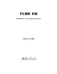
FRONT-PANEL CONTROLS & INDICATORS
GATE CLOSED
CHANNEL SELECTED
Hz
dB
Milliseconds
Milliseconds
Milliseconds
dB
With the exception of the Power switch, which operates independently, all controls are arranged in groups by function.
Power Switch
The Power switch supplies and removes power from the unit; the Gate Closed LEDs, one of the
Channel Selected LEDs, and the LCD display window are all illuminated when the power is applied.
If the unit does not turn on when the switch is toggled, check the AC (Mains) power cord. Also make
sure that the outlet that it is plugged into is “live,” by plugging in another piece of equipment that
you know works (try plugging into another outlet, too). If the outlet is good but the Pro Gate does
not turn on, consult your dealer or ART Customer Service.
Bypass
When a channel is bypassed, that channel’s input signal is routed directly to its output jack via a relay.
This assures the cleanest signal path, with virtually no signal loss. The Bypass remains independent for
linked channels. That is, even if the gating functions of two or more channels are linked, the
active/bypass state for each channel remains independent.
The Key Filter Network (Key Listen, Source, Freq, And Key Filter Control)
Any professional who has used a noise gate will tell you that the most important feature is the tunable key filter. This is an equalizer
included in front of the gate for the purpose of “tuning” that gate to open only when it “hears” a specific frequency. For example:
when miking a drum kit, you can tune the gate for the snare drum so that it doesn’t open when the drummer hits the hi-hat, and
vise-versa. This is a necessity when working with drums, live sessions (in the studio or live onstage), multiple vocalists, or in any situation where you have multiple instruments in the same area.
Key Listen
The Pro Gate allows you to listen to the Key while setting up a channel. Press the Key Listen button. You will see the word Listen in
the top row of the LCD display window, and the red Channel Selected LED for that channel will blink continuously. Pressing Key
Listen or any of the eight Channel Select buttons deactivates the Key Listen function (indicated by the word Listen disappearing, and
the Channel Selected LED glowing continuously).
Note: If the channel is in Bypass mode, the word Bypass will be replaced in the LCD display window by the word Listen, and the key
will be heard at the channel’s output; however, the channel remains in Bypass mode. Also, if you turn the Rotary Encoder or press
either Menu or Select, Listen mode is unaffected, and the channel’s Channel Selected LED will continue to blink to remind you that
the channel is in Key Listen mode.
Source (Key Filter)
The Source button selects whether a channel’s gate is triggered internally (by the signal entering the channel’s input and passing
through the Key filter network), externally (by the signal entering the channel’s external Key input jack), or via MIDI. Internal keying is the default value set at the factory. To check which key is active for a channel, choose a channel using one of the eight Channel
6
Select buttons, and then press the Source button. You will see Int., Ext., or MIDI in the top row of the LCD
display window. It disappears 4 seconds after your last selection has been made. To check a channel’s keying,
push Source once and the currently selected channel’s key status will be indicated for 4 seconds. For information on changing the Key source, see pages 14 and 15.
Freq (Key Filter)
Each channel’s internal key has two filters, a low-pass (LPF) and high-pass (HPF), which allows you to tailor
the frequency response range of the key to exclude unwanted frequencies so that they do not trigger a channel’s gate. Each time you press the Freq key, you’ll see the far left portion of the LCD window change
between “LPF” and “HPF.” The current value for each filter is shown below HPF or LPF. Turning the Key
Filter knob below the display adjusts the filter’s cutoff frequency.
Note: A high-pass filter allows frequencies above its cutoff frequency to pass, removing frequencies below that point. A low-pass filter
acts in the opposite way, allowing frequencies below the cutoff point to pass through, while removing frequencies above the cutoff.
Gate Closed LEDs 1-8
Each of the Pro Gate’s eight gates has a green LED indicator that glows
when the corresponding gate is closed. Whenever a gate is open, its
LED goes dark.
GATE CLOSED
Channel Selected LEDs 1-8
When a Channel is selected via a Channel Select button, its corresponding red LED glows. At the same time, the LCD Window’s information changes to show the settings of the current channel.
CHANNEL SELECTED
Channel Select 1-8
The Channel Select buttons are used to choose which channel the
front-panel controls are assigned to. All front-panel controls, buttons,
and “channel editing” are designated to the channel selected. Each
Channel Select button has its own corresponding red Channel Selected
LED above it that tells you when a channel is selected.
LCD Window
The 40x2 character display is illuminated so that you can read it,
regardless of external lighting conditions. Its viewing angle can be
optimized via the Pro Gate’s software (see page 25).
Hz
dB
Milliseconds
Milliseconds
Milliseconds
dB
7
CONTROL KNOBS
Key Filter
The Pro Gate’s Key Filter includes a 26-position high-pass filter (HPF) covering a range from 25Hz
to 2200Hz, and a 26-position low-pass filter (LPF) covering a range from 250Hz to 20kHz. The
Key Filter acts on signals coming from the channel’s Input or Key jacks.
Hz
dB
LPF values (default = 20K): 250, 320, 350, 450, 500, 630, 710, 790, 1000, 1100, 1300, 1600,
1800, 2800, 3200, 4000, 5000, 5700, 6300, 8000, 9000, 10K, 13K, 14K, 16K, 20K
HPF values (default = 25 Hz): 25, 31, 35, 44, 50, 63, 70, 90, 100, 130, 140, 180, 200, 250, 310,
400, 500, 560, 710, 790, 1000, 1100, 1300, 1600, 1800, 2200
Threshold
The Threshold control sets the level at which the gate opens and closes. When a signal’s intensity is
lower than the threshold point, the gate remains closed (the green Gate Closed LED for that channel glows continuously). When the signal strength exceeds the threshold, the gate opens (its LED goes dark while the gate is open).
The Pro Gate’s 67 threshold levels are indicated in decibels (dB).
Threshold values (default = -20): -50, -49, -48, -47, -46, -45, -44, -43, -42, -41, -40, -39, -38, -37, -36, -35, -34, -33, -32, -31, -30,
-29, -28, -27, -26, -25, -24, -23, -22, -21, -20, -19, -18, -17, -16, -15, -14, -13, -12, -11, -10, -9, -8, -7, -6, -5, -4, -3, -2, -1, 0, 1, 2,
3, 4, 5, 6, 7, 8, 9, 10, 11, 12, 13, 14, 15, 16
Attack
The Attack control sets the amount of time it takes for the gate to open once it is triggered. Faster
attack times are ideal for drums and other percussive instruments, whereas slower times are better
suited to vocals, strings, and special effects. The Pro Gate’s 75 attack times are indicated in milliseconds (thousandths of a second) or microseconds (µS, ten-thousandths of a second).
Milliseconds
Milliseconds
Attack values (default = 0.63): 20µS, 28µS, 32µS, 35µS, 45µS, 50µS, 63µS, 71µS, 89µS, 0.10, 0.13,
0.14, 0.18, 0.22, 0.25, 0.28, 0.35, 0.40, 0.50, 0.56, 0.63, 0.71, 0.89, 1.0, 1.1, 1.3, 1.6, 1.8, 2.0, 2.2,
2.8, 3.2, 3.5, 4.0, 4.5, 5.0, 5.6, 6.3, 7.1, 8.9, 10, 11, 13, 14, 16, 18, 20, 22, 25, 28, 32, 35, 40, 45,
50, 56, 63, 71, 79, 89, 100, 110, 130, 140, 160, 180, 200, 220, 250, 280, 320, 350, 400, 450, 500
Hold
The Hold control governs the length of time the gate is open. The Pro Gate’s 69 Hold times are
indicated in milliseconds (thousandths of a second).
Hold values (default = 50): 4, 5, 6, 7, 8, 9, 10, 11, 13, 14, 16, 18, 20, 22, 25, 28, 32, 36, 40, 45, 50, 57, 63, 71, 80, 90, 100, 110,
130, 140, 160, 180, 200, 220, 250, 280, 320, 360, 400, 450, 500, 570, 630, 710, 800, 900, 1000, 1100, 1300, 1400, 1600, 1800,
2000, 2200, 2500, 2800, 3200, 3600, 4000
8
Release
The Release time is after the Hold time (total gate-open time is additive; that is, Hold time + Release
time = gate open to gate closed time). The Release control sets how long it takes for the gate to close.
Faster (smaller) values can be useful in providing a more staccato sound, while slower release times are
useful for most musical instruments and vocals. Unless a special effect is required, the release time is
usually set so that the natural decay time of the sound is not cut off by the gate closing too soon. The
Pro Gate’s 60 release times are indicated in milliseconds (thousandths of a second).
Milliseconds
dB
Release values (default = 22): 3, 4, 5, 6, 7, 8, 9, 10, 11, 13, 14, 16, 18, 20, 22, 25, 28, 32, 36, 40, 45,
50, 57, 63, 71, 80, 90, 100, 110, 130, 140, 160, 180, 200, 220, 250, 280, 320, 360, 400, 450, 500,
570, 630, 710, 800, 900, 1000, 1100, 1300, 1400, 1600, 1800, 2000, 2200, 2500, 2800, 3200,
3600, 4000
Range
The Pro Gate is designed so that it can either provide on/off gating or variable attenuation. This is useful when you don’t want to
exclude a signal source entirely, such as a vocal microphone in a live setting, where turning it all the way off would make the mix
sound unnatural. For standard on/off-type gating, the default value of -82dB is ideal. The Pro Gate’s 29 Range settings are indicated
in decibels (dB).
Range values (default = -82): -60, -46, -37, -35, -32, -29, -26, -25, -23, -22, -20, -19, -18, -17, -16, -15, -14, -13, -12, -11, -10, -9, 8, -7, -6, -5, -4, -3, -2
Rotary Encoder
The Rotary Encoder is used to select different menus for editing, or for changing settings,
depending on the Pro Gate’s programming mode. See Tutorial For Using The Pro Gate, beginning on page 13, for detailed information on the Rotary Encoder’s functions. The Rotary
Encoder provides access to four Overview screens. When editing Channel, System, or MIDI
parameters, the Rotary Encoder is used to change values of the selected menu/option.
Rotary Encoder
Menu & Select
These two buttons are used to change the Pro Gate’s programming operation. The Menu button calls up menus and chooses which options are available, while Select selects from those
options. See Tutorial For Using The Pro Gate, beginning on page 13, for detailed information
on the Menu and Select buttons’ functions.
9
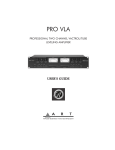
REAR-PANEL CONNECTIONS
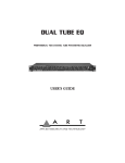
Input 1-8
The Pro Gate’s Inputs are designed to accept balanced or unbalanced signal sources. The 1/4" TRS jack (Tip = hot/Ring = cold/
Sleeve = ground) can be connected to balanced gear with either 1/4" tip/ring/sleeve or XLR connections (using a cable with a TRS
plug on one end and an XLR plug on the other). If you aren’t using the Pro Gate with a balanced source, simply use shielded cords
with standard 1/4" TS plugs, and the connection will be unbalanced. For connections using other plug types, see page 28.
Note: Unbalanced connections are at a level of -10dBV. Balanced connections are at a level of +4dBm. Balanced/unbalanced selection
is global and set via the System Edit menu (see page 22). The System I/O (input/output) setting applies to output level for matching
to system levels.
Inputs 1-4
Inputs 5-8
10
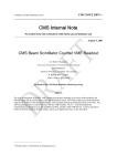
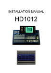
Output 1-8
The Pro Gate’s Outputs are designed to connect with equipment requiring either balanced or unbalanced signal sources. The 1/4"
TRS jack (Tip = hot/Ring = cold/Sleeve = ground) can be connected to balanced gear with either 1/4" tip/ring/sleeve or XLR connections (using a cable with a TRS plug on one end and an XLR plug on the other). If you aren’t running the Pro Gate’s output to
gear with a balanced input, simply use shielded cords with standard 1/4" TS plugs, and the connection will be unbalanced. For connections using other plug types, see page 28.
Note: Unbalanced connections are at a level of -10dBV. Balanced connections are at a level of +4dBm. Balanced/unbalanced selection is global and set via the System Edit menu (see page 22).
Outputs 1-4
Keys 1-4
Outputs 5-8
Keys 5-8
Key 1-8
Each channel has a 1/4" unbalanced key input that accepts a signal for external keying (triggering) of that channel’s gate. The Pro
Gate is factory set so that all eight channels trigger from the signal present at their Input jacks (Internal keying). You can change a
channel’s Key source from internal to external or MIDI by choosing a channel via the Channel Select buttons and pressing the
Source Button to choose Int., Ext., or MIDI (Internal, External, or MIDI) triggering. See Using The Rotary Encoder, page 15, for
another way to change the channels’ keying.
11
Non-Destructive Key Listen Audition
This output monitors the signal present at any of the eight key inputs. This is useful for setting your HPF and LPF frequencies and
checking that a signal is present at a key input. Use the Channel Select button to choose a channel; the signal from that channel’s key
is automatically routed to the Non-Destructive Key Listen Audition output. This includes either the internal or key inputs; when a
MIDI key is used, the Key Listen will receive the signal from the external key
as a default. The Non-Destructive Key Listen Audition output is typically
sent to a separate channel on a mixing console that is monitored by the engineer, but not sent to tape or to a house or stage monitor mix.
Note: The Key Listen output level is set at -10dB.
MIDI In
The jack labeled MIDI In receives the MIDI signal containing MIDI
Program Change messages, Note On/Note Off messages for keying, or MIDI
Continuous Controller messages for real-time control. It enables you to “talk”
to the Pro Gate from an external source such as a computer equipped with
MIDI ports and associated software, or a sequencer.
MIDI Thru
The MIDI Thru jack passes data entering the MIDI In jack to other gear.
The Pro Gate does not contain a MIDI merger.
MIDI Out
The MIDI Out jack is used for sending data such as Note On/Note Off commands for triggering external sources from the Pro Gate
to other MIDI gear. It is also the port used for sending complete data dumps to other MIDI devices for storage.
12
TUTORIAL FOR USING THE PRO GATE
The Pro Gate is designed so that you can operate eight noise gates as easily as a single-channel unit. You can use the four buttons at
the unit’s far left side along with the eight Channel Select buttons and the six knobs below the LCD display window to control all
basic functions. In addition, you can use the large Rotary Encoder to speed you through the functions and settings. The following
tutorial guides you through these operations. The next section, Editing Mode (page 17), takes you through programming functions.
Getting Started
Connect an audio source to any of the Pro Gate’s inputs, and send the outputs to a mixer. (Alternatively, you can place the Pro Gate
in the insert points on a mixer.) Connect the Non-Destructive Key Listen Output to another channel on the mixer. Turn on the Pro
Gate, and bring up the levels on your mixer and monitor system to normal listening levels.
Upon power-up, the following will show in the LCD display window:
LPF
20K
-20
0.63
Chan. 1.
50
22
-82
Channel Select
Use any of the Channel Select buttons (1-8) to select any gate. The selected gate is indicated in the LCD display window in the
upper row at the center of the screen (Chan. 1, Chan. 2, Chan. 3, etc.). At the same time, the red Channel Selected LED above the
switch shows which channel is selected. Pressing Channel Select button 2 changes the display to look like this:
LPF
20K
-20
0.63
Chan. 2.
50
22
-82
As you press any of the eight Channel Select buttons, the corresponding red LED glows, and the Channel number is shown in the
display.
Note: When channels are linked, the display will tell you so, rather than show parameter values. For example, if Channel 5 is linked
to Channel 4, and you press Channel 5’s Channel Select button, this appears in the LCD window:
Chan. 5.
Linked to Channel 4
This lets you know that you can’t edit parameter values for Channel 5, because it is a “slave” to Channel 4, and therefore is controlled
by Channel 4’s settings. For more on Channel linking, see page 16.
The six knobs labeled Key Filter, Threshold, Attack, Hold, Release, and Range are always “live.” That is, when a channel is selected,
any of these parameters can be adjusted. The current settings for each parameter are shown in the lower row of the LCD display window. The Pro Gate automatically stores any changes you make to any knob or switch, and retains changes in memory even if the unit
is turned off or unplugged.
13
Bypass
Any selected channel can be bypassed by pushing the Bypass switch; it remains in Bypass mode until the Bypass switch is pushed
again when that channel is selected. For example, if Chan. 1 is selected and you push Bypass, and then select any other channel,
Chan. 1 will remain in its bypassed mode until you press Channel Select switch 1 again and then press Bypass.
LPF
20K
-20
0.63
Chan. 1.
50
22
Bypass
-82
Note: You can also use the Rotary Encoder and Channel Select switches to check and change all eight channels’ Bypass states. See
Rotary Encoder For Key Source, Link, Bypass, Song Functions, page 15.
If you need to bypass all eight channels simultaneously, you can turn the Pro Gate off. When the power is restored, the last screen is
displayed and the Song in use when the power was turned off is again selected.
Key Listen
The Key Listen button sends the output of the Key to the output of the selected channel (it interrupts the gate audio). The NonDestructive Key Listen Audition jack always has the key output of the selected channel (used for “non-destructive” listening). That is,
you don’t have to press Key Listen to send audio to the Non-Destructive Key Listen Audition output. Pressing the Key Listen button
when any channel is selected sends that channel’s key source (Internal or External) to the output of that channel. You know that a
channel is selected for Key Listen because the corresponding channel’s Channel Select LED blinks, and the word “Listen” appears in
the top row of the LCD window. The LED remains blinking, and the word “Listen” remains in the window, until you push the Key
Listen button again. Choosing any other channel by pressing a Channel Select button also disengages the Key Listen function.
LPF
20K
-20
0.63
Chan. 1.
50
22
Listen
-82
Note: The Key Listen functions normally even if the channel is in Bypass mode.
Source
The factory default of Int. for the Key and values of 25 Hz for the HPF and 20kHz for the LPF are considered as a “bypass.” Pressing
the Source button when any channel is selected lets you choose how the gate for that channel is keyed (triggered). Select a channel,
press Source, and in the top row of the LCD window you’ll see the current keying mode Int., Ext., or MIDI (internal, external, or
MIDI). The factory default is internal keying (Int.); that is, the channel keys off of the audio signal present at that channel’s input.
Pressing the Source button again advances the key source to the next choice, cycling through the choices until you stop pressing the
button (from Int. to Ext., Ext. to MIDI, MIDI to Int., etc.). The selected key source remains showing for 4 seconds, and then it disappears from the display. The selected key source remains in memory for that channel until it is changed. You may check a channel’s
key source by selecting the channel and then pressing Source. The key source will show in the LCD display for 4 seconds.
LPF
20K
Int.
-20
0.63
Chan. 1.
50
22
-82
Note: You can also use the Rotary Encoder and Channel Select switches to check and change all eight channels’ Key Sources. See
Rotary Encoder For Key Source, Link, Bypass, Song Functions, page 15.
14
Freq
Each channel’s internal key has two filters, a low-pass (LPF) and high-pass (HPF), which allow you to tailor the frequency response
range of the key (more on this in the Applications section, starting on page 29). Each time you press the Freq key, you’ll see the left
portion of the LCD window toggle between “LPF” and “HPF.” The current value for each filter is shown below HPF or LPF.
Turning the Key Filter knob below the display adjusts the filter.
LPF
20K
Int.
-20
HPF
25
Int.
-20
0.63
Chan. 1.
50
22
-82
0.63
Chan. 1.
50
22
-82
USING THE ROTARY ENCODER FOR KEY SOURCE, LINK, BYPASS, SONG FUNCTIONS
The Rotary Encoder provides a fast Overview approach to checking and adjusting parameters for all eight channels of the Pro Gate.
Turning the Rotary Encoder clockwise lets you check the following for all eight channels at once:
• Key Source
• Link (channel linking)
• Bypass mode
• Song
Any changes you make are automatically stored and remain in memory until you change them.
Key Source
Turning the Rotary Encoder one “click” to the right shows the Key Source for all eight channels in the LCD display window:
Key Source
Overview
:
1
I
2
I
3
I
4
I
5
I
6
I
7
I
8
I
The top row shows each channel number, and the lower row (Overview) shows I, E, or M to indicate Internal, External, or MIDI keying
on each channel. You can use any of the eight Channel Select buttons to toggle through the three sources for each channel. For example,
if you want to change Channel 4’s key source, press Channel Select button number 4 to cycle through to the desired source.
Key Source
Overview
:
1
I
2
I
3
I
4
I
5
I
6
I
7
I
8
I
Key Source
Overview
:
1
I
2
I
3
I
4
E
5
I
6
I
7
I
8
I
Key Source
Overview
:
1
I
2
I
3
I
4
M
5
I
6
I
7
I
8
I
After you make any change to the key source for any channel, it is automatically saved in memory.
15
Link
Turning the Rotary Encoder one click beyond Key Source activates the Link information:
Link
Overview
:
1
2
3
4
5
6
7
8
*
By linking channels, you can use one channel’s key source to trigger the gate of the adjacent channel(s) to the right. Pressing a
Channel Select button changes the display from unlinked (nothing showing below the channel number in the LCD window) to
linked (indicated by an arrow pointing to the left followed by the letter “L”). Notice that an asterisk (*) is shown for Channel 1; this
reminds you that Channel 1 has no lower channel to link to.
If you press, for example, Channel Select buttons 3 and 6, the following appears in the LCD display:
Link
Overview
:
1
2
*
3
<–L
4
5
6
<–L
7
8
It tells you that Channel 3 is linked to Channel 2, and Channel 6 is linked to Channel 5.
Note: When channels are linked, the lowest-numbered channel acts as a master, and its control settings govern any channels linked to it.
Bypass
Turning the Rotary Encoder one click beyond Link activates Bypass information:
Bypass
Overview
:
1
2
3
4
5
6
7
8
A letter “B” is displayed below the channel number whenever a channel is in its bypass mode. For example, press Channel Select buttons number 3 and 4, and the display confirms that those channels are bypassed like this:
Bypass
Overview
:
1
2
3
B
4
B
5
6
7
8
Pressing the Channel Select button of any bypassed channel takes it out of bypass mode.
Note: There is no “global” bypass mode to bypass all eight channels. If it’s necessary to bypass all eight channels, turn the Pro Gate
off. This opens all eight channels’ relays, allowing all channels to be bypassed simultaneously. When power is restored, the channels
that were bypassed are again bypassed.
16
Song Overview Screen
The last (fourth) click of the Rotary Encoder brings up a display that shows the current Song selection and allows you to save current
settings or recall a new Song.
If the current settings are already stored in memory, brackets will default to Recall New Song. Pressing Select moves you to the Recall
Song Over Current section of the System Edit menu. See page 24 for details.
If the current settings are not stored in memory, brackets will surround Save. The save option will only be displayed if the settings
have changed from the Song settings in memory. Pressing Select moves you to the Select Save Song Number (save location) section of
the System Edit menu. See page 23 for details.
Pressing Menu moves you to the other option, Recall New Song. By choosing Recall New Song, you have made the decision to not
store the current settings.
EDITING MODE (CHANNEL, SYSTEM, MIDI)
When you turn the Pro Gate on, it returns to the last screen displayed before you turned it off. If you are turning it on for the first
time, the screen you will see is:
LPF
20K
-20
0.63
Chan. 1.
50
22
-82
To enter Channel, System, and MIDI programming mode, press the Menu button. You will now see this:
Chan. 1.:
Channel System MIDI [Back]
Working in this mode, the Menu and Select buttons are used to make your choices.
Menu
This button moves you to the next available option (or menu) on a screen.
Select
This button selects an item or confirms an action. When the brackets highlight the menu that you wish to choose or action
you would like to perform, press Select to execute the command.
17
Each time you press the Menu button, the brackets surround the next option (Channel, System, MIDI, Back, Channel, System,
MIDI, etc.) in succession. You can edit/program the functions in each of these groups by pressing the Select button and following the
menu instructions at each level. The operations for each of these are outlined in the next three sections. Here is a quick index to these
functions:
Channel
Editing
System
Editing
MIDI
Editing
Operations . . . . . . . . . . . . . . . . . . . . . . . . . . . . . . . . . . . . . . . . . . . . . . . . . . . . . . . . . . Page 19
Edit Channel Name
Link To Channel
Copy Settings To Another Channel
Edit MIDI Parameters For That Channel
MIDI Channel
MIDI Key Note Value
MIDI Trigger Note Value
MIDI Attack Time Continuous Controller
MIDI Release Time Continuous Controller
MIDI Threshold Continuous Controller
Operations . . . . . . . . . . . . . . . . . . . . . . . . . . . . . . . . . . . . . . . . . . . . . . . . . . . . . . . . . . Page 22
Unlink All Channels
Save Settings As A Song
Select Save Song Number
Edit A Song’s Name
Overwrite A Song
Recall A Song Over The Current Song
Set System Input/Output Connections For Balanced Or Unbalanced Operation
Set LCD Viewing Angle
Lock/Unlock Channel Controls
Operations . . . . . . . . . . . . . . . . . . . . . . . . . . . . . . . . . . . . . . . . . . . . . . . . . . . . . . . . . . Page 25
Edit System MIDI Channel
Set MIDI Mode (Omni On/Off )
Edit MIDI Program Table (MPT)
Dump Current Song
Dump All Songs
Dump MIDI Program Table
Next And Back
The Menu and Select buttons provide a way to move quickly forwards and backwards through the screens. Use the Menu button to
move the brackets to either Next or Back, and each time you press Select, the screen will change to either the next one or the previous
one. In addition, if the selection is Next, then each time you press Select, it will keep going to the next screen each time you press the
Select button; the word Next will automatically be bracketed on each screen. Similarly, if Back is selected, then each time you press
Select, you will go to an earlier screen each time you press Select.
18
CHANNEL EDIT FUNCTIONS
Each Channel offers the following functions for editing:
•
•
•
•
Channel Name
Link To Channel
Copy Settings To Another Channel
Edit MIDI Parameters For That Channel
MIDI Channel
MIDI Key Note Value
MIDI Trigger Note Value
MIDI Attack Time Continuous Controller
MIDI Release Time Continuous Controller
MIDI Threshold Continuous Controller
Note: Once you have made a change to any Channel parameter, your new setting remains in memory until you change it again. You
can go back to the previous screen or function by pressing Menu until the word Back is shown in brackets and then pressing Select.
You can exit to the main display at any time by pressing any front-panel button, or by turning any knob (except the Rotary Encoder)
one click in either direction.
Note: all settings shown in this section are for Channel 1 (except for Channel Linking). The procedures are the same for channels 2
through 8.
To Enter Channel Edit mode, press Menu until Channel is shown in brackets. Then press Select.
Edit Chan. 1.: Channel name:
"Chan. 1."
[Next] Back
To change name: Press Menu twice until the Channel name is in brackets. The first character will be underlined. Turning the Rotary
Encoder selects other characters including letters, numerals, and symbols. Once you have changed a character, press Select to advance
to the next one. If you want to revise a character that you already revised, press Select as many times as necessary until the underline
is beneath that character again (pressing Select advances through all eight characters and then cycles back to the first character).
Continue this process until you have finished naming the channel.
Note: The name will remain in memory until you change it, or until you change Songs, unless you save the current Song. For details
on saving a Song, see “System Edit: Save settings as a song?,” on page 23.
If you wish to continue to the next level, press Menu once so that the word Next is shown in brackets.
To go to the Next level, press Select:
Edit Chan. 2.: Link to channel 1?
Yes
[Next]
Back
Note that this example is for Channel 2; Channel 1 can’t link to lower-numbered channels, because there are none. You can link the
Channel (in this case, Channel 2) to the next lower-numbered channel by pressing Menu twice, so the brackets surround Yes. You
can also select Next, and proceed to the next operation, Copy Settings To, or you can choose Back to go back to the previous screen.
19
When you press Select, the link is made, and you see this:
Edit Chan. 2.: Linked to channel 1.
Remove Link
[Next]
Back
If you choose to remove the link, you can press Select twice to surround Remove Link with the brackets, and then press Select to
remove the link.
To go to the Next level, press Select:
Edit Chan. 1.: Copy settings to:
Channel 2
[Next] Back
This lets you copy settings from one Channel to another. This lets you set up identical parameters for multiple channels, which you
can use as-is, or modify to suit your needs.
To change settings: Press Menu twice until the Channel number is in brackets (if the next highest Channel has not been modified,
the number of that Channel will be shown). Turning the Rotary Encoder selects other Channel numbers.
If you wish to continue to the next level, press Menu once so that the word Next is shown in brackets.
To go to the Next level, press Select:
Edit Chan. 1.: Edit MIDI parameters?
[Yes] Back
To edit MIDI parameters: Press Select:
Edit Chan. 1.: MIDI Channel
Channel=Off
[Next] Back
To change MIDI channel settings: Press Menu twice until the Channel=Off is in brackets. Turning the Rotary Encoder selects MIDI
channels 1 through 16 (or Off). This is the MIDI channel that the selected channel of the Pro Gate responds to in MIDI applications.
Once you have selected a MIDI channel, if you wish to continue to the next level, press Menu once so that the word Next is shown
in brackets.
To go to the Next level, press Select:
Edit Chan. 1.: MIDI key note value.
Note= Off
[Next] Back
The MIDI Key Note Value sets which MIDI note the Key will respond to if an external MIDI device sends a Note On/Note Off
message to the Pro Gate.
20
To select MIDI key note value: Press Menu twice until the Note= Off is in brackets. Turning the Rotary Encoder selects a MIDI key
note (Off, or 1 through 127; the corresponding letter/numeral note value is also shown). This sets which note value this Channel will
respond to, if a MIDI command is sent to the Pro Gate.
Note: For a chart showing all MIDI Note values, see page 43.
Once you have selected a MIDI key note value, you can continue to the next level by pressing Menu once, so that the word Next is
shown in brackets.
To go to the Next level, press Select:
Edit Chan. 1.: MIDI trigger note value.
Note= Off
[Next] Back
The MIDI trigger note value is the MIDI Note number that the Pro Gate sends out to other gear to trigger external sound modules,
etc. Each time a Channel’s gate opens, a MIDI Note On/Note Off command is sent out.
To select MIDI Trigger Note value: Press Menu twice until the Note= Off is in brackets. Turning the Rotary Encoder selects a MIDI
key note (Off, or 1 through 127; the corresponding letter/numeral note value is also shown). This sets which note value this Channel
will send when the gate opens.
Note: For a chart showing all MIDI Note values, see page 43.
Once you have selected a MIDI key note value, you can continue to the next level by pressing Menu once so that the word Next is
shown in brackets.
To go to the Next level, press Select:
Edit Chan. 1.: MIDI attack time.
Controller= – – – – – – – – – (Off)
[Next] Back
MIDI Continuous Controller data can be used to adjust a Pro Gate Channel’s attack time. You can set the MIDI Continuous
Controller value that this Channel responds to, or you can set it to Off, so it doesn’t respond to MIDI data. (Off is the default value.)
To change settings: Press Menu twice until the Controller= (Off ) is in brackets. Turning the Rotary Encoder selects a MIDI Continuous Controller value (Off, or 1 through 119; see page 40 for a complete MIDI chart). This sets the MIDI Continuous Controller
that this Channel will respond to, for changing this Channel’s Attack Time from a sequencer or other MIDI device.
Once you have selected a MIDI Continuous Controller value, you can continue to the next level by pressing Menu once so that the
word Next is shown in brackets.
21
To go to the Next level, press Select:
Edit Chan. 1.: MIDI release time.
Controller= – – – – – – – – – (Off)
[Next] Back
MIDI Continuous Controller data can be used to adjust a Pro Gate Channel’s release time. You can set the MIDI Continuous Controller value that this Channel responds to, or you can set it to Off, so it doesn’t respond to MIDI data. (Off is the default value.)
To change settings: Press Menu twice until the Controller= (Off ) is in brackets. Turning the Rotary Encoder selects a MIDI
Continuous Controller value (Off, or 1 through 119; see page 40 for a complete MIDI chart). This sets the MIDI Continuous
Controller that this Channel will respond to, for changing this Channel’s Release Time from a sequencer or other MIDI device.
Once you have selected a MIDI Continuous Controller value, you can continue to the next level by pressing Menu once so that the
word Next is shown in brackets.
To go to the Next level, press Select:
Edit Chan. 1.: MIDI threshold.
Controller= – – – – – – – – – (Off)
[Back]
MIDI Continuous Control data can be used to adjust a Pro Gate Channel’s threshold. You can set the MIDI Continuous Controller
value that this Channel responds to, or you can set it to Off, so it doesn’t respond to MIDI data. (Off is the default value.)
To change settings: Press Menu twice until the Controller= (Off ) is in brackets. Turning the Rotary Encoder selects a MIDI Continuous Controller value (Off, or 1 through 119; see page 40 for a complete MIDI chart). This sets the MIDI Continuous Controller
that this Channel will respond to, for changing this Channel’s Threshold level from a sequencer or other MIDI device.
Note: There is no next level, so you must either choose to go Back using the Select button, or return to the main menu display by
pushing any panel button or turning any knob (except the Rotary Encoder) by one click.
SYSTEM EDITING FUNCTIONS
The menus for System editing are:
•
•
•
•
•
•
Unlink All Channels
Save Settings As A Song
Select Save Song Number
Edit A Song’s Name
Overwrite A Song
Recall A Song Over The Current Song
Set System Input/Output Connections For Balanced Or Unbalanced Operation
Set LCD Viewing Angle
Lock/Unlock Channel Controls
To enter System Edit mode, press Menu until System is shown in brackets. Then press Select.
22
Once you have made a change to any System parameter, your new setting remains in memory until you change it again. You can go
back to the previous level by pressing Menu until the word Back is shown in brackets and then pressing Select. You can exit to the
main display at any time by pressing any front-panel button, or by turning any knob (except the Rotary Encoder) one click in either
direction.
Note: All parameters affected by System Editing are global. That is, they affect the current Song or System setting.
You will see one of these two messages:
System Edit: Channels are unlinked.
[Next] Back
or
System Edit: Unlink all channels?
Yes
[Next] Back
The first message is the default value for the Pro Gate, and one that will appear if you have not linked any channels (for information
on linking channels, see page 16). It informs you that no channels are linked, and requires no action on your part. You may either
proceed to the next level or go back to the main System menu.
The second message appears if any channels have been linked. You have the option of unlinking all channels by pressing Menu twice
so that Yes appears in brackets. Then press Select to unlink all the channels. When you unlink the channels, this message appears:
System Edit: Channels are unlinked.
[Next] Back
To go to the Next level, press Select:
System Edit: Save settings as a song?
Yes
[Next] Back
To save settings as a Song: Press Menu twice until Yes is in brackets. Press Select to save the settings for all eight channels as a Song.
(If you don’t want to save changes, press Select to enter the next level; see Recall Over Current, page 24.)
System Edit: Select save song number.
Song #= 1
[Next] Back
The Pro Gate will automatically call up the next available Song location. There are 20 internal locations. Once all available internal
locations are occupied, the Pro Gate will ask if it is okay to overwrite an existing location.
To change Song number: Press Menu twice until Song # is in brackets. Turn the Rotary Encoder to select a Song number (1 through
20). Press Select to save the Song number. Note that when you turn the Rotary Encoder, the name of each Song will also appear in
the LCD window, next to the Song number. Once you have made your selection, press Menu once so that Next is in brackets.
To go to the Next level, press Select:
System Edit: Song name:
"Song (A)"
[Next] Back
23
To go to the Next level, press Select:
System Edit: Song name:
"Song (A)"
[Next] Back
To change Song name: Press Menu twice until a song title such as "Song (A)", "Song (B)", "Song (C)", etc., is in brackets. Note that
"Song (A)", "Song (B)", "Song (C)", etc., is the default name for an unnamed song. The first character of the Song name will be
underlined. Turning the Rotary Encoder selects other characters including letters, numerals, and symbols. Once you have changed a
character, press Select to advance to the next one. If you want to revise a character that you already revised, press Select as many times
as necessary until the underline is beneath that character again (pressing Select advances through all eight characters and then cycles
back to the first character). Continue this process until you have finished renaming the Song. Once you have completed naming the
Song, press Menu once so that Next is in brackets.
To go to the Next level, press Select:
System Edit: Overwrite song "Song (A)"?
[Yes] Back
Note: This is a confirmation screen. If you incorrectly choose a location, choose Back to cancel the Save command, and choose
another location.
To save to the selected location: Press Select to overwrite the Song. You will see this message, confirming that your Song has overwritten the old Song and has been saved.
System Edit: Song saved.
[Next] Back
If you press the Select button, you will be asked whether you want to recall a Song. The window displays this message:
System Edit: Recall song over current.
Song #= 1
[Next] Back
Pressing the Menu button twice gives you this screen:
System Edit: Recall song over current.
[Song #= 1]
"Song (A)"
[Next] Back
Turning the Encoder clockwise increases the number of the Song ("Song #= 1", "Song #= 2", "Song #= 3", etc.), and the corresponding Song name changes as well. Once you have decided which Song you would like to recall, press the Select button. The Song will
be recalled and you will be returned to the main screen.
Selecting Next with the Menu button accesses the System input/output (I/O) connections’ settings:
System Edit: System I/O connections:
Balanced
[Next] Back
The default value is Balanced. This setting is optimal for use in the insert channels on professional-level mixing consoles. If you plan
to plug an instrument directly into the Pro Gate, set this for Unbalanced (press the Menu button until the word Balanced is shown in
brackets. Then turn the Rotary Encoder until [Unbalanced] is shown.
24
Press the Menu button to select Next. Then press Select. You will see this screen:
System Edit: LCD viewing Angle:
View=1 [Next] Back
Pressing Menu twice gives you this screen:
System Edit: LCD viewing Angle:
[View=1]
Next Back
Turn the Rotary Encoder to adjust the viewing angle (the values change from 1 to 9). Once you have set the viewing angle to your
taste, press Menu to advance to Next.
Pressing Select gives you this window:
System Edit: Lock channel controls?
Yes
[Back]
Pressing Menu changes your choice to Yes. To lock the channel controls, press Select.
The display now shows this message:
System Edit: Unlock channel controls?
Yes
[Back]
Locking the channel controls literally locks their settings in place. That way, if someone fiddles with the dials and switches while
you’re away from the Pro Gate, they can’t alter your settings. The only controls that are “live” are the Channel Select switches, the
Menu button, and the Select button. If you lock the channels using this feature, you must unlock them before you can alter any settings. To do this from the main window, press Menu three times to select [System], and then press Select six times until you see this
display:
System Edit: Unlock channel controls?
Yes
[Back]
There is no next level, so you must either choose to go Back using the Select button, or return to the main menu display by pushing
any panel button or turning any knob (except the Rotary Encoder) by one click.
MIDI EDITING FUNCTIONS
The following are the Global MIDI functions that you can edit via the MIDI screen:
•
•
•
•
•
•
Edit System MIDI Channel
Set MIDI Mode
Edit MIDI Program Table (MPT)
Dump Current Song
Dump All Songs
Dump MIDI Program Table
25
Note: Once you have made a change to any MIDI parameter, your new setting remains in memory until you change it again. You
can go back to the previous level by pressing Menu until the word Back is shown in brackets and then pressing Select. You can exit to
the main display at any time by pressing any front-panel button, or by turning any knob (except the Rotary Encoder) one click in
either direction.
To Enter MIDI Edit mode, press Menu until MIDI is shown in brackets. Then press Select.
MIDI Edit: System MIDI channel.
Channel = 1
[Next] Back
Editing the System MIDI channel allows you to set the MIDI channel over which the Pro Gate will receive Program Change and
send other commands. The default value is Channel 1.
To set system MIDI channel: Press Menu and then turn the Rotary Encoder to select MIDI Channel 1 through 16 (Channel 1 is the
default setting). This sets the MIDI channel on which the Pro Gate receives and sends data.
If you wish to continue, press Menu once so that the word Next is shown in brackets.
To go to the Next level, press Select:
MIDI Edit: Omni mode.
Omni = Off
[Next] Back
Omni Mode (also known as Omni On/Poly, or Mode 1) allows the Pro Gate to respond to data over any of MIDI’s 16 channels. The
default value is Off, which means that the Pro Gate is set so that it will only send and receive on the system MIDI channel.
To change Omni Mode: Press Menu twice (so that Omni = Off is in brackets) and then turn the Rotary Encoder to change it to Omni = On.
If you wish to continue, press Menu once so that the word Next is shown in brackets.
To go to the Next level, press Select:
MIDI Edit: MIDI Program Table (MPT)
Program= 1
Song #= 1
[Next] Back
The MIDI Program Table is a means of setting up the Pro Gate to recall specific Song numbers when specific Program Change commands come in.
To change MIDI Program Table: Press Menu until brackets surround Program. Then turn the Rotary Encoder to make your Program
selection. Program numbers can range from 1 to 128, while Songs range from 1 through 20. Default values are set so that Program 1
= Song #1, Program 2 = Song #2, etc., up to Song #20; then Song numbers repeat at Song #1, Song #2, etc. Once you have selected
the Program number, press Menu (the brackets will surround the Song number). Turn the Rotary Encoder to choose the Song number that you want to correspond with the Program number.
26
To change another Program/Song combination, press Menu three times (until Program is surrounded by brackets), and repeat the
previous procedure.
If you wish to continue, press Menu until the word Next is shown in brackets.
To go to the Next level, press Select:
MIDI Edit: Dump current song.
Perform [Next] Back
To dump the MIDI data for the current Song to external MIDI storage devices or sequencers, press the Menu button twice until the
word Perform is shown in brackets. When your other MIDI gear is ready to receive the data transfer, press Select. Make sure that
your MIDI cable is connected from the Pro Gate MIDI Out jack (not MIDI Thru) to the MIDI In jack of your receiving MIDI
gear. You should then see this message, which tells you the data was transferred:
MIDI Edit: Transfer completed.
[Next] Back
To go to the Next level, press Select:
MIDI Edit: Dump all songs.
Perform [Next] Back
To dump all Songs to external MIDI storage devices or sequencers, press the Menu button twice until the word Perform is shown in
brackets. When your other MIDI gear is ready to receive the data transfer, press Select. Make sure that your MIDI cable is connected
from the Pro Gate MIDI Out jack (not MIDI Thru) to the MIDI In jack of your receiving MIDI gear. You should then see this message, which tells you the data was transferred:
MIDI Edit: Transfer completed.
[Next] Back
To go to the Next level, press Select:
MIDI Edit: Dump MIDI Program Table.
Perform [Back]
To dump the MIDI Program Table (MPT) to external MIDI storage devices or sequencers, press the Menu button twice until the
word Perform is shown in brackets. When your other MIDI gear is ready to receive the data transfer, press Select. Make sure that
your MIDI cable is connected from the Pro Gate MIDI Out jack (not MIDI Thru) to the MIDI In jack of your receiving MIDI
gear. You should then see this message, which tells you the data was transferred:
MIDI Edit: Transfer completed.
[Back]
Note: There is no next level, so you must either choose to go Back using the Select button, or return to the main menu display by
pushing any panel button or turning any knob (except the Rotary Encoder) by one click.
27
CABLES & CONNECTORS
The Pro Gate’s audio inputs and outputs are designed to accept 1/4" plugs. For balanced operation, a TRS (tip/ring/sleeve) plug is
appropriate, and for unbalanced operation, a standard mono or TS (tip/sleeve) plug is necessary. Since other gear uses a variety of
input and output jacks, we’ve included the following chart for proper interfacing between the Pro Gate and other equipment. (Note:
Because 1/4" TS to 1/4" TS and 1/4" TRS to 1/4" TRS configurations follow the logical tip-to-tip, ring-to-ring, sleeve-to-sleeve format, they are not included in the diagrams. Also note that the External key inputs are all unbalanced, as is the Non-Destructive Key
Listen Audition output.)
Pro Gate
Output
Connections
1/4" T/R/S Plug
T
R
S
= T
= S
= S
Other Gear
1/4" T/S Plug
Unbalanced Input
Balanced Input
Output
1/4" T/R/S Plug
T
R
S
= Pin 2
= Pin 3
= Pin 1
XLR Male Connector
Balanced Input
Output
1/4" T/S Plug
Output
1/4" T/R/S Plug
Output
1/4" T/S Plug
T
S
= Pin 2
= Pin 3
Shield
To
Pin 1
T
= T
R (NC)
S
= S
T
S
= T
= S
XLR Male Connector
Phono (RCA)
Plug
Unbalanced
Phono (RCA) Input
Phono (RCA)
Plug
Unbalanced
Phono (RCA) Input
Balanced Output
Input
1/4" T/R/S Plug
T
R
S
= Pin 2
= Pin 3
= Pin 1
XLR Female Connector
Balanced Output
Input
28
1/4" T/S Plug
T
S
= Pin 2
= Pin 3
Shield
To
Pin 1
XLR Female Connector
PRO GATE APPLICATIONS & SETUP DIAGRAMS
Many people associate gates with a snap-open/snap-shut type of application. However, the ART Pro Gate’s wide range of controls
allow you to control signals in a multitude of creative ways. If you’ve worked with noise gates before, you can apply what you
know—to one, two, or as many as eight gates at once.
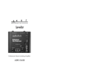
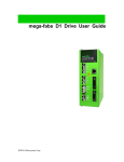
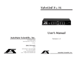
Using The Pro Gate With A Mixer, A Multi-Track Recorder, And A Mix-Down Recorder
Patch the Pro Gate into the insert points of a mixing console and set the Pro Gate’s keying to Internal. Connect the mix-down
recorder (DAT, reel-to-reel, cassette) to the mixer’s outputs. Note: In the diagram below, connections for only four channels of the
Pro Gate are shown. Add more channels as necessary.
Pro Gate
GATE CLOSED
CHANNEL SELECTED
Hz
dB
Milliseconds
Milliseconds
Milliseconds
4
dB
3
2
Mixer
Insert
Points
1
Multi-track
Recorder
DAT
Recorder
Mixing
Console
S
E
N
D
R
E
T
U
R
N
S
E
N
D
R
E
T
U
R
N
S
E
N
D
R
E
T
U
R
N
S
E
N
D
R
E
T
U
R
N
Rear Of
Pro Gate
Note: Patching is shown only for four channels. Connect
the other four channels in the same manner.
29
Simple Gating To Control Noise & Isolate Instruments
Sometimes a sound source is plagued by hiss or low-frequency rumble, but is otherwise good. An example of this is electric guitar
through an amp, where the amp is running at such high gain that the hiss is very noticeable whenever the guitarist isn’t playing.
Setting the gate’s threshold to open only when the sound exceeds the hiss level lets you chop out the noise. Be careful to set a fast
attack time and a moderately slow release time so that notes and harmonics (such as from decaying chords) don’t get chopped off.
This noise-reduction technique can be useful when recording samples, too.
When multiple microphones are used onstage, you can set the Range controls on each gated mic so that rather than completely shutting a channel off when the intended source isn’t present (a vocalist or horn player, for example), the mic doesn’t go “dead,” which
can make the entire mix sound skewed. The Range control allows you to set the amount of attenuation when the gate is off.
Drumset
With
Multiple
Microphones
GATE CLOSED
Pro Gate
Mixing console
30
CHANNEL SELECTED
Hz
dB
Milliseconds
Milliseconds
Milliseconds
dB
4
S
E
N
D
3
R
E
T
U
R
N
2
S
E
N
D
R
E
T
U
R
N
Mixer
Insert
Points
1
S
E
N
D
R
E
T
U
R
N
S
E
N
D
R
E
T
U
R
N
Rear Of
Pro Gate
Note: Patching is shown only for four channels. Connect
the other four channels in the same manner.
31
Keying From A Second Source
A tight rhythm section is a wonderful thing to hear. Try as you might, though, you can’t always get the kick drum and the bass guitar
notes exactly locked in sync. Using the kick drum to key a gated bass guitar can work wonders here. By setting the attack and release
times very short on the bass’ channel and keying it with the kick drum, the gate only opens when the kick drum is present. Note:
This technique should only be used when the instruments must be firmly locked. You can loosen up the feel by lengthening the
Release time.
A variation is to use the kick drum to key the sound of a continuous low-frequency tone such as that produced by a low-frequency
oscillator. This can create an extra-big bass drum sound. Set a short attack time and adjust the “tightness” of the composite sound by
experimenting with Hold and Release settings.
Sound Source
(Bass Guitar)
Key Source
(Bass Drum)
GATE CLOSED
Pro Gate
CHANNEL SELECTED
Hz
dB
Milliseconds
Milliseconds
Milliseconds
dB
Mixing
Console
32
Mixer’s
Insert
Point
(Bass
Guitar)
Key
Source
(Bass
Drum)
Insert
S
E
N
D
Rear Of
Pro Gate
R
E
T
U
R
N
Out
K
E
Y
I
N
Audio
Signal
Source
(Oscillator)
Mixer Or
Amplifier
Out In
S
E
N
D
R
E
T
U
R
N
Key
Source
(Bass
Drum)
Out
K
E
Y
I
N
Rear Of
Pro Gate
33
Using The Non-Destructive Key Listen Audition
The Non-Destructive Key Listen Audition provides a non-destructive output for monitoring the Pro Gate’s Key filters. Connect the
Pro Gate’s Non-Destructive Key Listen Audition output to the input of a free mixer channel that is not going to the house, recording, or onstage monitor mixes. The Key audio output of the currently selected channel is automatically routed to this output.
In addition to showing patching for the Non-Destructive Key Listen Audition, it shows three methods of connecting signals for signal processing and keying. From left to right, they are: In the insert point of a mixer channel (internal keying), in the insert point of a
mixer channel (with external keying from another source), and in the signal path from one piece of audio gear (such as a synthesizer)
to another (such as a mixer’s input), with a separate external key source.
Mixer Source
Insert For
Point Key
Mixer
Insert
Point
Insert
S
E
N
D
Rear Of
Pro Gate
34
R
E
T
U
R
N
Insert Out
S
E
N
D
R
E
T
U
R
N
K
E
Y
I
N
Signal
Output
From
One
Piece
Of
Audio
Gear
Out
Output
To
Second
Piece
Of
Audio
Gear
In
Non-Destructive
Key Listen
Audition
To Channel
On Mixing
Console
In
NonDestructive
Key Listen
Audition
Reshaping Samples
Gating out noise while setting a high enough Threshold so that only strong signals reach a sampler is an effective way to get your best
samples. Set the gate to close when the level is just above the “noise floor”; this makes it easier to find the end point and to set a loop
point. Adjusting the Release time can be helpful in smoothing out the sound of the sample’s decay.
Sound To Be
Sampled
Threshold
Noise
Gate
Envelope
Attack
Hold
Rel
eas
e
Reshaped
Sample
35
Chopping Sounds
Here’s a variation on Keying From A Second Source. Plug a drum machine or other rhythmic source into the Key of a Channel
where the sound being gated isn’t very rhythmic, thereby imparting the sound with the same rhythmic structure as the gating signal.
For example, a strummed guitar or chordal “pad” played on a keyboard makes a good sound source to be shaped by rhythmic keying.
Set Attack, Hold, and Release times short for maximum staccato effect. You can use this technique to replace drum sounds by using
the actual drum sounds to key the gates, and have the new sounds (samples, for example) gated in the proper rhythm.
Sound Source
(Guitar)
Key Source
(Drum Machine)
GATE CLOSED
Pro Gate
Sound Source
Rhythmic
Key
Gated Output
36
CHANNEL SELECTED
Hz
dB
Milliseconds
Milliseconds
Milliseconds
dB
Frequency-Selective Gating
You can adjust the filters on a gate’s internal Key to respond only when certain frequencies are present. It’s possible to set the filters so
that they act as high-pass, low-pass, or bandpass filters. High-pass values to 25 Hz allow all frequencies to pass through, while setting
the Low-pass filter value to 20kHz allows all frequencies to pass through. Setting lower LPF values without changing the HPF values
removes frequencies above those values from the signal entering the Key. Setting higher HPF values without changing LPF values
eliminates low frequencies from the signal reaching the Key. Adjusting both the HPF and LPF values sets a pass band of frequencies
that reach the Key, while excluding frequencies above and below that pass band. Using the HPF can help to keep extraneous low frequencies (such as rumble) from creating false triggering, while lowering the HPF value keeps highs (such as feedback squeal) from
kicking the gate open. Closely adjusting the two filters’ frequencies to just above and below a sound source’s frequency range helps to
minimize false triggering from other sounds, especially important in live, open-mic settings.
Gating Reverb
Reverberated
Signal
Loudness
It’s easy to make reverb appear to swell by altering its “envelope.” Split the signal going into a reverb unit, sending it to both the
reverb’s input and the Key input of one Pro Gate channel. Then connect the reverb’s output to the channel’s Input. Set the Attack to
a long value and the Release to a very short one to get a "reverse reverb" effect. Other effects include using short Attack times and
longer Decay times and setting the key’s HPF value so that low-frequency sounds don’t trigger the gate, but higher ones do. In addition, you can place a digital delay before the channel’s Key input for a delay/splash effect.
Time
Gated
Reverb
Output
Loudness
Key Trigger
Time
Long Attack
Short Release
37
Keying Non-Adjacent Channels From A Single Source
It’s easy to key adjacent channels using the Link feature. However, you can key non-adjacent channels by splitting the first channel’s
output and sending it to the Key point of another channel.
Insert Loop
Of Sound
Source 1
Insert Loop
Of Sound
Source 2
Out In
Out In
Splitter
S
E
N
D
Rear Of
Pro Gate
38
R
E
T
U
R
N
S
E
N
D
R
E
T
U
R
N
K
E
Y
I
N
Output from the
first sound source
keys the second
source’s gate
Using MIDI To Control Gates & Dump Data
A sequencer or MIDI-equipped computer can trigger gates and change their Threshold, Attack, and Release values in real time, making it possible to automate gating procedures. You can use the Pro Gate’s MIDI Thru to send the incoming MIDI data to a second
Pro Gate or other MIDI device. In addition, the Pro Gate’s MIDI Out can be connected to a sequencer or other MIDI device to
store Songs from the Pro Gate. The Pro Gate sends Note On/Note Off commands, as well, which can be used to trigger MIDI
events, replace drums, etc.
Rear Of
Pro Gate
MIDI
IN
Sequencer,
Sampler, Etc.
MIDI
OUT
MIDI
IN
Sequencer Or
Computer
Second
Pro Gate Or
Other
MIDI Gear
39
USING MIDI WITH THE PRO GATE
The Pro Gate is designed so that channels can be keyed via MIDI, and data for Songs can be sent to and from the Pro Gate via
MIDI. In addition, the Pro Gate accepts MIDI Continuous Controller data to make changes in many parameters in real time from
sequencers, MIDI-equipped computers, etc. It can transmit MIDI Note On and Note Off commands from each channel to trigger
other MIDI Gear.
When the Pro Gate is connected to a MIDI network, it processes command messages that tell it what to do. If these messages come
at the Pro Gate at a very fast rate, the Pro Gate may not be able to keep up. If this should occur, the display will show MIDI Error in
the LCD Window. The message will be in the area where normally shows Bypass and Listen. To clear this message, press any Channel
button twice.
You might receive this message if you had all eight Channels configured with a MIDI key source, and you were sending Note
On/Note Off messages at an extremely fast rate (such as a Note On/Note Off pair every 2.5 milliseconds).
If you are not using MIDI or are not using MIDI extensively and still receive a MIDI Error message, there may be a problem with
your Pro Gate. Contact your dealer or ART Customer Service to resolve the problem.
MIDI Controllers & Numbers
Here’s a list of MIDI Controllers and their numbers, which will help you avoid conflicts if you control the Pro Gate and other MIDI
gear in the same setup. The Pro Gate displays controller numbers in decimal form; it does not display them in hexadecimal, although
the hexadecimal equivalent information may be necessary for other gear.
Decimal
0
1
2
3
4
5
6
7
8
9
10
11
12-15
16-19
20-31
32
33-63
64
65
Hexadecimal
00
01
02
03
04
05
06
07
08
09
0A
0B
0C-0F
10-13
14-1F
20
21-3F
40
41
40
Controller Description
Reserved for Bank Select
Mod Wheel
Breath Controller
Undefined
Foot Controller
Portamento Time
Data Entry (MSB)
Main Volume
Balance
Undefined
Pan
Expression Controller
Undefined
General Purpose Numbers 1-4
Undefined
Reserved for Bank Select
LSB For Values 0-31
Damper Pedal (Sustain)
Portamento
Decimal
66
67
68
69
70-79
80-83
84-90
91
92
93
94
95
96
97
98
99
100
101
102-120
Hexadecimal
42
43
44
45
46-4F
50-53
54-5A
5B
5C
5D
5E
5F
60
61
62
63
64
65
66-78
Controller Description
Sostenuto
Soft Pedal
Undefined
Hold 2
Undefined
General Purpose Numbers 5-8
Undefined
External Effects Depth
Tremolo Depth
Chorus Depth
Celeste (Detune) Depth
Phaser Depth
Data Increment
Data Decrement
Non-Registered Parameter Number LSB
Non-Registered Parameter Number MSB
Registered Parameter Number LSB
Registered Parameter Number MSB
Undefined
The MIDI Program Table (MPT)
The MPT’s primary job is to map incoming MIDI Program Change messages to Song numbers. Why would you want to do this?
For example, you might want to make the Pro Gate change to a specific preset when you recall a specific patch on a synthesizer. Most
synthesizers send out a MIDI Program Change message indicating which patch has been recalled. You can then use the MPT to map
that patch number to a desired Song number in the Pro Gate.
By default, the MPT has a one-to-one mapping. That is, when the Pro Gate receives a Program Change message of 0 (zero), it recalls
Song 1. A Program Change message of 1 recalls Song 2, and so on, repeating Song 1 after Song 20, in order up to Program Change
number 127.
Loading Data From A Remote Source
If you have saved the contents from your Pro Gate in another MIDI device, you can load the data into your Pro Gate or another Pro
Gate by connecting a MIDI cable between the other device’s MIDI Out and the Pro Gate’s MIDI In, and then performing a MIDI
Dump from the other device. The Pro Gate will accept the data at any time; you don’t need to set any parameters or values on the
Pro Gate for it to accept the data transfer. However, you must have the Pro Gate set to the same MIDI channel as the sending device.
MIDI IMPLEMENTATION IN THE PRO GATE
Channel Voice Messages
The Pro Gate ignores all Channel Voice messages via MIDI, except Control Change and Program Change messages. These messages
are only acted upon when the Pro Gate’s MIDI channel matches the incoming Channel Voice message or the Pro Gate is set to Omni
On mode.
Program Change
Presets can be changed via MIDI with a Program Change message. The default is a one-to-one mapping of Program Change request
number to Song number, but this may be changed by the user.
Channel Mode Messages
The Pro Gate responds to the Omni On and Omni Off Channel Mode messages. These must match the Pro Gate’s MIDI channel to
be recognized.
System Exclusive (SysEx) Messages
The following chart shows the SysEx messages in the Pro Gate:
Byte
Value (in hex)
Description
1
10
Start of SysEx message
2
1a
ART manufacturer’s ID
3
0x
MIDI channel
4
1C
Pro Gate product ID
5
??
Function ID
...
??
Data
(last)
F7
End of SysEx message
41
The function ID is taken from one of the following:
Unit Handshake
Inbound
Outbound
41
01
This function ID may be used to see if a Pro Gate is present on a channel of a MIDI network. There are no data bytes associated
with this message.
Current Parameters
Inbound
Inbound
Outbound
45 (request)
05
05
This message uploads or downloads the current Song to the unit. When received by the Pro Gate, the unit sets all the channels to the
parameters in the message.
Unit Status
Inbound
Outbound
4d
0d
The inbound message has no data bytes. The outbound message has two data bytes. The first tyte is a bitmap. Bit zero indicates if the
system is locked. Bit one indicates if there has been a MIDI data overrun. The second byte is the software version number of the software, in binary-coded decimal.
Stored Parameters
Inbound
Inbound
Outbound
4B (request)
0B
0B
This message uploads or downloads the 20 Songs stored in the Pro Gate. When received by the Pro Gate, the unit simply stores the
new Song data, but does not affect the current Song.
MPT Parameters
Inbound
Inbound
Outbound
48 (request)
08
08
This message uploads or downloads the MIDI Program Table. When received by the Pro Gate, the unit loads the new MPT, but does
not affect the current song.
Other MIDI Notes
•
•
•
The Pro Gate ignores inbound Active Sensing messages.
The Pro Gate does not generate Active Sensing messages.
The System Reset message is ignored.
For MIDI System Exclusive (SysEx) information, please contact ART’s Customer Service Department.
42
MIDI NOTE CHART
The following chart shows the relationship of MIDI note numbers and note values. The Pro Gate does not respond to a MIDI note
value of 0 (zero).
Note
Number
off
1
2
3
4
5
6
7
8
9
10
11
12
13
14
15
16
17
18
19
20
21
22
23
24
25
26
27
28
29
30
31
32
33
34
35
36
37
38
39
40
41
42
Note
Value
off
C#-2
D-2
Eb-2
E-2
F-2
F#-2
G-2
Ab-2
A-2
Bb-2
B-2
C-1
C#-1
D-1
Eb-1
E-1
F-1
F#-1
G-1
Ab-1
A-1
Bb-1
B-1
C0
C#0
D0
Eb0
E0
F0
F#0
G0
Ab0
A0
Bb0
B0
C1
C#1
D1
Eb1
E1
F1
F#1
Note
Number
43
44
45
46
47
48
49
50
51
52
53
54
55
56
57
58
59
60
61
62
63
64
65
66
67
68
69
70
71
72
73
74
75
76
77
78
79
80
81
82
83
84
85
Note
Value
G1
Ab1
A1
Bb1
B1
C2
C#2
D2
Eb2
E2
F2
F#2
G2
Ab2
A2
Bb2
B2
C3
C#3
D3
Eb3
E3
F3
F#3
G3
Ab3
A3
Bb3
B3
C4
C#4
D4
Eb4
E4
F4
F#4
G4
Ab4
A4
Bb4
B4
C5
C#5
Note
Number
86
87
88
89
90
91
92
93
94
95
96
97
98
99
100
101
102
103
104
105
106
107
108
109
110
111
112
113
114
115
116
117
118
119
120
121
122
123
124
125
126
127
Note
Value
D5
Eb5
E5
F5
F#5
G5
Ab5
A5
Bb5
B5
C6
C#6
D6
Eb6
E6
F6
F#6
G6
Ab6
A6
Bb6
B6
C7
C#7
D7
Eb7
E7
F7
F#7
G7
Ab7
A7
Bb7
B7
C8
C#8
D8
Eb8
E8
F8
F#8
G8
43
Factory Reset
TROUBLESHOOTING
You may want to reset all of the gate settings to their factory default values (for instance, after you have completed a mix or performance). To perform a Factory Reset, turn the Pro Gate on and press the Bypass button, the number 8 button, and Select button
simultaneously. Hold them for a few seconds and then release them. Note: During a Factory Reset, the internal relays may click.
Caution: When you perform a Factory Reset, all data inside the Pro Gate’s memory returns to its factory-default state. This includes
all MIDI, Song, and individual channel settings. Once a Factory Reset is performed, your previous settings can’t be recovered. If you
will need these settings for future projects, make a back-up copy of your Pro Gate’s data via MIDI before performing a Factory Reset,
or write down the settings.
Internal Battery Replacement
A lithium battery inside the Pro Gate powers the memory when AC (mains) power is turned off, or the Pro Gate is unplugged. The
battery should last at least five years, and likely longer.
If the battery must be replaced, you should first save your settings via MIDI data dump to a MIDI storage device, or by writing
down the values. Turn the Pro Gate off, and unplug its cord from the AC (mains) source. Remove the six screws holding the top in
place (two at each end, one on the back, and one on top). Carefully remove the battery by sliding it out of its holder, paying attention to which side is facing up. Do not touch other components inside the Pro Gate. Replace the battery with a new one of the same
value (Rayovac BR2325). Replace the top cover.
Note: Do not open the Pro Gate while it is under warranty. Have it serviced at an authorized ART service center. Contact your dealer
or ART Customer Service for more details.
44
WARRANTY INFORMATION
Limited Warranty
Warranty and Service for this unit will be provided by Applied Research and Technology, Inc. in accordance with the following warrant statement.
Applied Research and Technology, Inc. (ART) warrants to the original purchaser that this product and the components thereof will
be free from defects in workmanship and materials for a period of five years from the date of purchase. Applied Research and
Technology, Inc. will, without charge, repair or replace, at its option, defective product or component parts upon prepaid delivery to
the factory service department or authorized service center, accompanied by proof of purchase date in the form of a valid sales
receipt.
EXCLUSIONS: This warranty does not apply in the event of misuse or abuse of the product or as a result of unauthorized alterations
or repairs. This warranty is void if the serial number is altered, defaced, or removed.
ART reserves the right to make changes in design or make additions to or improvements upon this product without any obligation to
install the same on products previously manufactured.
ART shall not be liable for any consequential damages, including without limitation damages resulting from loss of use. Some states
do not allow limitations of incidental or consequential damages, so the above limitation or exclusion may not apply to you. This warranty gives you specific rights and you may also have other rights which vary from state to state.
For units purchased outside the United States, service will be provided by an authorized distributor of Applied Research and
Technology, Inc.
45
SERVICE
The following information is provided in the unlikely event that your unit requires service.
1) Be sure that the unit is the cause of the problem. Check to make sure the unit has power supplied, all cables are connected correctly, and the cables themselves are in working condition.
2) If you find the unit to be at fault, write down a complete description of the problem, including how and when the problem
occurs. Please write down a description of your complete setup before calling Customer Service.
3) Call the factory for a Return Authorization (RA) number.
4) Pack the unit in its original carton or a reasonable substitute. The packing box is not recommended for a shipping carton. Put the
packaged unit in another box for shipping. Print the RA number clearly on the outside of the shipping box. Print your return shipping address on the outside of the box.
5) Include with your unit: a return shipping address (we cannot ship to a P.O. Box), a copy of your purchase receipt, a daytime
phone number, and a description of the problem.
6) Ship only your unit and its power cord (keep your manual!) to:
APPLIED RESEARCH AND TECHNOLOGY, INC.
215 TREMONT STREET
ROCHESTER, NEW YORK 14608
ATTN: REPAIR DEPARTMENT
RA#
7) Contact our Customer Service department at (716) 436-2720 for your Return Authorization number or questions regarding technical assistance or repairs. Customer Service hours are 8:30 AM to 6:00 PM Eastern Time, Monday through Friday.
46
ART PRO GATE SPECIFICATIONS
Inputs
Outputs
Key inputs
Maximum Input Level
Maximum Output Level
Frequency Response
Total Harmonic Distortion (THD)
Output Noise
Dynamic Range
Key Filter (HPF)
Key Filter (LPF)
Threshold
Attack
Hold
Release
Range
Key Source
Non-Destructive Key Listen Audition
MIDI
Dimensions
Weight
Power Requirements
1/4" TRS, balanced
1/4" TRS, balanced
1/4" TS, unbalanced
+21dBu
+21dBu
+/-1dB, 10Hz—30kHz
<0.05%, 0 dBu in
-95dBu broadband
>115dB
12dB/octave, 25Hz—2.2kHz
12dB/octave, 250Hz—20kHz
-50dB to +16dB
20µs to 500ms
3ms to 4sec
2ms to 4sec
-2dB to -82dB attenuation
Internal, External, MIDI,
1/4" unbalanced
In, Out, Thru
3.50" H X 19.0" W X 9.5" D
12 Lbs.
115VAC, 25W typical, units other than USA are configured for country of destination
ART retains a policy of constant product improvement. ART reserves the right to make changes in design or make additions to or
improvements upon this product without any obligation to install the same on products previously manufactured. Therefore, specifications are subject to change without notice.
Designed and manufactured in the United States of America.
Applied Research & Technology, Inc.
215 Tremont Street
Rochester, NY 14608 USA
(716) 436-2720
(716) 436-3942 (FAX)
WE’RE ONLINE!
New-product information, applications, tips, answers and more! Look for our folder on America Online in Craig Anderton’s Stage
Studio and Sound Forum’s Voice of the People (Keyword SSS). Also, find us in MIDI Forum B on CompuServe.
America Online:
CompuServe:
Internet:
artroch
76702,3700
[email protected] or [email protected]
This manual produced by Tom Mulhern & Associates, Campbell, CA.
© 1995 Applied Research & Technology, Inc.
47
FUNCTIONAL DIAGRAM OF THE ART PRO GATE
+
+
VoltageControlled
Amplifier
Input
–
Output
–
Channel
Link
Previous
Channel
Link
(Except
Chan. 1)
External
Key
Input
(Normal)
Audio
Envelope
Detector
HPF &
LPF
Microcontroller
MIDI I/O
LCD & LEDs
Encoders & Switches
CHANNEL 2 (Same as Channel 1)
CHANNEL 3 (Same as Channel 1)
CHANNEL 4 (Same as Channel 1)
CHANNEL 5 (Same as Channel 1)
CHANNEL 6 (Same as Channel 1)
CHANNEL 7 (Same as Channel 1)
CHANNEL 8 (Same as Channel 1)
48
Bypass
Relay