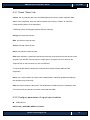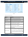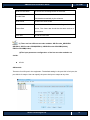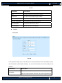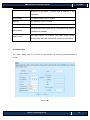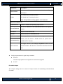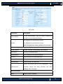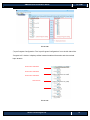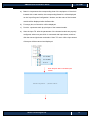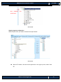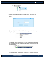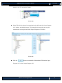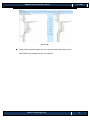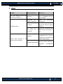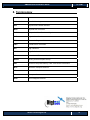
1
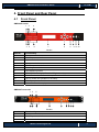
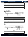
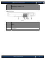
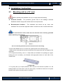
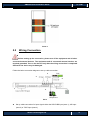
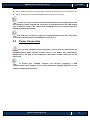
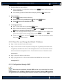
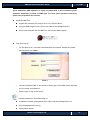
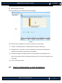
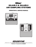
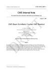
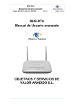
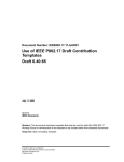
SMP260 Digital Encoder & Transcoder Quick Installation Guide V1.10-W SMP260 Quick Installation Guide V1.10-W Preface About This Document This document provides introductions and guidelines to users about how to install and operate this equipment quickly. Disclaimer Wellav Technologies Ltd. assumes no responsibility for errors or omissions that may appear in this publication. It reserves the right to change this publication at any time without notice. This document is not to be construed as conferring by implication, estoppel, or otherwise any license or right under any copyright or patent, whether or not the use of any information in this document employs an invention claimed in any existing or later issued patent. Intended Readers z Technical Service Engineer z Maintenance Engineer z Test Engineer z Sales Engineer Symbols Definition For the symbols that might appear in this document, the meanings they represent are as the following: Symbol Meaning There is highly potential danger. If it cannot be avoided, it will lead to the deaths or serious injury. There is medium or low potential danger. If it cannot be avoided, it will lead to medium or slight injury. There are potential risks. If ignore these texts, it may cause damage to the device, data loss, equipment performance reduce or unpredictable results. Tips that help you to solve problems or save your time. Wellav Technologies Ltd. 2 SMP260 Quick Installation Guide V1.10-W Remarks. Additional information to the text, in order to emphasize something. Revision History The revision history lists the modification history. The newest one contains all the modifications of the past revision. V1.00: First revision. (Date: Nov 26th, 2012) V1.10: Optimize the document structure. (Date: Nov 22nd, 2012) Wellav Technologies Ltd. 3 SMP260 Quick Installation Guide V1.10-W Contents 1. Safety ............................................................................................................................ 5 2. Check Package and Accessories .................................................................................. 6 3. Physical specifications ................................................................................................... 7 4. 5. 6. 3.1 Physical Specifications ........................................................................................... 7 3.2 Interfaces and Protocols ......................................................................................... 7 Front Panel and Rear Panel .......................................................................................... 8 4.1 Front Panel ............................................................................................................. 8 4.2 Rear Panel ............................................................................................................. 9 Installation Instruction .................................................................................................. 11 5.1 Mounting unit to a 19” rack ................................................................................... 11 5.2 Wiring Connection ................................................................................................ 12 5.3 Power Connection ................................................................................................ 13 Operation Instructions ................................................................................................. 14 6.1 Powering Up & Initializations ................................................................................ 14 6.2 Network Connection Setup ................................................................................... 14 6.2.1 Navigation Keys Operation Instruction ............................................................. 14 6.2.2 Check Out and Change the Default IP Address ............................................... 15 6.2.3 Configuration through NMS.............................................................................. 15 6.3 Quick Configuration on Key Parameters .............................................................. 17 6.3.1 Check “Status” tab............................................................................................ 18 6.3.2 Configure parameters of signal input modules ................................................. 18 6.3.3 Program IN/OUT configuration in “Program Info” tab ....................................... 25 7. FAQ ............................................................................................................................. 32 8. Terminology ................................................................................................................. 33 Wellav Technologies Ltd. 4 SMP260 Quick Installation Guide V1.10-W 1. Safety z To avoid electric-shock hazards, do not open the receiver; refer service to qualified personnel only. z Do not expose the device in the sunlight, and keep it away from the heat source. z Do not block ventilation holes of the device so that air can circulate freely. z Switch the device off whenever it remains out of service for an extended period. z Be sure to turn the device off and disconnect the AC power cord before cleaning the receiver surface. z The apparatus shall be connected the mains socket outlet with a protective grounded connection z The appliance coupler used as the disconnect device shall remain operable Wellav Technologies Ltd. 5 SMP260 Quick Installation Guide V1.10-W 2. Check Package and Accessories The SMP260 Encoder package includes the following accessories: z Base Unit x1 z Power cord x1 z Ground wire x1 z Audio Cable x6 z NMS Installation Disc x1 z BNC Cable x4 z RCA Cable x3 z User guide disc x1 The SMP260 Transcoder package includes the following accessories: z Base Unit x1 z Power cord x1 z Ground wire x1 z NMS Installation Disc x1 z BNC Cable x1 z User guide disc x1 Please contact the supplier if it’s inconsistent with the actual package. Wellav Technologies Ltd. 6 SMP260 Quick Installation Guide V1.10-W 3. Physical specifications 3.1 Physical Specifications Items Power Index 90V-260VAC, 50/60Hz Power Consumption 125W Size 1RU Dimension 482mm x44mm x 393mm Net Weight 5Kg Gross Weight 7.5Kg 3.2 Interfaces and Protocols Inputs IP input ASI input Interface: RJ45 Interface: BNC, 75Ω Max input bit rate: 1000Mbps TS package length:188/204 Protocol: UDP/RTP Max bit rate: 120 Mbps (per TS) Input processing: Up to 12 Sockets, max at 72 Mbps per socket Outputs SDI/CVBS input HDMI input Interface: BNC Compatible with HDCP IP output ASI output Interface: RJ45 Interface: BNC, 75Ω Max input bit rate: 1000Mbps TS package length: 188 Protocol: UDP/RTP Max bit rate: 120 Mbps (per TS) Input processing: Up to 12 Sockets, max at 72 Mbps per socket. Wellav Technologies Ltd. 7 SMP260 Quick Installation Guide V1.10-W 4. Front Panel and Rear Panel 4.1 Front Panel SMP260-Encoder 1 2 3 4 5 6 7 8 9 10 11 12 Pic-4-1 Item No. Functionality 1 Power status indicator 2 ASI/IP input status indicator 3 Input status indicator 4 Alarm status indicator 5 ASI/IP output status indicator 6 Encoding status indicator 7 LED displaying screen 8 KEY PADS, including Up/Down/Left/Right arrow keys 9 Menu. To enter the menu and the quit function of the sub menus. 10 OK. To confirm the operation in the setup. 11 ESC. The quit function of the menu. 12 Reset. To reboot the equipment. SMP260-Transcoder 1 2 3 5 4 5 6 7 8 9 10 11 Pic-4.2 Item No. Functionality 1 Power status indicator 2 ASI/IP input status indicator 3 Alarm status indicator Wellav Technologies Ltd. 8 SMP260 Quick Installation Guide V1.10-W 4 ASI/IP output status indicator 5 Transcoding status indicator 6 LED displaying screen 7 KEY PADS, including Up/Down/Left/Right arrow keys 8 Menu. To enter the menu and the quit function of the sub menus. 9 OK. To confirm the operation in the setup. 10 ESC. The quit function of the menu. 11 Reset. To reboot the equipment. 4.2 Rear Panel SMP260 Encoder-SDI/CVBS 1 2 1 3 4 5 6 7 Pic-4-3 Item No. Functionality 1 SDI/CVBS IN (total 6 SDI/CVBS inputs on this model.) 2 ASI IN 3 Balance/Unbalance Audio In 4 ASI OUT 5 MANAGEMENT: 100BaseTX,RJ45 6 TS/IP IN/OUT 7 POWER There 6 same SDI/CVBS ports and 6 same Balance/Unbalance port in the equipment. SMP260 Encoder-HDMI 1 2 3 4 5 6 Pic-4-4 Item No. Functionality 1 HDMI IN (total 12 HDMI inputs on this model.) 2 ASI IN Wellav Technologies Ltd. 9 SMP260 Quick Installation Guide V1.10-W 3 ASI OUT 4 MANAGEMENT: 100BaseTX, RJ45 5 TS/IP IN/OUT 6 POWER SMP260 Transcoder 1 2 3 4 5 6 Pic-4-5 Item No. Functionality 1 Equipped transcoding modules 2 ASI IN 3 ASI OUT 4 MANAGEMENT: 100BaseTX, RJ45 5 TS/IP IN/OUT 6 POWER Wellav Technologies Ltd. 10 SMP260 Quick Installation Guide V1.10-W 5. Installation Instruction 5.1 Mounting unit to a 19” rack When selecting the installation site, try to comply with the following: z Protective Ground - The protective ground lead of the building's electrical installation should comply with national and local requirements. z Environmental Condition - The installation site should be dry, clean, and ventilated. Do not use this equipment where it could be at risk of contact with water. To avoid electric shock, make sure the rack has been correctly grounded before switching on the device. PIC-5-1 PIC‐5.1‐1 Grounding Jackscrew (must be connected to the rack housing) To mount the SMP260 unit to a 19”/42U rack, please perform the following steps: 1. Make sure the mounted rack surface is stable and can support the size and weight of this equipment. 2. For single unit mounting, use an “L” shape slide (not included in the package) to support holding the unit if necessary, and fastened with appropriate screws to each side of the chassis’ rails. L-shape slide 3. For group pile up (no space between each unit), the unit should be placed on a flat holding bracket. No more than 5 units for each group, and leave at least one unit space between each group to ensure good air ventilation. Wellav Technologies Ltd. 11 SMP260 Quick Installation Guide V1.10-W PIC-5-2 5.2 Wiring Connection 1 Before setting up the connection, please turn off the equipment and all other connected external devices. The equipment and all connected external devices are required grounded. Turn on the devices only after the wiring connection is completed. Otherwise the device may be damaged. Follow the below connection diagram to set up cable connection: 3 2 4 1 5 PIC-3 z Set up cable connection for input signal: either the SDI/CVBS input (area 1), ASI input (area 2) or TS/IP input (area 4) Wellav Technologies Ltd. 12 SMP260 Quick Installation Guide V1.10-W z Set up cable connection for output signal: either through ASI (area 3) or TS/IP (area 4) z Set up connection for network management control: shown in area 5. In order to ensure a smooth communication between the management PC and the equipment, please separate the connection of management port and TS/IP output port to different switch. The switch with management port connected should be without large data processing. The TS/IP port can work for input and output simultaneously. User only needs to connect one RJ45 cable to the TS/IP port of the device. 5.3 Power Connection Connect this equipment only to the power sources that are identified on the equipment-rating label normally located close to the power inlet connector(s). Always pull on the plug or the connector to disconnect a cable. Never pull on the cable itself. To protect your valuable interests and services, equipping a UPS (Uninterrupted Power Supply) and an AVR (Automated Voltage Regulator) to the system is highly recommended. Wellav Technologies Ltd. 13 SMP260 Quick Installation Guide V1.10-W 6. Operation Instructions 6.1 Powering Up & Initializations Before powering-up the device, make sure that all cabling is correctly connected (refer to chapter 5.2). The device is correctly connected to the power inlet and grounded. Switch on the equipment through the back power switch, the unit is powered up and start the initialization. The LCD screen is lighted up, and display information as following: SMP260 Setting subboard1…… The initialization takes about 20 seconds to complete. If the unit fails to initialize and hangs at the “booting” stage, swtiching off the device and then powering up again may help. If the device still fails to initialize, please contact your service representative for help. The input/output indicator LEDs turn (red? Off?..) after successful initialization because of signal unlocking. After configuration on the device, corresponding LEDs shall show correct status. 6.2 Network Connection Setup 6.2.1 Navigation Keys Operation Instruction Use the 6 navigation keys on front panel: Up / Down / Left / Right / Menu / Ok to enter the configuration menu. z Enter “Menu”: Press “MENU” button to enter main menu. Wellav Technologies Ltd. 14 SMP260 Quick Installation Guide V1.10-W z Exit Menu/Back to parent Menu Upon completion of configuration settings, press “MENU” button until you go back to the Parent Menu. z z You can also go back to Parent Menu directly by pressing “ESC” button once. Enter Sub-Menu Press MENU button to enter main menu. Select a sub-menu by pressing arrow UP and arrow DOWN button. Press OK button on the selected sub-menu. To change parameter Step 1: Enter main menu by pressing MENU button. Step 2: Scroll sub-menu by pressing arrow UP and arrow DOWN button, and press OK button to change the selected sub-menu. Step 3: To change parameter settings, press arrow RIGHT and arrow LEFT button to move the cursor in which change must be made. Press arrow UP button and arrow DOWN to input / select an appropriate setting, then press OK button to save. 6.2.2 Check Out and Change the Default IP Address z Step 1: check out the IP on the LCD screen. z Step 2: use the button on the front panel to change the IP, gateway and subnet mask. The gateway should be the same as the management PC’s. The subnet mask should be the same as the management PC’s s. The IP and the server’s IP should be in the same section. z Step 3: reboot the device to take effect. z Step 4: ping the new IP on PC to check whether the SMP260 can connect to the management PC. 6.2.3 Configuration through NMS Accessing the equipment through NMS can be very convenient for remote configuration of the equipment. Relative to the front panel settings, NMS operation can provide a more user-friendly man-machine interface, and less limits in space. For Wellav Technologies Ltd. 15 SMP260 Quick Installation Guide V1.10-W quick installation, NMS operation is highly recommended. In this installation guide, operation instruction is based on NMS style. For front panel operation instruction, please refer to product user manual. z z Install the NMS Tool Unpack the accessory CD, and put it on a PC CD/DVD driver; Copy the NMS program on the CD to any folder of the management PC; Use mouse to double click the NMS icon and run the NMS program. First Time Log On o For first time log on, User Name and Password are required. Default User Name and Password are “admin”. PIC-6-1 o Choose “Remember Me” if user wants to directly log on the NMS without inputting the user name and password. o Select “Login” to log on the device. Possible reasons for unsuccessful log on: z IP address/ network mask/gateway don’t match with the management PC’s z User name/password is wrong z Wrong NMS version Wellav Technologies Ltd. 16 SMP260 Quick Installation Guide V1.10-W z Main Interface Introduction After successful log on, the following screen will display: Pic-6-2 The interface can be divided into four areas according to its functionality. (1) Toolbar. It includes shortcut to change password and save setting etc. (2) Equipment list. If more than a piece of equipment is connected to the NMS, the equipment will be listed in this area by its IP address. (3) Parameter setting and configuration area. The parameters of the equipment are shown and configured here by selecting different tabs. This is the main operation area of the NMS. (4) Event information window. 6.3 Quick Configuration on Key Parameters Wellav Technologies Ltd. 17 SMP260 Quick Installation Guide V1.10-W 6.3.1 Check “Status” tab “Status” tab: by selecting this item, the NMS displays the current system operation data status of the equipment. User can swtich between tab under the “Status” to check the current working status of the equipment ①Different colors of histogram indicate different meaning: Orange: the total input bit rate; Blue: the effective input bit rate; Yellow: the total output bit rate; Green: the effective output bit rate; Red: alarm indicator, it means the actual output bit rate (it’s proportional to the amount of the programs you transfer from input port to output port in ‘Program Info’) is more than the output bit rate of some channel you set in sub-board. ②Communicate Status indicates the communication status between NMS and the equipment. Green: the communication is normal. All the parameters in NMS are updated according to the equipment synchronously. Red: the communication is abnormal. The parameters in NMS may be not updated in time. You need check the network connection and restart the NMS. 6.3.2 Configure parameters of signal input modules CVBS/SDI IN SD-Encoder_SDI/CVBS (MPEG-2) module Wellav Technologies Ltd. 18 SMP260 Quick Installation Guide V1.10-W Pic-6-3 Following are the key parameters: Parameters Description Channel Select a channel to configure its parameters. Video Source To select the correct video source for the input. Audio Source To select the correct audio source for the input. Encode Mode Select CBR or VBR for the encoding mode. Video Max Encode Rate To set the Max encode rate for VBR mode. The range of max encode rate is 2000 ~ 15000 Kbps. To set the Min encode rate for VBR mode. The range of Video Min Encode Rate min encode rate is 2000 ~ 15000 Kbps. Note: the min encode rate must be smaller than the max encode rate. To set the encode rate for both VBR mode and VBR mode. The range is 2000 ~ 15000 Kbps. Note: The Video Encode Rate values of the video encode rate should be between the max encode rate and the mix encode rate in CBR mode. Wellav Technologies Ltd. 19 SMP260 Quick Installation Guide V1.10-W Audio Encode Rate Encode Rate Audio Mode To choose the encoding bitrate for the audio. The total encode rate of video and audio contents. Calculated automatically by the software. To select the audio mode To select correct frame rate according to the input Frame Rate source. The frame rate should be the same as that of input source. GOP Size To edit the GOP size (1) There are four different encoder modules: SD-Encoder_SDI/CVBS (MPEG-2), SD-Encoder-CVBS(MPEG-2), HD/SD-Encoder-SD/CVBS(H.264), HD-Encodr-HDMI(H.264). (2)The input paraments configuration of the four encoder modules are similar. z ASI IN ASI module There are four ASI port in the equipment. The default setting is: the port 1&2 is for input; the port 3&4 is for output. User can specify the port to be input or output at any time. Wellav Technologies Ltd. 20 SMP260 Quick Installation Guide V1.10-W Pic-6-4 Parameters Description Type Set each ASI port to be Input or Output. Packet Size Set 188 or 204 packet size for outputs. Mode Set ASI port into CBR or VBR for output. Constant Rate(Mbit) Set constant bit rate for ASI output. Max Rate(Mbit) Set max bit rate for ASI output. Min Rate(Mbit) Set min bit rate for ASI output. TS/IP IN z IP module Pic-6-5 In the ‘System’ setting menu, user need to set correct parameters for the IP module such as the IP address, subnet Mask, Gateway, etc, so that the module can work normally in the network. Parameters IP Address Description Set IP address of IP module. The IP address of IP module is used for communication with basic unit of the equipment that Wellav Technologies Ltd. 21 SMP260 Quick Installation Guide V1.10-W should be in the same IP section with IP address of the equipment. Subnet Mask Set Subnet Mark of the IP module Gateway Set Gateway of the IP module MAC Address MAC address of the IP module Speed Mode IGMP Version Set RJ45 connection speed mode. The speed mode support 100Mbit and 1000Mbit. Set IGMP Version for multicast. The IGMP version setting should match the IGMP version of the switch in the network. IP module-Input The “Input” setting menu is to set the IP input function for receiving multicast/unicast IP stream. Pic-3.3-39 Wellav Technologies Ltd. 22 SMP260 Quick Installation Guide V1.10-W Parameters ChannelSelect Description In this ‘ChannelSelect’, user can select a channel to configure its parameters. On: enable the IP receiving function. Enable Off: disable the IP receiving function. Note: this parameter setting applies to all channels. Channel configuration EnableChannel SourceIPAddress Enable or disable corresponding input channel Set the IP address of the multicast/unicast that are going to receive SourcePort Set port of multicast/unicast Protocol Select UDP/RTP for multicast/unicast ColPortMatching If the output IP stream quality looks not as good as the input stream, user can select to ‘Enable’ these two options then to RowPortMatching enable the FEC function. The bigger values it is, the stronger capabilities it has to correct FEC Parameter the data mistakes. But the FECL and FECD should be less than 100. z Configure parameters of signal output modules z ASI OUT The ASI output parament configuraion is introduced in page22. z IP OUT IP module-Output The “Output” setting menu is to set the IP output function for transmitting multicast/unicast IP stream. Wellav Technologies Ltd. 23 SMP260 Quick Installation Guide V1.10-W Pic-3.3-40 Parameters Description In this ‘ChannelSelect’, user can select a channel to ChannelSelect configure its transmitting parameters. On: enable the IP transmission function. Enable Off: disable the IP transmission function. Note: this parameter setting applies to all channels. Channel configuration EnableChannel Enable or disable corresponding output channel SourcePort Set port of multicast/unicast DestIPAddress Set IP address of the multicast/unicast. Protocol Select UDP/RTP for multicast/unicast EncapNumTSPackets Rang 1~7. (Num 7 is recommended) TSPacketSize Select 188/204 TS packet size Select one service type as your requirement. Type TypeofService including: Normal, Min delay, Monetary cost, Max reliability, Max Throughput. Bitrate Parameter Mode Mode includes: CBR/VBR Wellav Technologies Ltd. 24 SMP260 Quick Installation Guide V1.10-W ConstantRate(Mbit) Set constant bitrate for output MaxRate(Mbit) Set max bitrate for output MainRate(Mbit) Set min bitrate for output 6.3.3 Program IN/OUT configuration in “Program Info” tab Operation Buttons a) Transfer button: to transfer the selected stream/PID from the input program window to the output program window. b) Set button: to apply the changes to the NMS. The setting will lose if the NMS is close or the equipment is powered off. c) To obtain/refresh the current parameters status of the equipment mainboard. d) To save the configuration. The saved data can be kept after NMS is closed or the equipment power off. e) Import a configuration file. f) Export the current settings of the equipment and save as a configuration file. g) To eliminate all the settings in the input and output window. Input program configuration Wellav Technologies Ltd. 25 SMP260 Quick Installation Guide V1.10-W Pic-3.3-20 ①Input Program Configuration: The “Input Program Configuration” is on the left side of the “Program Info” window. It displays all the inserted modules information and the received input streams. SD‐Encoder CVBS Slot1 SD‐Encoder CVBS Slot2 SD‐Encoder CVBS Slot3 ASI Interface Pic-3.3-21 Wellav Technologies Ltd. 26 SMP260 Quick Installation Guide V1.10-W a) Board1~4 represents the corresponding slots of the equipment. If the slot is inserted with a card module, the corresponding Board No. will be displayed on the “Input Program Configuration” window, and the name of the inserted module will be displayed after the Board No. b) For empty slot, no Board No. will be displayed. c) Port No.: represents each physical port of the inserted module. d) Scan the input TS: after the parameters of the inserted module are properly configured, select one port which is connected with input stream, and then click the mouse right button and select “Scan TS” menu. All the input stream of that port will be scanned and displayed. Scan the port that is fed with input stream Wellav Technologies Ltd. 27 SMP260 Quick Installation Guide V1.10-W Scan completes and receives data Pic-3.3-22 Output program configuration Select the port which you want to transmit the output stream. Pic-3.3-41 Select a TS stream, click the mouse right button. In the pop-up menu, select “Add TS”. Wellav Technologies Ltd. 28 SMP260 Quick Installation Guide V1.10-W Pic-3.3-42 Input the “Original Network ID” and “TS ID” for the channel, and click the “Add” button. Pic-3.3-43 The input “Original Network ID” and “TS ID” will be assigned to the selected output TS (channel). Pic-3.3-44 To change the “Original Network ID” and “TS ID”, use the left mouse button to click the TS (channel) name when it is being selected. Then the TS (channel) name will be in editable status. Pic-3.3-45 To delete the inserted “Original Network ID” and “TS ID”, click the right mouse Wellav Technologies Ltd. 29 SMP260 Quick Installation Guide V1.10-W button on the TS, and select “Delete”. Pic-3.3-46 Select TS which is going to be transmitted on the left hand side “Input Program Info” window, and select the port, TS (channel) which are going to carry the transmission on the right hand side “Output Program Info” window. Pic-3.3-47 Click the button to set transfer of the selected TS from the “Input Program Info” to the “Output Program Info”. Wellav Technologies Ltd. 30 SMP260 Quick Installation Guide V1.10-W Pic-3.3-48 Follow above operation steps, user can set the selected input stream to be transmitted at any assigned output TS (channel). Wellav Technologies Ltd. 31 SMP260 Quick Installation Guide V1.10-W 7. FAQ Problem Possible Reasons What to do Check whether the power cord is plugged into the power socket. The LCD display on the front No power. panel does not light up. Parameters are not Check the properly configured. configuration Check the source and other factors that affect the signal reception. No signal No Signal output The cables connected IP setting Cannot have access to equipment through NMS the parameters are not Check the connection and make sure the connection is well. Check whether the management PC IP and the equipment IP have been set to be in same section. Make sure the cable is good one and connect well to the Network cable problem equipment management port. Wellav Technologies Ltd. 32 SMP260 Quick Installation Guide V1.10-W 8. Terminology A-Z Abbreviation Specific Meaning ASI Asynchronous Serial Interface BNC Bayonet Nut Connector CVBS Composite Video Broadcast Signal DVB Digital Video Broadcast EPG Electronic Program Guide FEC Forward Error Correction HD High Definition HDMI High Definition Multimedia Interface ITU International Telecommunications Union MPEG Moving Pictures Experts Group PID Personal Computer Memory Card International Association RTP Real-time Transport Protocol SD Standard Definition TS Transport Stream UDP User Datagram Protocol Wellav Technologies Ltd. 33