1
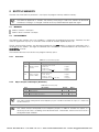
Motors I Automation I Energy I Transmission & Distribution I Coatings SoftPLC CFW500 User’s Manual Phone: 800.894.0412 - Fax: 888.723.4773 - Web: www.ctiautomation.net - Email: [email protected] SoftPLC Manual Series: CFW500 Language: English Document Number: 10002299985 / 01 Publication Date: 06/2015 Phone: 800.894.0412 - Fax: 888.723.4773 - Web: www.ctiautomation.net - Email: [email protected] SUMMARY ABOUT THE MANUAL ..................................................................................................................................... 5 ABBREVIATIONS AND DEFINITIONS ......................................................................................................... 5 NUMERICAL REPRESENTATION ............................................................................................................... 5 1 INTRODUCTION TO SOFTPLC ................................................................................................................ 6 1.1 2 SYMBOL OF THE DATA TYPES ........................................................................................................ 6 SOFTPLC MEMORY ................................................................................................................................. 7 2.1 MEMORY ............................................................................................................................................ 7 2.2 DATA MEMORY ................................................................................................................................. 7 2.2.1 Constants.................................................................................................................................... 7 2.2.2 Physical Inputs and Outputs (Hardware) ................................................................................. 7 2.2.3 Volatile Markers (Variables) ...................................................................................................... 8 2.2.4 System Markers ......................................................................................................................... 8 2.2.5 Parameters ............................................................................................................................... 10 2.3 MODBUS .......................................................................................................................................... 11 2.3.1 Modbus protocol SoftPLC addresses ................................................................................... 11 2.3.2 Protocol..................................................................................................................................... 11 3 RESUME OF THE FUNCTION BLOCKS ................................................................................................ 12 3.1 CONTACTS ...................................................................................................................................... 12 3.1.1 Normally Open Contact – NO CONTACT ............................................................................... 12 3.1.2 Normally Closed Contact – NC CONTACT ............................................................................ 12 3.1.3 AND Logic with Contacts ........................................................................................................ 12 3.1.4 OR Logic with Contacts .......................................................................................................... 12 3.2 COILS ............................................................................................................................................... 13 3.2.1 Normal Coil - COIL ................................................................................................................... 13 3.2.2 Negated Coil – NEG COIL........................................................................................................ 13 3.2.3 Set Coil – SET COIL ................................................................................................................. 13 3.2.4 Reset Coil – RESET COIL ........................................................................................................ 13 3.2.5 Positive Transition Coil – PTS COIL ....................................................................................... 13 3.2.6 Negative Transition Coil – NTS COIL ..................................................................................... 13 3.3 MOVEMENT BLOCKS ..................................................................................................................... 13 3.3.1 Speed and/or Torque Reference – REF ................................................................................. 13 3.4 PLC BLOCKS ................................................................................................................................... 14 3.4.1 Timer – TON .............................................................................................................................. 14 3.4.2 Incremental Counter – CTU .................................................................................................... 14 3.4.3 Proportional-Integral-Derivative Controller – PID ............................................................... 14 3.4.4 Low-pass or High-pass Filter – FILTER ................................................................................. 15 3.5 CALCULATION BLOCKS ................................................................................................................ 15 3.5.1 Comparator – COMP ............................................................................................................... 15 3.5.2 Math Operation – MATH .......................................................................................................... 15 3.5.3 Math Function - FUNC ............................................................................................................. 16 3.5.4 Saturator – SAT ........................................................................................................................ 16 3.6 TRANSFER BLOCKS ....................................................................................................................... 17 3.6.1 Data Transfer – TRANSFER .................................................................................................... 17 3.6.2 Conversion from Integer (16 bits) to Floating Point – INT2FL ............................................. 17 3.6.3 User Fault or Alarm Generator - USERERR .......................................................................... 17 3.6.4 Convert from Floating Point to Integer (16 bits) – FL2INT ................................................... 18 3.6.5 Indirect Data Transfer – IDATA ............................................................................................... 18 3.6.6 Multiplex – MUX ....................................................................................................................... 18 3.6.7 Demultiplexer – DMUX ............................................................................................................ 19 4 1. INVERTER PARAMETER SETTINGS ................................................................................................. 20 4.1 4.2 SYMBOLS FOR PROPERTY DESCRIPTION .................................................................................. 20 CFW500 CONFIGURATION PARAMETERS ................................................................................... 20 Phone: 800.894.0412 - Fax: 888.723.4773 - Web: www.ctiautomation.net - Email: [email protected] 4.3 SOFTPLC EXCLUSIVE PARAMETERS ........................................................................................... 21 P1000 – SOFTPLC STATUS ........................................................................................................................... 21 P1001 – SOFTPLC COMMAND ....................................................................................................................... 21 P1002 – SCAN CYCLE TIME ........................................................................................................................... 22 P1010 TO P1059 – SOFTPLC USER PARAMETERS ......................................................................................... 22 5 SUMMARY OF THE WLP MAIN FUNCTIONS....................................................................................... 23 5.1 5.2 5.3 5.4 5.5 5.6 5.7 5.8 5.9 6 PROJECT – NEW.............................................................................................................................. 23 PROJECT – OPEN ............................................................................................................................ 23 PROJECT – PROPERTIES ............................................................................................................... 23 VIEW – COMPILATION INFORMATION .......................................................................................... 24 VIEW – USER PARAMETER CONFIGURATION ............................................................................. 24 CONSTRUCT – COMPILE ............................................................................................................... 25 COMMUNICATION – CONFIGURATION ........................................................................................ 25 COMMUNICATION – DOWNLOAD ................................................................................................. 26 COMMUNICATION – UPLOAD ....................................................................................................... 26 ALARMS, FAULTS AND POSSIBLE CAUSES ...................................................................................... 28 Phone: 800.894.0412 - Fax: 888.723.4773 - Web: www.ctiautomation.net - Email: [email protected] ABOUT THE MANUAL This manual provides the required information for the operation of the CFW500 frequency inverter using the user’s programming module, called SoftPLC. This manual must be used together with the user’s manual of the CFW500 and WLP software. ABBREVIATIONS AND DEFINITIONS PLC CRC RAM WLP USB Programmable Logic Controller Cycling Redundancy Check Random Access Memory Ladder Language Programming Software Universal Serial Bus NUMERICAL REPRESENTATION Decimal numbers are represented by means of digits without suffix. Hexadecimal numbers are represented with the letter 'h' after the number. Phone: 800.894.0412 - Fax: 888.723.4773 - Web: www.ctiautomation.net - Email: [email protected] 1 INTRODUCTION TO SOFTPLC The SoftPLC is a resource that adds the functionalities of a PLC to the CFW500, providing the product with flexibility and allowing the user to develop its own applications (user’s programs). The main SoftPLC characteristics are: Programming in “Ladder Language” using the WLP software. Access to all Parameters and I/Os of the CFW500. 50 configurable parameters for the user’s use. PLC, Mathematical and Control Blocks On-line transfer and monitoring of the software application via Serial/USB interface. Transfer of the application software installed on the CFW500 to the PC with password restriction. Storage of the software application on the FLASH memory board. Execution directly on the RAM. 1.1 %KW %KF %MX %MW %MF %SX %SW %IX %IW %QX %QW %UW %UW %PD SYMBOL OF THE DATA TYPES word-type constants (16 bits) float type constants (32 bits, floating point) bit markers word markers (16 bits) float markers (32 bits, floating point) system bit markers system word markers (16 bits) digital Inputs analog inputs (16 bits) digital outputs analog outputs (16 bits) user parameters (16 bits) user parameters (16 bits) drive parameter (16 bits) Phone: 800.894.0412 - Fax: 888.723.4773 - Web: www.ctiautomation.net - Email: [email protected] 2 SOFTPLC MEMORY The total size of the SoftPLC parameter is 7684 bytes for program memory and data memory. NOTE! The SoftPLC application is stored in the memory of the plug-in used at the moment of download. Therefore, if the plug-in is changed, it will be necessary to download the application again. 2.1 MEMORY SoftPLC function: 7684 bytes SoftPLC User Parameter: 508 bytes 2.2 DATA MEMORY The SoftPLC data memory area (user variables) is shared with the programming memory. Therefore, the total size of an application may vary as a function of the number of variables applied by the user. The bit, word and float markers are allocated according to the LAST address used on the application, that is, the longer the last address, the larger the allocated area. Therefore, it is recommended to use the markers in a SEQUENTIAL manner. The word and float constants do also use program memory space. 2.2.1 Constants Table 2.1: Constant Memory Map Sym. 2.2.2 Description %KW Word Constants (16 bits) %KF Float Constants (32 bits – IEEE) Bytes It depends on the number of different word constants. E.g.: If there were used: - %KW: 327 = 2 bytes - %KW: 5; 67 = 4 bytes - %KW: 13; 1000; 13; 4 = 6 bytes It depends on the number of different float constants. E.g.: If there were used: - %KF: -0,335 = 4 bytes - %KF: 5,1; 114,2 = 8 bytes - %KF: 0,0; 115,3; 0,0; 13,333 = 12 bytes Physical Inputs and Outputs (Hardware) Table 2.2: I/O Memory Map Sym. %IX %QX %IW %QW Description Digital Inputs Digital Outputs Analog Inputs/Frequency Analog Outputs/Frequency Range 1 ... 8 1 ... 5 1 ... 4 1 ... 3 Bytes 2 2 8 6 NOTE! The %IW4 marker corresponds to the frequency input. In order to activate this input, it is necessary to set P0246 to 1. NOTE! The %QW3 marker corresponds to the frequency output. In order to activate this output, it is necessary to set P0257 according to the desired function. Furthermore, note that the DO2 circuit is configured in open collector. Phone: 800.894.0412 - Fax: 888.723.4773 - Web: www.ctiautomation.net - Email: [email protected] NOTE! The values of the Analog/Frequency Inputs (%IW) and of the Analog/Frequency Outputs (%QW) respectively read and written via SoftPLC respect their gains (P0232, P0237, P0242, P0247: %IW1−%IW4 and P0252, P0255, P0258: %QW1−%QW3) and offsets (P0234, P0239, P0244, P0249: %IW1−%IW4). NOTE! The values read or written via SoftPLC obey the following rules, respecting the parameters related to the analog input and output signal types (P0233, P0238, P0243: %IW1−%IW3 and P253, P256: %QW1−%QW2): Option: 0 to 10V/20mA 0V or 0mA =0 10V or 20mA = 32767 Option: 4 to 20mA 4mA = 0 20mA = 32767 Option: 10V/20mA to 0 10V or 20mA = 0 0V or 0mA = 32767 Option: 20 to 4mA 20mA = 0 4mA = 32767 2.2.3 Volatile Markers (Variables) They consist of variables that can be applied by the user to execute the applicative logics. They can be bit markers (1 bit), word markers (16 bit) or float markers (32 bit – IEEE). Table 2.3: Volatile Marker Memory Map Sym. Description Range %MX Bit Markers 5000 ... 6099 %MW Word Markers 8000 ... 8199 %MF Float Markers 9000 ... 9199 Bytes It depends on the last used marker. They are organized in byte pairs. E.g.: - last marker: %MX5000 = 2 bytes - last marker: %MX5014 = 2 bytes - last marker: %MX5016 = 4 bytes - last marker: %MX5039 = 6 bytes It depends on the last used marker. E.g.: - last marker: %MX8000 = 2 bytes - last marker: %MX8001 = 4 bytes - last marker: %MX8007 = 16 bytes It depends on the last used marker. E.g.: - last marker: %MX9000 = 4 bytes - last marker: %MX9001 = 8 bytes - last marker: %MX9007 = 32 bytes NOTE! In order to minimize the application size, use the markers in a sequential manner. E.g.: Bit markers: %MX5000, %MX5001, %MX5002, ... Word markers: %MW8000, %MW8001, %MW8002, ... Float markers: %MF9000, %MF9001, %MF9002, ... 2.2.4 System Markers They consist of special variables that allow the user to read and change inverter data that may or may not be available in the parameters. They can be: system bit markers (1 bit) or system word markers (16 bits). Phone: 800.894.0412 - Fax: 888.723.4773 - Web: www.ctiautomation.net - Email: [email protected] Table 2.4 (a): Memory Map for the Odd System Bits – Writing/Command Sym. Type %SX Description System Bits Writing/Command (odd) Range 3000 ... 3040 3001 General Enabling 3003 Run/Stop 3005 Speed Direction 3007 JOG 3009 LOC/REM 3011 Fault reset 3021 Activates the Second Ramp Bytes 4 bytes 0: It disables the inverter completely, interrupting the supply for the motor. 1: It enables the inverter, allowing the motor operation. 0: It stops the motor with deceleration ramp. The motor rung according to the acceleration ramp until reaching the speed reference value. 0: It runs the motor in the counterclockwise direction. 1: It runs the motor in the clockwise direction. 0: It disables the JOG function. 1: It enables the JOG function. 0: The inverter goes to the local situation. 1: The inverter goes to the remote situation. 0: No function. 1: If in fault condition, it resets the inverter. NOTE: When this command is executed, the inverter and the SoftPLC Application are reinitialized. This is also valid for reset via keypad. 0: The values for the motor acceleration and deceleration are those from the first Ramp (P0100 and P0101). 1: The values for the motor acceleration and deceleration are those from the second Ramp (P0102 and P0103). Note: Program P0105 in 6 in order to enable the selection via SoftPLC. Table 2.4 (b): Memory Map for the Even System Bit – Reading/State Sym. Type %SX Description System Bits Reading/State (Even) Range 3000 ... 3040 Bytes 4 bytes 0: General enabling is not active. 1: General enabling is active and the inverter is ready to run the motor. 0: The motor is stopped. 1: The inverter is driving the motor at the set point speed, or executing either the acceleration or the deceleration ramp. 0: The motor is rotating counterclockwise. 1: The motor is rotating clockwise. 0: JOG function inactive. 1: JOG function active. 0: Inverter in local mode. 1: Inverter in remote mode. 0: Inverter is not in fault state. 1: Some fault registered by the inverter. Note: The number of the fault can be read through parameter P0049 – Current Fault. 0: No undervoltage. 1: With undervoltage. 0: In manual mode (PID function). 1: In automatic mode (PID function). 0: Inverter is not in an alarm condition. 1: Inverter is in an alarm condition. Note: The number of the alarm can be read by means of parameter P0048 – Current Alarm. 0: Inverter operating normally. 1: Inverter in configuration state. It indicates a special condition when the inverter cannot be enabled: - Executing the self tuning routing. - There is a parameter setting incompatibility. Note: Parameter P0047 shows the cause of the parameter setting incompatibility. 0: It indicates that the first Ramp is active. 1: It indicates that the second Ramp is active. 3000 General Enabling 3002 Motor Running (RUN) 3004 Speed Direction 3006 JOG 3008 LOC/REM 3010 In Fault 3012 Undervoltage 3014 PID Operation Mode 3016 Alarm Condition 3018 In Configuration Mode 3020 Active Ramp 3032 3034 3036 3038 Start key (1) Stop key (0) Speed direction key () Local/Remote key 0: Not pressed. 1: Pressed during 1 scan cycle 3040 JOG key 0: Not pressed. 1: Pressed. Phone: 800.894.0412 - Fax: 888.723.4773 - Web: www.ctiautomation.net - Email: [email protected] Table 2.5: Memory Map for the Even System Word Markers Sym. %SW Description Range System Words 3300 ... 3324 Reading Markers/Status (Even) 3300 Motor speed [13 bits] 3302 Motor synchronous speed [rpm] 3304 Motor speed [rpm] 3306 Speed reference [rpm] 3308 Alarm 3310 Fault 3320 Inverter rated current [A x10] 3322 Unfiltered motor current (P003) [A x10] 3324 Unfiltered motor torque [% x10] Bytes 48 bytes NOTE! The system word markers %SW3300 use a 13 -bits resolution (8192 0 to 8191), which the motor synchronous speed. Thus, if the speed reference via “Reference” block (%SW3301) is 4096 for a VI pole motor (this means a synchronous speed of 1200 rpm), the motor will run at 600 rpm. NOTE! Equation for the calculation of the motor speed in rpm: Speed in rpm = synchronous speed in rpm x speed in 13 bits 8192 NOTE! Equation for the calculation of the motor speed in Hz: Speed in Hz = synchronous frequency in Hz (P0403) x speed in 13 bits 8192 2.2.5 Parameters The parameters from P1010 to P1059 appear on the keypad only when there is a valid application (user program) in the memory, i.e., when P1000 > 0. Table 2.6: Parameter Memory Map Sym. %PD Description System Parameters (refer to the CFW500 manual) SoftPLC Parameters P1000: SoftPLC Status [Read-only parameter] %PW P1001: SoftPLC Command %UW P1002: Scan Cycle Time [ms] [Read-only parameter] User Parameters Range Bytes 0... 999 1000 ... 1059 6 bytes 0: No application 1: Install. Applic. 2: Incompat. App. 3: App. Stopped 4: App. Running 0: Stop Program 1: Run Program 2: Delete Program 1010 ... 1059 100 bytes Phone: 800.894.0412 - Fax: 888.723.4773 - Web: www.ctiautomation.net - Email: [email protected] 2.3 2.3.1 MODBUS Modbus protocol SoftPLC addresses Table 2.7: SoftPLC x Modbus Address Range Sym. %IX %QX %IW %QW Description Digital Inputs Digital Outputs Analog Inputs/Frequency Analog Outputs/Frequency SoftPLC 1 ... 8 1 ... 5 1 ... 4 1 ... 3 MODBUS 2201...2208 2401...2405 2601...2603 2801...2802 NOTE! The %IW4 marker corresponds to the frequency input. In order to activate this input, it is necessary to set P0246 to 1. NOTE! The %QW3 marker corresponds to the frequency output. In order to activate this output, it is necessary to set P0257 according to the desired function. Furthermore, note that the DO2 circuit is configured in open collector. NOTE! All the other data types have the user addresses (SoftPLC) equal to the Modbus addresses. E.g.: %PD0100 = Modbus address 100; %MX5000 = Modbus address 5000; %SW3308 = Modbus address 3308. 2.3.2 Protocol Refer to the RS232/RS485 Serial Communication manual, at the Modbus Protocol chapter. Phone: 800.894.0412 - Fax: 888.723.4773 - Web: www.ctiautomation.net - Email: [email protected] 3 RESUME OF THE FUNCTION BLOCKS This chapter contains a summary of the function blocks that are available for the user programming. 3.1 CONTACTS They send to the stack the content of a programmed data (0 or 1), which can be of the following type: %MX: Bit Marker %IX: Digital Input %QX: Digital Output %UW: User Parameter %SX: System Bit Marker – Reading 3.1.1 Normally Open Contact – NO CONTACT Menu: Insert-Contacts-NO CONTACT. E.g.: It sends to the stack the content of bit marker 5000. 3.1.2 Normally Closed Contact – NC CONTACT Menu: Insert-Contacts-NC CONTACT. E.g.: It sends to the stack the negated content of digital output 1. 3.1.3 AND Logic with Contacts When the contacts are in series, an AND logic is executed among them, storing the result in the stack. Examples: Example %IX1 %IX1.%IX2 %UW1010. (~%QX1) 3.1.4 Truth Table %IX2 Stack 0 1 0 1 %QX1 0 1 0 1 0 0 0 1 Stack 0 0 1 0 0 0 1 1 %UW1010 0 0 1 1 OR Logic with Contacts When the contacts are in parallel, an OR logic is executed among them, storing the result in the stack. Examples: Example Operation %IX1 %IX1 + %IX2 %UW1010 + (~%QX1) Truth Table %IX2 Stack 0 0 1 1 0 1 0 1 0 1 1 1 %UW1010 0 0 1 1 %QX1 0 1 0 1 Stack 1 0 1 1 Phone: 800.894.0412 - Fax: 888.723.4773 - Web: www.ctiautomation.net - Email: [email protected] 3.2 COILS They save the content of the stack on the programmed data (0 or 1), which can be of the following type: %MX: Bit Marker %QX: Digital Output %UW: User Parameter %SX: System Bit Marker – Writing It is allowed to add coils in parallel at the last column. 3.2.1 Normal Coil - COIL Menu: Insert-Coils-COIL E.g.: It sets the bit marker 5001 with the stack content 3.2.2 Negated Coil – NEG COIL Menu: Insert-Coils-NEG COIL E.g.: It sets the digital output 2 with the negated content of the stack 3.2.3 Set Coil – SET COIL Menu: Insert-Coils-SET COIL E.g.: It sets the user parameter 1011, provided that the content of the stack is not 0 3.2.4 Reset Coil – RESET COIL Menu: Insert-Coils-RESET COIL E.g.: It resets the user parameter 1011, provided that the content of the stack is not 0 3.2.5 Positive Transition Coil – PTS COIL Menu: Insert-Coils-PTS COIL E.g.: It sets the bit marker 5002 during 1 scan cycle, provided that a transition from 0 to 1 in the stack is detected. 3.2.6 Negative Transition Coil – NTS COIL Menu: Insert-Coils-NTS COIL E.g.: It sets the system bit marker 3011 during 1 scan cycle, provided that a transition from 1 to 0 in the stack is detected. 3.3 3.3.1 MOVEMENT BLOCKS Speed and/or Torque Reference – REF Menu: Insert-Function Blocks-Movement-REF Input: EN: Enables block Output: ENO: Goes to 1 when EN ≠ 0 and without error Properties: MODE: 0=Speed Mode SPEED: Speed reference [RPM,13 Bits, Hz (x10)] TORQUE: Not available Phone: 800.894.0412 - Fax: 888.723.4773 - Web: www.ctiautomation.net - Email: [email protected] In the example above, if the EN is active, and the digital input 1 is off, then the block will generate a speed reference according to the user parameter 1010 in the rpm unit. If there is no error (example: disabled inverter), the ENO output goes to 1. 3.4 3.4.1 PLC BLOCKS Timer – TON Menu: Insert-Function Blocks-PLC-TON Input: IN: Enables the block Output: Q: Goes to 1 when IN ≠ 0 and ET ≥ PT Properties: PT: Programmed time (Preset Time) ET: Elapsed Time In the example above, if the IN input is active and the content of the word marker 8000 is greater than or equal to the content of the user parameter 1010, the output Q is set. 3.4.2 Incremental Counter – CTU Menu: Insert-Function Blocks-PLC-CTU Inputs: CU: Captures the transitions from 0 to 1 at this input (Counter Up) R: Resets CV Output: Q: Goes to 1 when CV ≥ PV Properties: PV: Programmed value (Preset Value) CV: Counter Value (Counter Value) In the example above, if the content of the word marker 8001 is greater than or equal to 20, the output Q is set. 3.4.3 Proportional-Integral-Derivative Controller – PID Menu: Insert-Function Blocks-PLC-PID Inputs: EN: Enables the block Output: ENO: EN Input image Properties: TS: Sampling time SELREF: Automatic/manual reference REF: Automatic reference δREF: Time constant of the automatic reference filter REFMANUAL: Manual reference FEEDBACK: Process feedback KP: Proportional gain KI: Integral gain KD: Derivative gain MAX: Maximum output value MIN: Minimum output value TYPE: Academic/parallel OPT: Direct/reverse OUT: Controller output In the example above, if the input EN is active, the controller starts its operation. The content of the user parameter 1010 selects the reference that is active, that is, whether it is the float marker 9001 (automatic reference) or 9003 (manual reference). There is a 0.05s filter for the automatic reference. Since the derivative gain is fixed in 0, this indicates that de PID was converted into a PI. The value of the control output OUT, Phone: 800.894.0412 - Fax: 888.723.4773 - Web: www.ctiautomation.net - Email: [email protected] represented by the float marker 9004, has the maximum and minimum limits of 100 and -100 and the sampling time of 0.050s. 3.4.4 Low-pass or High-pass Filter – FILTER Menu: Insert-Function Blocks-PLC-FILTER Inputs: EN: Enables the block Output: ENO: EN Input image Properties: TS: Sampling time IN: Input data TIMECONST: Filter time constant TYPE: Low-pass/High-pass OUT: Input data filtered value In the example above, if the EN input is active, the content of the float marker 9000 will be filtered with a time constant of 0.25s by a low-pass and filter and will be transferred to the float marker 9001. 3.5 3.5.1 CALCULATION BLOCKS Comparator – COMP Menu: Insert-Function Blocks-Calculation-COMP Input: EN: Enables the block Output: ENO: Goes to 1 when the comparison condition is fulfilled Properties: FORMAT: Integer or floating point DATA 1: Comparison data 1 OPERATOR: Comparison operator DATA 2: Comparison data 2 In the example above, if the EN input is active and the content of the float marker 9000 is greater than the float marker 9001, then the output ENO is set. NOTE! If FORMAT is integer, all the numerical data are considered words of 15 bits + signal (-32768 to 32767). 3.5.2 Math Operation – MATH Menu: Insert-Function Blocks-Calculation-MATH Input: EN: Enables the block Output: ENO: Indicates if the calculation has been executed Properties: FORMAT: Integer or floating point DATA1: Calculation Data 1. It may also appear as DATA1H and DATA1L (representing the high and low parts of data 1) OPERATOR: Mathematic operator (+, -, *, etc) DATA2: Calculation Data 2. It may also appear as DATA2H and DATA2L (representing the high and low parts of data 2) RES: Calculation result. It may also appear as RESH and Phone: 800.894.0412 - Fax: 888.723.4773 - Web: www.ctiautomation.net - Email: [email protected] OVER: SIGNAL: RESL (representing the high and low parts of the result) and also as QUOC and REM (representing the quotient and remainder of a division) Indicates if the result exceeded its limit Result sign In the example above, when the input EN is active, the value of the word marker 8000 is incremented at each scan cycle. When the bit marker 5000 goes to 1, it indicates overflow and the word marker 8000 remains in 32767. NOTE! If FORMAT is integer, all the numerical data are considered words of 15 bits + sign (-32768 to 32767). 3.5.3 Math Function - FUNC Menu: Insert-Function Blocks-Calculation-FUNC Input: EN: Enables the block Output: ENO: Indicates if the calculation has been executed Properties: FORMAT: Integer or floating point IN: Data to be calculated FUNCTION: Mathematic function (sin, cos, etc) OUT: Calculation result In the example above, when the EN input is active, the float marker 9001 presents the result of the float marker 9000 sine calculation. NOTE! If FORMAT is integer, all the numerical data are considered words of 15 bits + sign (-32768 to 32767). 3.5.4 Saturator – SAT Menu: Insert-Function Blocks-Calculation-SAT Input: EN: Enables the block Output: ENO: Indicates if saturation has occurred, provided that EN ≠ 0 Properties: FORMAT: Integer or floating point IN: Input data MAX: Maximum allowed value MIN: Minimum allowed value OUT: Output data In the example above, when the EN input is active, the word marker 8000 contains the user parameter 1010 value, but limited between the maximum of 100 and the minimum of -100. NOTE! If FORMAT is integer, all the numerical data are considered words of 15 bits + sign (-32768 to 32767). NOTE! If the value of MIN is greater than the MAX, the outputs OUT and ENO are reset to zero. Phone: 800.894.0412 - Fax: 888.723.4773 - Web: www.ctiautomation.net - Email: [email protected] 3.6 3.6.1 TRANSFER BLOCKS Data Transfer – TRANSFER Menu: Insert-Function Blocks-Transfer-TRANSFER Input: EN: Enables the block Output: ENO: Indicates that the transfer has been done Properties: SRC: Source data DST: Destine data In the example above, if the EN input is active, the word constant 1 is transferred to the system bit marker 3001 (general enable). 3.6.2 Conversion from Integer (16 bits) to Floating Point – INT2FL Menu: Insert-Function Blocks-Transfer-INT2FL Input: EN: Enables the block Output: ENO: Indicates that the transfer has been done Properties: INT: Integer data FLOAT: Data converted into floating point In the example above, if the EN input is active, the content of word marker 8153 (taking into account its sign) is converted to floating point to the float marker 9005. NOTE! INT is treated as word of 15 bits + sign (-32768 to 32767). 3.6.3 User Fault or Alarm Generator - USERERR Menu: Insert-Function Blocks-Transfer-USERERR Input: EN: Enables the block Output: ENO: It indicates 1 when EN = 1 and the alarm or error has been effectively generated. Properties: CODE: Fault or alarm code. TYPE: 0: Generates alarm, 1: Generates fault TEXTL1: HMI line 1 text (Not available) TEXTL2: HMI line 2 text (Not available) In the example above, if the EN input is active, A750 will appear. NOTE! If this block is configured as Fault, it is necessary to reset the drive so as to enable it again. Phone: 800.894.0412 - Fax: 888.723.4773 - Web: www.ctiautomation.net - Email: [email protected] 3.6.4 Convert from Floating Point to Integer (16 bits) – FL2INT Menu: Insert-Function Blocks-Transfer-FL2INT Input: EN: Enables the block Output: ENO: Indicates that the transfer has been done Properties: FLOAT: Floating point data INT: Data converted into integer In the example above, if the EN input is active, the float constant 4.54x10⁴ is converted into an integer with sign via word marker 8000. However, after the conversion, the word marker 8000 will remain with the value 32767, because this is the positive limit for a Word. NOTE! INT is treated as word of 15 bits + sign (-32768 to 32767). 3.6.5 Indirect Data Transfer – IDATA Menu: Insert-Function Blocks-Transfer-IDATA Input: EN: Enables the block Output: ENO: Indicates that the transfer has been done Properties: CMD: Read/Write command DATATYPE: Data type ADDRESS: User address VALUE: Read content/Value to be written In the example above, if the EN input is active, the content of the bit marker 5000 is written to the digital output whose address is the content of the word marker 8000. 3.6.6 Multiplex – MUX Menu: Insert-Function Blocks -Transfer-MUX Input: EN: Enables the mathematic operation Output: ENO: Indicates that the transfer has been done Properties: X0-X15: Binary data vector W: Resulting word In the example above, when the EN input is active, the digital inputs 1, 2 and 3 transfer their content to the bits 0, 1 and 2 of the user parameters P1010. Phone: 800.894.0412 - Fax: 888.723.4773 - Web: www.ctiautomation.net - Email: [email protected] 3.6.7 Demultiplexer – DMUX Menu: Insert-Function Blocks-Transfer-DMUX Input: EN: Enables the mathematic operation Output: ENO: Indicates that the transfer has been done Properties: W: Source word X0-X15: Resulting binary data vector In the above example, when the EN input is active, the bits 1, 2, 5, 6, 11, 13 and 15 of the word marker 8000 are transferred respectively to the bit markers 5001, 5002, 5005, 5006, 5011, 5013 and 5015. Phone: 800.894.0412 - Fax: 888.723.4773 - Web: www.ctiautomation.net - Email: [email protected] 4 INVERTER PARAMETER SETTINGS In the continuation, only the parameters of the CFW500 frequency inverter that are related to the SoftPLC will be presented. 4.1 SYMBOLS FOR PROPERTY DESCRIPTION RO CFG Net Serial USB 4.2 Read-only parameter. Parameter that can be changed only with a stopped motor. Parameter visible on the keypad if the inverter has a network interface installed – RS232, RS485, CAN, Profibus – or if the USB interface is connected. Parameter visible on the keypad if the inverter has the RS232 or RS485 interface installed. Parameter visible on the keypad if the inverter USB interface is connected. CFW500 CONFIGURATION PARAMETERS P0100 – ACCELERATION TIME P0101 – DECELERATION TIME P0220 – LOCAL/REMOTE SELECTION SOURCE P0221 – SPEED REFERENCE SELECTION – LOCAL SITUATION P0222 – SPEED REFERENCE SELECTION – REMOTE SITUATION P0223 – FORWARD/REVERSE SELECTION – LOCAL SITUATION P0226 – FORWARD/REVERSE SELECTION – REMOTE SITUATION P0224 – RUN/STOP SELECTION – LOCAL SITUATION P0227 – RUN/STOP SELECTION – REMOTE SITUATION P0225 – JOG SELECTION – LOCAL SITUATION P0228 – JOG SELECTION – REMOTE SITUATION P0246 – FREQUENCY INPUT FI P0251 – AO1 FUNCTION P0254 – AO2 FUNCTION P0276 – DO2 FUNCTION P0263 – DI1 FUNCTION P0264 – DI2 FUNCTION P0265 – DI3 FUNCTION P0266 – DI4 FUNCTION P0267 – DI5 FUNCTION P0268 – DI6 FUNCTION P0269 – DI7 FUNCTION Phone: 800.894.0412 - Fax: 888.723.4773 - Web: www.ctiautomation.net - Email: [email protected] P0270 – DI8 FUNCTION P0271 – DIGITAL INPUT SING P0275 – DO1 FUNCTION (RL1) P0276 – DO2 FUNCTION (RL2) P0277 – DO3 FUNCTION (RL3) P0278 – DO4 FUNCTION P0279 – DO5 FUNCTION NOTE! The resources of available inputs and outputs depend on the used plug-in module. For further information, please, refer to the CFW500 Programming Manual. 4.3 SOFTPLC EXCLUSIVE PARAMETERS P1000 – SoftPLC STATUS Adjustable Range: 0 = No Application 1 = Install. App. 2 = Incompat. App. 3 = App. Stopped 4 = App. Running Factory Setting: 0 Properties: RO Access groups via HMI: 01 PARAMETER GROUPS. ∟ 50 SoftPLC . Description: It allows the user to view SoftPLC status. If there are no applications installed, the parameters P1001 to P1059 will not be shown on the keypad. If this parameter presents the option 2 (“Incompat. App.”), it indicates that the version that has been loaded in the flash memory board is not compatible with the current CFW500 firmware. In this case, it is to recompile the project in the WLP, considering the new CFW500 version and download it again. If that is not possible, the upload of this application can be done with the WLP, provided that the application password is known or is not enabled. P1001 – SoftPLC COMMAND Adjustable Range: 0: Stop Program 1 = Run Program 2 = Delete Program Factory Setting: 0 Properties: CFG Access groups via HMI: 01 PARAMETER GROUPS. ∟ 50 SoftPLC . Description: It allows stopping, running or excluding an installed application, but the motor must be disabled in order to do so. Phone: 800.894.0412 - Fax: 888.723.4773 - Web: www.ctiautomation.net - Email: [email protected] P1002 – SCAN CYCLE TIME Adjustable Factory Setting: Not applicable 0.00 to 99.99 s Range: Properties: RO Access groups via HMI: 01 PARAMETER GROUPS. ∟ 50 SoftPLC . Description: It consists of the application scanning time. The larger the application, the longer the scanning time. P1010 to P1059 – SoftPLC USER PARAMETERS Adjustable 0 to 65535 Range: Properties: Access groups via HMI: 01 PARAMETER GROUPS. ∟ 50 SoftPLC Factory Setting: 0 . Description: They consist of use parameters defined by the user via WLP software, as described in item 5.5. NOTE! The parameters P1010 to P1019 can be viewed in the monitoring mode. NOTE! When parameter P1011 is a writing parameter and it is programmed in P0205, P0206 or P0207, then its content can be changed with the HMI keys and . Phone: 800.894.0412 - Fax: 888.723.4773 - Web: www.ctiautomation.net - Email: [email protected] 5 SUMMARY OF THE WLP MAIN FUNCTIONS This chapter brings basic information about the operations done with the WLP software for the use of the CFW500 inverter. More information can be obtained in the help of the WLP software 5.1 PROJECT – NEW It creates a new project. Besides defining the project name, it is also necessary to configure the equipment and the respective firmware version. 5.2 PROJECT – OPEN It opens the selected project. 5.3 PROJECT – PROPERTIES It allows the user to define the equipment and firmware version. In this box, it is also configure whether or not the project will have upload password. Phone: 800.894.0412 - Fax: 888.723.4773 - Web: www.ctiautomation.net - Email: [email protected] 5.4 VIEW – COMPILATION INFORMATION It allows the user to know the compile application size in bytes (<projectname>.bin) to be sent to the equipment. 5.5 VIEW – USER PARAMETER CONFIGURATION It opens an attribute visualization window for all the user parameters. With double click on the parameter, it is permitted the configuration of these attributes, which include: Parameter descriptive text (up to 21 characters); Unit selection; Minimum and maximum limit; Number of decimal positions; Hexadecimal or normal format; Reading or writing only; Modification only with a stopped motor or online; With or without sign; Ignores the password (allows modification regardless of the inverter password (P0000)) or normal; Displays or hides the parameter; Allows saving the parameter value (retentive), when it is used in some blocks (PLC, Calculations and Transfers) on power down; Configuration parameter which allows modification with the motor running. Those configurations can be transferred to the CFW500 with the “Download” button. Phone: 800.894.0412 - Fax: 888.723.4773 - Web: www.ctiautomation.net - Email: [email protected] 5.6 CONSTRUCT – COMPILE It analyzes the application and generates the compiled code for the specified equipment. 5.7 COMMUNICATION – CONFIGURATION The Serial port is used for the CFW500. Phone: 800.894.0412 - Fax: 888.723.4773 - Web: www.ctiautomation.net - Email: [email protected] 5.8 COMMUNICATION – DOWNLOAD This command allows downloading the application and/or user parameter configurations to the CFW500. 5.9 COMMUNICATION – UPLOAD This command makes it possible to upload and open the application installed on the CFW500, provided that the password is valid. Phone: 800.894.0412 - Fax: 888.723.4773 - Web: www.ctiautomation.net - Email: [email protected] Phone: 800.894.0412 - Fax: 888.723.4773 - Web: www.ctiautomation.net - Email: [email protected] 6 ALARMS, FAULTS AND POSSIBLE CAUSES Table 6.1: “Alarms”, “Faults” and possible causes Fault/Alarm A702: Inverter Disabled Description It occurs when a movement block (REF Block) is active and the drive general enabling command is not active. Possible Causes Check if the drive general enabling command is active. A704: Two Movem. Enabled It occurs when 2 or more movement blocks (REF Block) are enabled simultaneously. Check the user program logic. A706: Not Prog. Ref. SPLC It occurs when a movement block is enabled and the speed reference is not programmed for the SoftPLC Check the programming of the references in the local and/or remote modes (P221 and P222). Phone: 800.894.0412 - Fax: 888.723.4773 - Web: www.ctiautomation.net - Email: [email protected]