1
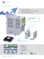
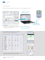
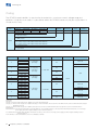
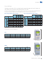
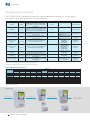
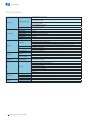
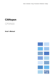
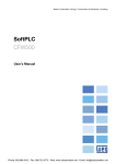
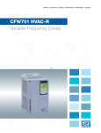
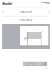
Motors | Automation | Energy | Transmission & Distribution | Coatings
CFW500 Machinery Drives
Variable Speed Drives
www.weg.net
One VSD, endless possibilities
Developed for fast commissioning, the CFW500 VSD is perfect for
machines. Extremely compact and cost-effective, it fulfills the needs of
machine manufacturers, integrated systems, panel installers and users for a
wide range of applications.
Compatible
Wide range of accessories
Characteristics
Flexible
Plug-in module
Application functions
Flash memory module
Robust
150% overload for one minute
SoftPLC
High overload capacity
Efficient
Streamlines operation and
performance
Functions to streamline
operation and
performance
Reliable
WEG quality
WEG quality
Integrable
Fieldbus networks
2
Frequency Inverter - CFW500
Communication networks
www.weg.net
Advantages
Benefits
The optional communication network and I/O modules
are fast and easily installed, allowing adapting the
standard VSD to each application.
Time saving, standardization and optimized costs
according to the needs.
In few seconds, it is possible to download the
programming from a CFW500 to others without powering
them up.
Fast, easy and reliable programming for manufacturers
that produce machines in large quantities.
Built-in PLC, enabling the VSD, motor and application to
work in an interactive way. It allows the user to
implement customized logics and applications.
It eliminates the need of an external PLC, reducing
costs, optimizing space and simplifying the system.
It withstands an overload of 150% for one minute every 6
minutes, on ambient temperature of 50 °C.
It does not require oversizing the VSD.
PID: process control.
Sleep: disables the VSD automatically.
Energy saving.
Flying start: allows driving the motor that is in free spinning,
accelerating it from the speed at which it was running.
It enables fast operating response of the machine and
prevents occasional mechanical breakdowns.
Ride through: keeps the VSD in
operation during voltage dips.
It prevents machine stoppage and downtime.
100% of the VSDs are tested with load at the factory
under rated conditions.
High reliability.
Protection against ground fault, short circuit, over
temperature and others.
It prevents damages to the inverter which can be caused
by adverse situations, normally external factors.
Thermal protection of IGBTs based on manufacturer curve.
All the electronic boards are conformally coated.
VSD lifespan is extended: protection against dust,
humidity, high temperatures and chemicals.
CANopen, DeviceNet, Profibus-DP and Modbus.
Full integration with process network.
Frequency Inverter - CFW500
3
www.weg.net
Easy Configuration
g
Fast commissioning
g
Innovative design, compact and uniform
g
Configurable cost x benefit
Plug-in Modules
Connections and interfaces at your
hands.
Fan
Simple and fast removal.
With plug-in module
CFW500-IOS
4
5
1
4
2
Frequency Inverter - CFW500
3
1 - Power terminals
2 - Access to DC link
3 - Motor terminals
4 - Control terminals (I/Os)
5 - RS485 port
www.weg.net
Applications
Centrifugal pumps
Process dosing pumps
g Fans / exhausters
g Stirrers / mixer
g Compressors
Conveyor belts
Roller tables
g Granulators / palletizers
g Dryers
g Rotary filters
g
g
g
g
Frequency Inverter - CFW500
5
www.weg.net
Human-Machine Interface
g
View
of three parameters at the same time,
selected by the user
CFW500 status
Secondary display
Parameter groups
Unit of measurement
(it refers to the value
of the main display)
Bar for
variable monitoring
Main display
Soft keys
Friendly Programming
JJ Oriented start-up: programming step by step
JJ Soft keys: fast access to the parameters
JJ Parameter group: it directs to the parameters of interest
Remote HMI
Solution for panel door or machine console.
CFW500-HMIR
IP54
RS485
Included in all plug-in
modules
CFW500-CCHMIRXM
X = up to 10 m
6
Frequency Inverter - CFW500
www.weg.net
Energy Efficiency
In the industry, the electric motors are responsible for
nearly 70% of all the electric energy consumption. By
using VSD, is possible to reduce consumption up to
40%.
Besides being efficient in the control of electric motors, they
reduce machine wear, save raw material, improve process quality
and increase productivity.
On WEG website, it is possible to calculate how much energy
can be saved by using the CFW500 VSD.
Ensure energy efficiency for your equipment and machines. Save
money and contribute to the conservation of the environment.
Frequency Inverter - CFW500
7
www.weg.net
SuperDrive G2
Software application for programming, command and monitoring of WEG VSD.
Friendly environment
USB connection
Trace Function
JJ On-line graphic monitoring of parameters/variables
JJ Possibility to export an image with the respective graph
according to the selected period
Free on www.weg.net
Edition and Monitoring of Parameters in List/Table
Parameter set storage in a computer file format.
Status Monitoring
Operation with HMI
On-line parameter edition
JJ
JJ
8
Transfer of parameters from the PC to the CFW500 and vice versa
Off-line edition of the parameters stored on the PC
Frequency Inverter - CFW500
www.weg.net
SoftPLC - Built-in on the Standard Product
It adds the functionalities of a PLC to the CFW500, allowing the creation of applications. The WLP
software and the SoftPLC functionality are a smart and simple way to make your CFW500, motor
and application work together.
Easy programming: Ladder
Speed reference
Trace Function
JJ On-line graphic monitoring of
parameters/variables
JJ Configurable up to six channels
Contacts and coils
Comparators and math
functions
Counters and
timers
PID
User block protected by
password
On-line Monitoring Parameters/Variables List
Enable/Disable I/Os
It simplifies and speeds up the validation of the
application
Parameter Edition
It allows to change the parameters values.
I/Os Monitoring
Frequency Inverter - CFW500
9
www.weg.net
Coding
The CFW500 code identifies its constructive characteristics, maximum current, voltage range and
optionals. Using the smart code, it is possible to select the CFW500 necessary for your application in a
simple and fast way.
Product and
series
CFW500
Model identification
Frame size
Rated current
No. of phases
Rated voltage
A
03P6
T
4
Braking ¹
Degree of
protection ¹
Conducted
emission level ¹
Hardware
version
Software
version
NB
20
C3
H00
---
Check table below
NB = without dynamic braking
DB = with dynamic braking
20 = IP20
N1 = NEMA1 enclosure
CFW500
Blank = with no RFI filter
C2 = According to category 2 of IEC 61800-3 standard, with internal RFI flter
C3 = According to category 3 of IEC 61800-3 standard, with internal RFI flter
H00 = without plug-in module
Blank = standard
Sx = special software
(1) To know what models have this options in the standard product the table below shall be checked.
Frame sizes
Output Current
Input
Power supply voltage
Braking
Degree of protection
Conducted emission level (2)
01P6 = 1.6 A
A
02P6 = 2.6 A
04P3 = 4.3 A
S = single-phase
power supply
Blank or C2
NB
07P0 = 7.0 A
Blank or C3
01P6 = 1.6 A
A
02P6 = 2.6 A
04P3 = 4.3 A
B
A
07P3 = 7.3 A
B = single-phase
or three-phase
power supply
NB
2 = 200... 240 V
DB
10P0 = 10 A
07P0 = 7.0 A
09P6 = 9.6 A
B
16P0 = 16 A
C
24P0 = 24 A
Blank
NB
T = three-phase
power supply
DB
DB
20 or N1
01P0 = 1.0 A
01P6 = 1.6 A
A
02P6 = 2.6 A
NB
Blank or C2
04P3 = 4.3 A
06P1 = 6.1 A
02P7 = 2.7 A
B
04P3 = 4.3 A
06P5 = 6.5 A
T = three-phase
power supply
Blank or C3
4 = 380...480 V
DB
10P0 = 10 A
C
14P0 = 14.0 A
16P0 = 16.0 A
Blank or C2
Blank or C3
DB
Blank or C3
(2) RFI filter
Categories:
Category C1: inverters with voltages below 1,000 V, for use in the First Environment.
Category C2: inverters with voltages below 1,000 V, with plugs or mobile installation, when used in the “First Environment”, must be installed and started-up by a
qualified professional.
Category C3: inverters with voltages below 1,000 V, developed for use in the Second Environment and not designed for use in the “First Environment”.
Environments:
First Environment: environments that include household installations, such as buildings directly connected, without intermediate transformer, to a low-voltage
power supply grid, which supplies buildings used for domestic purposes.
Second Environment: includes all the buildings other than those directly connected to a low-voltage power supply grid, which supplies buildings used for
domestic purposes.
For the RFI filters of external installations, refer to the CFW500 user manual.
10
Frequency Inverter - CFW500
www.weg.net
Drive Ratings
The correct way to select a VSD is matching its output current to the motor rated current. However, the
tables below present the expected motor power for each VSD model.
Use the motor power ratings below only as a guidance. Motor rated currents may vary with speed and manufacturer. IEC
motor powers are based on WEG 4-pole motors; NEMA motor powers are based on NEC table 430-150.
Motor Voltages Between 220 V and 230 V
1/3Ø
3Ø
200-240 V
1Ø
Model
CFW500 A 01P6 S2
CFW500 A 02P6 S2
CFW500 A 04P3 S2
CFW500 A 07P0 S2
CFW500 A 01P6 B2
CFW500 A 02P6 B2
CFW500 A 04P3 B2
CFW500 B 07P3 B2
CFW500 B 10P0 B2
CFW500 A 07P0 T2
CFW500 A 09P6 T2
CFW500 B 16P0 T2
CFW500 C 24P0 T2
A
1.6
2.6
4.3
7
1.6
2.6
4.3
7.3
10
7
9.6
16
24
IEC
NEMA
60 Hz
220 V
60 Hz
230 V
HP
0.25
0.5
1
2
0.25
0.5
1
2
3
2
3
5
7.5
HP
1
1
1.5
2
1
1
1.5
2
3
2
3
5
7.5
IEC
Rated current
Power
supply
Model
CFW500 A 01P0 T4
CFW500 A 01P6 T4
CFW500 A 02P6 T4
CFW500 A 04P3 T4
CFW500 A 06P1 T4
CFW500 B 02P6 T4
CFW500 B 04P3 T4
CFW500 B 06P5 T4
CFW500 B 10P0 T4
CFW500 C 14P0 T4
CFW500 C 16P0 T4
3Ø
Power
supply
IEC
50 Hz
220 V
230 V
kW
0.25
0.55
1.1
1.5
0.25
0.55
1.1
1.5
2.2
1.5
2.2
4
5.5
380-480 V
Rated current
Motor Voltages Between 380 V and 480 V
A
1
1.6
2.6
4.3
6.1
2.6
4.3
6.5
10
14
16
50 Hz
380 V
415 V
kW
0.25
0.75
1.1
1.5
3
1.1
1.5
3
4
7.5
7.5
NEMA
60 Hz
440 V
460 V
HP
0.5
0.75
1.5
3
4
1.5
3
4
7.5
10
12.5
60 Hz
460 V
HP
1
1
2
3
3
2
3
5
7.5
10
10
Dimensions and Weights
IP20
Frame
size
H
mm
W
mm
D
mm
Weight
Kg
A
189.1
75.2
149.5
0.8
B
199.1
100.2
160.1
1.2
C
210
135.2
165.1
2
H
D
W
NEMA1
Frame
size
H
mm
W
mm
D
mm
Weight
Kg
A
223
75.2
149.5
1.05
B
243.3
100.2
160.1
1.49
C
254.8
135.2
165.1
2.35
H
D
W
Frequency Inverter - CFW500
11
www.weg.net
Accessories and Optionals
The CFW500 VSD was developed to meet the hardware configurations required by a wide range of
applications. The table below presents the available options:
Option
Type (1)
Description
Used to reduce the disturbance conducted from the
CFW500 to the power supply, in the high frequency
band (>150 kHz), according to standards 61800-3
and EN 55011.
Used in high-inertia applications for the fast stop of
the motor by means of an external braking resistance.
Resistance not included. For the calculation of the
braking resistance, refer to the CFW500 user manual.
Used for the CFW500 VSD to have degree of
protection NEMA1 and/or when metallic conduits are
used for the cables.
Used to shield the power and control cables.
Important: for the version with RFI filter, this filter
comes with the product.
Optional item code (2)
Accessory model
Available
RFI filter
Optional
C2 o C3
-
Installed at the factory
Braking IGBT
Optional
DB
-
Installed at the factory
Degree of protection NEMA1
Optional or
accessory
Cable shield kit
Accessory
I/O expansion modules
(plug-in) (3)
Accessory
Used to configure the I/O points according to the
needs of the application/machine.
-
Communication module
(plug-in) (3)
Accessory
Used for the communication of the CFW500 with the
main networks of the market (Fieldbus).
Flash memory module
(plug-in) (3)
Accessory
Remote HMI
Accessory
Cables for remote HMI
Accessory
CFW500-KN1A (frame size A)
CFW500-KN1B (frame size B)
CFW500-KN1C (frame size C)
CFW500-KPCSA (frame size A)
CFW500-KPCSB (frame size B)
CFW500-KPCSC (frame size C)
CFW500-IOS
CFW500-IOD
CFW500-IOAD
CFW500-IOR
CFW500-CUSB (USB)
CFW500-CCAN
(CANopen /DeviceNet)
CFW500-CRS232
CFW500-CRS485
CFW500-CPDP (Profibus-DP)
N1
-
-
Used to download the programming of a CFW500 to
others without having to power them up.
Used to transfer the operation to the panel door or
machine console. Maximum distance of 10m. Degree
of protection IP54.
Used to interconnect the CFW500 to the remote HMI
(CFW500-HMIR).
Installed at the factory
or at the application
Installed at the
application
Installed at the
application
Installed at the
application
-
CFW500-MMF
Installed at the
application
-
CFW500-HMIR
Installed at the
application
-
CFW500-CCHMIRXM, where
cables with lengths (X) of 1, 2,
3, 5, 7,5 and 10 meters
Installed at the
application
(1) Optional = hardware resources added to the CFW500 in the manufacturing process
Accessory = hardware resource requested as a separated item.
(2) Request the product according to the code available on page 10.
Plug-in Modules Specification (3)
Plug-in module
CFW500-IOS
CFW500-IOD
CFW500-IOAD
CFW500-IOR
CFW500-CUSB
CFW500-CCAN
CFW500-CRS232
CFW500-CRS485
CFW500-CPDP
Inputs
Outputs
Digital
Analog
Analog
Digital relay
4
8
6
4
4
2
2
4
2
1
1
3
1
1
1
1
2
1
1
1
2
1
1
1
1
1
1
1
1
1
4
1
1
1
2
1
Functions
Digital
transistor
1
4
3
1
1
1
1
1
1
USB Port
1
-
CANopen/
DeviceNet
Fieldbus networks
Power supply
RS232
RS485
Profibus-DP
10 V
24 V
1
-
1
1
1
1
1
1
1
2
1
1
1
1
1
1
1
1
1
-
1
1
1
1
1
1
1
1
1
1
-
(3)All models of plug-in modules have at least one RS485 port. The CFW500-CRS485 plug-in module has two RS485 ports. The CFW500 allows installing one
plug-in module per unit.
Step by Step
1 - Remove cover
12
2 - Insert accessory
Frequency Inverter - CFW500
3 - Close cover
Simple!
www.weg.net
Block Diagram
1
DC+
DC2
1 = DC link connection
2 = Braking resistor connection
BR
Pre-load
Power
Supply
Rectifier
Motor
IGBT
RFI Filter
PE
DC Link
POWER
Feedbacks (**):
-Voltage
-Current
PE
CONTROL
Power supplies for electronics and for
interface between power and control
Operating Interface
(HMI)
CPU
32 bits
‘‘RISC’’
EEPROM
(memory)
Operating Interface
Remote HMI
CONTROL
CFW500-IOS PLUG-IN
MODULE (*)
RS485
Software WLP
SuperDrive
G2
Modbus
Interfaces
(RS232,
RS485
or USB)
Power Supply 10 V
Power Supply 24 V
Analog
Output (AO1)
Plug-in
Module
Digital
Output DO1 (RL1)
Digital Inputs
(DI1 to DI4)
Digital
Output DO2 (TR)
Analog Inputs
(AI1)
Accessory
Flash Memory
(CFW500-MMF)
(*) The number of inputs and outputs (analog and digital), as well as other resources, may vary according to the used plug-in module. For further information,
refer to the CFW500 user manual.
(**) Not available for frame size A.
Frequency Inverter - CFW500
13
www.weg.net
Technical Data
1-phase, 200-240 V ac ( +10%-15%)
0.25 to 2 HP (0.25 to 1.5 kW)
Power supply
Voltage and power range
1-phase/3-phase, 200-240 V ac ( +10%-15%)
0.25 to 3 HP (0.25 to 2.2 kW)
3-phase, 200-240 V ac ( +10%-15%)
2 to 7.5 HP (1.5 to 5.5 kW)
3-phase, 380-480 V ac ( +10%-15%)
0.5 to 12.5 HP (0.25 to 7.5 kW)
Motor connection
Supply frequency
50/60 Hz (48 Hz to 62 Hz)
Voltage
3-phase, 0-100% of supplied voltage
Output frequency
0 a 500 Hz
Displacement power factor
>0.97
Overload capacity
1.5 x In (drive) for 1 minute every 6 minutes
Switching frequency
Default 5 kHz (selectable 2.5 to 15 kHz)
Aceleration time
0.1 to 999s
Desaceleration time
0.1 to 999s
40 ºC - NEMA1
Temperature
Environment
50 ºC - IP20 without RFI filter
2% of current derating for each ºC above the specific operating temperature, limited to an increase of 10 ºC
Humidity
Altitude
Degree of protection
V/f control
Performance
Vector control (VVW)
Braking methods
40 ºC - IP20 side by side and/or with RFI flter
DC Current applied to motor
dynamic braking
5 % to 90 % non-condensing
Up to 1000 m - rated conditions
1000 m to 4000 m - 1 % of current derating for each 100 m above 1000 m of altitude
IP20 or NEMA1 (with kit NEMA1)
Speed regulation: 1 % of the rated speed (with slip compensation)
Speed variation range: 1:20
Speed regulation: 1 % of the rated speed
Speed variation range: 1:30
Available as standard for frame sizes B and C. For frame size A “DB” models has to be used. An extra resistor must be fitted
in for dynamic braking capability
Overcurrent/phase-phase short circuit in the output
Overcurrent/phase-ground short circuit in the output
Under/overvoltage
Safety
Protection
Overtemperature in the heatsink
Overload in the motor
Overload in the power module (IGBTs)
External alarm / fault
Setting error
Communication
Chokes (external as
accessory)
14
Modbus-RTU
All plug-in modules for RS485 and CFW500-CRS232 for RS232
Profbus-DP
Plug-in module CFW500-CPDP
DeviceNet
Plug-in module CFW500-CCAN
CANopen
Plug-in module CFW500-CCAN
AC input chokes
For reducing THD
AC output chokes
For longer motor cables
Frequency Inverter - CFW500
www.weg.net
Technical Data - Standards
Safety standards
Electromagnetic
Compatibility (EMC)
Standards
Mechanical construction
standards
UL 508C
Power conversion equipment.
UL 840
Insulation coordination including clearances and creepage distances for electrical equipment.
EN61800-5-1
Safety requirements electrical, thermal and energy.
EN 50178
Electronic equipment for use in power installations.
EN 60204-1
Safety of machinery. Electrical equipment of machines. Part 1: General requirements.
Note: For the machine to comply with this standard, the manufacturer of the machine is responsible for installing an
emergency stop device and equipment to disconnect the input power supply.
EN 60146 (IEC 146)
Semiconductor converters.
EN 61800-2
Adjustable speed electrical power drive systems - Part 2: General requirements - Rating specifcations for low voltage
adjustable frequency AC power drive systems.
EN 61800-3
Adjustable speed electrical power drive systems - Part 3: EMC product standard including specifc test methods.
EN 55011
Limits and methods of measurement of radio disturbance characteristics of industrial, scientifc and medical (ISM) radiofrequency equipment.
CISPR 11
Industrial, scientifc and medical (ISM) radio-frequency equipment - Electromagnetic disturbance characteristics - Limits
and methods of measurement.
EN 61000-4-2
Electromagnetic compatibility (EMC) - Part 4: Testing and measurement techniques - Section 2: Electrostatic discharge
immunity test.
EN 61000-4-3
Electromagnetic compatibility (EMC) - Part 4: Testing and measurement techniques - Section 3: Radiated, radio-frequency,
electromagnetic feld immunity test.
EN 61000-4-4
Electromagnetic compatibility (EMC) - Part 4: Testing and measurement techniques - Section 4: Electrical fast transient/
burst immunity test.
EN 61000-4-5
Electromagnetic compatibility (EMC) - Part 4: Testing and measurement techniques - Section 5: Surge immunity test.
EN 61000-4-6
Electromagnetic compatibility (EMC) - Part 4: Testing and measurement techniques - Section 6: Immunity to conducted
disturbances, induced by radio-frequency fields.
EN 60529
Degrees of protection provided by enclosures (IP code).
UL 50
Enclosures for electrical equipment.
Frequency Inverter - CFW500
15
ARGENTINA
WEG EQUIPAMIENTOS
ELECTRICOS
San Francisco - Cordoba
Phone: +54 3564 421 484
[email protected]
www.weg.net/ar
WEG PINTURAS - Pulverlux
Buenos Aires
Phone: +54 11 4299 8000
[email protected]
AUSTRALIA
WEG AUSTRALIA
Victoria
Phone: +61 3 9765 4600
[email protected]
www.weg.net/au
AUSTRIA
WATT DRIVE - WEG Group
Markt Piesting - Viena
Phone: +43 2633 404 0
[email protected]
www.wattdrive.com
BELGIUM
WEG BENELUX
Nivelles - Belgium
Phone: +32 67 88 84 20
[email protected]
www.weg.net/be
BRAZIL
WEG EQUIPAMENTOS ELÉTRICOS
Jaraguá do Sul - Santa Catarina
Phone: +55 47 3276-4002
[email protected]
www.weg.net/br
CHILE
WEG CHILE
Santiago
Phone: +56 2 784 8900
[email protected]
www.weg.net/cl
CHINA
WEG NANTONG
Nantong - Jiangsu
Phone: +86 0513 8598 9333
[email protected]
www.weg.net/cn
COLOMBIA
WEG COLOMBIA
Bogotá
Phone: +57 1 416 0166
[email protected]
www.weg.net/co
MEXICO
WEG MEXICO
Huehuetoca
Phone: +52 55 5321 4231
[email protected]
www.weg.net/mx
SINGAPORE
WEG SINGAPORE
Singapore
Phone: +65 68589081
[email protected]
www.weg.net/sg
FRANCE
WEG FRANCE
Saint Quentin Fallavier - Lyon
Phone: +33 4 74 99 11 35
[email protected]
www.weg.net/fr
VOLTRAN - WEG Group
Tizayuca - Hidalgo
Phone: +52 77 5350 9354
www.voltran.com.mx
SCANDINAVIA
WEG SCANDINAVIA
Kungsbacka - Sweden
Phone: +46 300 73 400
[email protected]
www.weg.net/se
GERMANY
WEG GERMANY
Kerpen - North Rhine Westphalia
Phone: +49 2237 9291 0
[email protected]
www.weg.net/de
GHANA
ZEST ELECTRIC GHANA
WEG Group
Accra
Phone: +233 30 27 664 90
[email protected]
www.zestghana.com.gh
INDIA
WEG ELECTRIC INDIA
Bangalore - Karnataka
Phone: +91 80 4128 2007
[email protected]
www.weg.net/in
WEG INDUSTRIES INDIA
Hosur - Tamil Nadu
Phone: +91 4344 301 501
[email protected]
www.weg.net/in
ITALY
WEG ITALIA
Cinisello Balsamo - Milano
Phone: +39 02 6129 3535
[email protected]
www.weg.net/it
JAPAN
WEG ELECTRIC MOTORS
JAPAN
Yokohama City - Kanagawa
Phone: +81 45 550 3030
[email protected]
www.weg.net/jp
NETHERLANDS
WEG NETHERLANDS
Oldenzaal - Overijssel
Phone: +31 541 571 080
[email protected]
www.weg.net/nl
PERU
WEG PERU
Lima
Phone:+51 1 472 3204
[email protected]
www.weg.net/pe
PORTUGAL
WEG EURO
Maia - Porto
Phone: +351 22 9477705
[email protected]
www.weg.net/pt
RUSSIA and CIS
WEG ELECTRIC CIS
Saint Petersburg
Phone: +7 812 363 2172
[email protected]
www.weg.net/ru
SOUTH AFRICA
ZEST ELECTRIC MOTORS
WEG Group
Johannesburg
Phone: +27 11 723 6000
[email protected]
www.zest.co.za
UK
WEG ELECTRIC MOTORS U.K.
Redditch - Worcestershire
Phone: +44 1527 513 800
[email protected]
www.weg.net/uk
UNITED ARAB EMIRATES
WEG MIDDLE EAST
Dubai
Phone: +971 4 813 0800
[email protected]
www.weg.net/ae
USA
WEG ELECTRIC
Duluth - Georgia
Phone: +1 678 249 2000
[email protected]
www.weg.net/us
ELECTRIC MACHINERY
WEG Group
Minneapolis - Minnesota
Phone: +1 612 378 8000
www.electricmachinery.com
VENEZUELA
WEG INDUSTRIAS VENEZUELA
Valencia - Carabobo
Phone: +58 241 821 0582
[email protected]
www.weg.net/ve
SPAIN
WEG IBERIA
Madrid
Phone: +34 91 655 30 08
[email protected]
www.weg.net/es
For those countries where there is not a WEG own operation, find our local distributor at www.weg.net.
Grupo WEG - Automation Business Unit
Jaraguá do Sul - SC - Brazil
Phone: +55 47 3276 4000
[email protected]
www.weg.net
Cod: 50036259 | Rev: 00 | Date (m/y): 06/2013
The values shown are subject to change without prior notice.
WEG Worldwide Operations