1
MXDE3
DeviceNet & Ethernet
Communications
Module
User’s Manual
890041-01-02
ADVANCED CONTROLS & DRIVES
MXDE3 DeviceNet and Ethernet Communications Module
ADVANCED CONTROLS & DRIVES
2
Table of Contents
1 - Introduction
Technical Support . . . . . . . . . . . . . . . . . . . . . . . . . . . . . . . . . . . . . . . . . . . . . . . . . . . . . . . . . 9
Start-Up Services . . . . . . . . . . . . . . . . . . . . . . . . . . . . . . . . . . . . . . . . . . . . . . . . . . . . . . . . . . 9
Documentation . . . . . . . . . . . . . . . . . . . . . . . . . . . . . . . . . . . . . . . . . . . . . . . . . . . . . . . . . . . . 9
On-Line Documentation . . . . . . . . . . . . . . . . . . . . . . . . . . . . . . . . . . . . . . . . . . . . . . . . . . . . . 9
Replacement Parts . . . . . . . . . . . . . . . . . . . . . . . . . . . . . . . . . . . . . . . . . . . . . . . . . . . . . . . . . 9
Publication History . . . . . . . . . . . . . . . . . . . . . . . . . . . . . . . . . . . . . . . . . . . . . . . . . . . . . . . . . 9
Warranty . . . . . . . . . . . . . . . . . . . . . . . . . . . . . . . . . . . . . . . . . . . . . . . . . . . . . . . . . . . . . . . . . 9
Contacting Benshaw . . . . . . . . . . . . . . . . . . . . . . . . . . . . . . . . . . . . . . . . . . . . . . . . . . . . . . 10
Overview . . . . . . . . . . . . . . . . . . . . . . . . . . . . . . . . . . . . . . . . . . . . . . . . . . . . . . . . . . . . . . . 11
MXDE3 Communications Module . . . . . . . . . . . . . . . . . . . . . . . . . . . . . . . . . . . . . . . . . . . . . . . 11
Technical Specifications . . . . . . . . . . . . . . . . . . . . . . . . . . . . . . . . . . . . . . . . . . . . . . . . . . . . . . 11
MXDE3 Part Numbers . . . . . . . . . . . . . . . . . . . . . . . . . . . . . . . . . . . . . . . . . . . . . . . . . . . . . . . . 11
2 - Installation
DeviceNet Considerations . . . . . . . . . . . . . . . . . . . . . . . . . . . . . . . . . . . . . . . . . . . . . . . . . .
DeviceNet Cable Length Limits . . . . . . . . . . . . . . . . . . . . . . . . . . . . . . . . . . . . . . . . . . . . . .
Table 1: DeviceNet Cable Limits . . . . . . . . . . . . . . . . . . . . . . . . . . . . . . . . . . . . . . . . . . . . . . . .
LEDs and Connectors . . . . . . . . . . . . . . . . . . . . . . . . . . . . . . . . . . . . . . . . . . . . . . . . . . . . .
DeviceNet Connector . . . . . . . . . . . . . . . . . . . . . . . . . . . . . . . . . . . . . . . . . . . . . . . . . . . . . .
Table 2: DeviceNet Connector Description (PORT0) . . . . . . . . . . . . . . . . . . . . . . . . . . . . . . . .
Starter Connector . . . . . . . . . . . . . . . . . . . . . . . . . . . . . . . . . . . . . . . . . . . . . . . . . . . . . . . . .
Table 3: DB-9 Connector Description (PORT1) . . . . . . . . . . . . . . . . . . . . . . . . . . . . . . . . . . . . .
Ethernet (RJ45) Connector . . . . . . . . . . . . . . . . . . . . . . . . . . . . . . . . . . . . . . . . . . . . . . . . .
Power Connector . . . . . . . . . . . . . . . . . . . . . . . . . . . . . . . . . . . . . . . . . . . . . . . . . . . . . . . . .
Activity LEDs . . . . . . . . . . . . . . . . . . . . . . . . . . . . . . . . . . . . . . . . . . . . . . . . . . . . . . . . . . . .
Wiring Examples . . . . . . . . . . . . . . . . . . . . . . . . . . . . . . . . . . . . . . . . . . . . . . . . . . . . . . . . .
Serial . . . . . . . . . . . . . . . . . . . . . . . . . . . . . . . . . . . . . . . . . . . . . . . . . . . . . . . . . . . . . . . . . . . . .
DeviceNet . . . . . . . . . . . . . . . . . . . . . . . . . . . . . . . . . . . . . . . . . . . . . . . . . . . . . . . . . . . . . . . . .
Quickstart - Web Page Based Setup . . . . . . . . . . . . . . . . . . . . . . . . . . . . . . . . . . . . . . . . . .
Web Page . . . . . . . . . . . . . . . . . . . . . . . . . . . . . . . . . . . . . . . . . . . . . . . . . . . . . . . . . . . . . . . . .
DeviceNet Configuration . . . . . . . . . . . . . . . . . . . . . . . . . . . . . . . . . . . . . . . . . . . . . . . . . . . . . .
Ethernet Configuration . . . . . . . . . . . . . . . . . . . . . . . . . . . . . . . . . . . . . . . . . . . . . . . . . . . . . . . .
Diagnostics . . . . . . . . . . . . . . . . . . . . . . . . . . . . . . . . . . . . . . . . . . . . . . . . . . . . . . . . . . . . . . . .
13
13
13
14
14
14
14
14
15
15
16
17
17
17
18
18
19
20
21
3 - CIP Device Profile
Data Types . . . . . . . . . . . . . . . . . . . . . . . . . . . . . . . . . . . . . . . . . . . . . . . . . . . . . . . . . . . . . .
Table 4: Data Types Used in the Object Model . . . . . . . . . . . . . . . . . . . . . . . . . . . . . . . . . . . . .
Identity Object (0x01 - 1 Instance) . . . . . . . . . . . . . . . . . . . . . . . . . . . . . . . . . . . . . . . . . . . .
Table 5: Identity Object Class Attributes (0x01 - Instance 0) . . . . . . . . . . . . . . . . . . . . . . . . . . .
Table 6: Identity Object Instance Attributes (0x01 - Instance 1) . . . . . . . . . . . . . . . . . . . . . . . .
Table 7: Identity Object Status Values . . . . . . . . . . . . . . . . . . . . . . . . . . . . . . . . . . . . . . . . . . . .
Table 8: Identity Object Extended Device Status Values . . . . . . . . . . . . . . . . . . . . . . . . . . . . .
Table 9: Identity Object Common Services . . . . . . . . . . . . . . . . . . . . . . . . . . . . . . . . . . . . . . . .
Message Router Object (0x02 - 1 Instance) . . . . . . . . . . . . . . . . . . . . . . . . . . . . . . . . . . . . .
23
23
24
24
24
24
25
25
26
3
MXDE3 DeviceNet and Ethernet Communications Module
DeviceNet Object (0x03 - 1 Instance) . . . . . . . . . . . . . . . . . . . . . . . . . . . . . . . . . . . . . . . . . 27
Table 10: DeviceNet Object Class Attributes (0x03 - Instance 0) . . . . . . . . . . . . . . . . . . . . . . . . 27
Table 11: DeviceNet Object Instance Attributes (0x03 - Instance 1) . . . . . . . . . . . . . . . . . . . . . 27
Table 12: DeviceNet Object Common Services . . . . . . . . . . . . . . . . . . . . . . . . . . . . . . . . . . . . . 27
Input Assembly Object (0x04 - 25 Instances) . . . . . . . . . . . . . . . . . . . . . . . . . . . . . . . . . . . . 28
Table 13: Assembly Object Class Attributes (0x04 - Instance 0) . . . . . . . . . . . . . . . . . . . . . . . . 28
Table 14: Assembly Object Input Instance 50 (0x32) - Basic Overload Input . . . . . . . . . . . . . . . 28
Table 15: Assembly Object Input Instance 51 (0x33) - Extended Overload Input . . . . . . . . . . . 28
Table 16: Assembly Object Input Instance 52 (0x34) - Basic Motor Starter Input . . . . . . . . . . . 28
Table 17: Assembly Object Input Instance 53 (0x35) - Extended Motor Starter 1 Input . . . . . . . 28
Table 18: Assembly Object Input Instance 60 (0x3C) - Basic Softstart Input . . . . . . . . . . . . . . . 28
Table 19: Assembly Object Input Instance 61 (0x3D) - Extended Softstart Input . . . . . . . . . . . . 29
Table 20: Assembly Object Input Instance 150 (0x96) - Input Status . . . . . . . . . . . . . . . . . . . . . 29
Table 21: Assembly Object Input Instance 151 (0x97) - Input Currents . . . . . . . . . . . . . . . . . . . 29
Table 22: Assembly Object Input Instance 152 (0x98) - Input Currents & Voltages . . . . . . . . . . 30
Table 23: Assembly Object Input Instance 153 (0x99) - Input Current/Voltage Averages . . . . . 30
Table 24: Assembly Object Input Instance 154 (0x9A) - Input Alarms and Lockouts . . . . . . . . . 31
Table 25: Assembly Object Input Instance 155 (0x9B) - Input Protection . . . . . . . . . . . . . . . . . 31
Table 26: Assembly Object Input Instance 156 (0x9C) - Input Power . . . . . . . . . . . . . . . . . . . . 32
Table 27: Assembly Object Input Instance 158 (0x9E) - Input Statistics . . . . . . . . . . . . . . . . . . 32
Table 28: Assembly Object Input Instance 159 (0x9F) - Input Misc . . . . . . . . . . . . . . . . . . . . . . 33
Table 29: Assembly Object Input Data Mapping . . . . . . . . . . . . . . . . . . . . . . . . . . . . . . . . . . . . . 33
Output Assembly Object 33 (0x04 - 4 Instances) . . . . . . . . . . . . . . . . . . . . . . . . . . . . . . . . . 37
Table 30: Assembly Object Output Instance 1 (0x01) - Basic Contactor Output . . . . . . . . . . . . 37
Table 31: Assembly Object Output Instance Attribute 2 (0x02) - Basic Overload Output . . . . . . 37
Table 32: Assembly Object Output Instance Attribute 3 (0x03) - Basic Motor Starter Output . . 37
Table 33: Assembly Object Output Instance Attribute 100 (0x64) - Starter Control . . . . . . . . . . 37
Table 34: Assembly Object Output Data Mapping . . . . . . . . . . . . . . . . . . . . . . . . . . . . . . . . . . . 38
Heartbeat and Configuration Instances . . . . . . . . . . . . . . . . . . . . . . . . . . . . . . . . . . . . . . . . . 39
Table 35: Assembly Object - Common Services . . . . . . . . . . . . . . . . . . . . . . . . . . . . . . . . . . . . 39
Connection Object (0x05 - 2 Instances) . . . . . . . . . . . . . . . . . . . . . . . . . . . . . . . . . . . . . . . . 40
Table 36: Connection Object Class Attributes (0x05 - Instance 0) . . . . . . . . . . . . . . . . . . . . . . . 40
Table 37: Connection Object Instance Attributes (0x05 - Instance 1-2) Explicit, Polled I/O . . . . 40
Table 38: Connection Object - Common Services . . . . . . . . . . . . . . . . . . . . . . . . . . . . . . . . . . . 40
Connection Manager Object (0x06 - Ethernet/IP) . . . . . . . . . . . . . . . . . . . . . . . . . . . . . . . . . 41
Discrete Input Object (0x08 - 9 Instances) . . . . . . . . . . . . . . . . . . . . . . . . . . . . . . . . . . . . . . 42
Table 39: Discrete Input Object Class Attributes (0x08 - Instance 0) . . . . . . . . . . . . . . . . . . . . . 42
Table 40: Discrete Input Object Class Attributes (0x08 - Instances 1 - 9) . . . . . . . . . . . . . . . . . 42
Table 41: Discrete Input Object - Common Services . . . . . . . . . . . . . . . . . . . . . . . . . . . . . . . . . 42
Discrete Output Point Object (0x09 - 6 Instances) . . . . . . . . . . . . . . . . . . . . . . . . . . . . . . . . 43
Table 42: Discrete Output Point Object Class Attributes (0x09 - Instance 0) . . . . . . . . . . . . . . . 43
Table 43: Discrete Output Point Object Class Attributes (0x09 - Instances 1 - 6) . . . . . . . . . . . 43
Table 44: Discrete Output Point Object - Common Services . . . . . . . . . . . . . . . . . . . . . . . . . . . 43
Motor Data Object (0x28 - 1 Instance) . . . . . . . . . . . . . . . . . . . . . . . . . . . . . . . . . . . . . . . . . 44
Table 45: Motor Data Object Class Attributes (0x28 - Instance 0) . . . . . . . . . . . . . . . . . . . . . . . 44
Table 46: Motor Data Object Class Instance Attributes (Instance 1) . . . . . . . . . . . . . . . . . . . . . 44
Table 47: Motor Data Object - Common Services . . . . . . . . . . . . . . . . . . . . . . . . . . . . . . . . . . . 44
Control Supervisor Object (0x29 - 1 Instance) . . . . . . . . . . . . . . . . . . . . . . . . . . . . . . . . . . . 45
Table 48: Control Supervisor Object Class Attributes (0x29 - Instance 0) . . . . . . . . . . . . . . . . . 45
Table 49: Control Supervisor Object Class Instance Attributes (Instance 1) . . . . . . . . . . . . . . . 45
4
Table 50: Control Supervisor Object - Common Services . . . . . . . . . . . . . . . . . . . . . . . . . . . . .
Overload Object (0x2C - 1 Instance) . . . . . . . . . . . . . . . . . . . . . . . . . . . . . . . . . . . . . . . . . .
Table 51: Overload Object Class Attributes (0x2C - Instance 0) . . . . . . . . . . . . . . . . . . . . . . . .
Table 52: Overload Object Class Instance Attributes (Instance 1) . . . . . . . . . . . . . . . . . . . . . .
Table 53: Overload Object - Common Services . . . . . . . . . . . . . . . . . . . . . . . . . . . . . . . . . . . .
Softstart Object (0x2D - 1 Instance) . . . . . . . . . . . . . . . . . . . . . . . . . . . . . . . . . . . . . . . . . . .
Table 54: Softstart Object Class Attributes (0x2D - Instance 0) . . . . . . . . . . . . . . . . . . . . . . . .
Table 55: Softstart Object Class Instance Attributes (Instance 1) . . . . . . . . . . . . . . . . . . . . . . .
Table 56: Softstart Object - Common Services . . . . . . . . . . . . . . . . . . . . . . . . . . . . . . . . . . . . .
TCP Object - Ethernet I/P (0xF5 - 1 Instance) . . . . . . . . . . . . . . . . . . . . . . . . . . . . . . . . . . .
Table 57: TCP Object Class Attributes (0xF5 - Instance 0) . . . . . . . . . . . . . . . . . . . . . . . . . . . .
Table 58: TCP Object Class Instance Attributes (Instance 1) . . . . . . . . . . . . . . . . . . . . . . . . . .
Table 59: TCP Object - Common Services . . . . . . . . . . . . . . . . . . . . . . . . . . . . . . . . . . . . . . . .
Ethernet Link Object - Ethernet I/P (0xF6 - 1 Instance) . . . . . . . . . . . . . . . . . . . . . . . . . . . .
Table 60: Ethernet Link Object Class Attributes (0xF6 - Instance 0) . . . . . . . . . . . . . . . . . . . . .
Table 61: Ethernet Link Object Class Instance Attributes (Instance 1) . . . . . . . . . . . . . . . . . . .
Table 62: Ethernet Link Object - Common Services . . . . . . . . . . . . . . . . . . . . . . . . . . . . . . . . .
Modbus/Serial Object (0x65 - 1 Instance) . . . . . . . . . . . . . . . . . . . . . . . . . . . . . . . . . . . . . .
Table 63: Ethernet Link Object Class Attributes (0x65 - Instance 0) . . . . . . . . . . . . . . . . . . . . .
Table 64: Modbus/Serial Object Class Instance Attributes (Instance 1) . . . . . . . . . . . . . . . . . .
Table 65: Modbus/Serial Object - Common Services . . . . . . . . . . . . . . . . . . . . . . . . . . . . . . . .
Real Time Data Object - MX3 Only (0x66 - 1 Instance) . . . . . . . . . . . . . . . . . . . . . . . . . . . .
Table 66: Real TIme Data Object Class Attributes (0x66 - Instance 0) . . . . . . . . . . . . . . . . . . .
Table 67: Real TIme Data Object Class Instance Attributes (Instance 1) . . . . . . . . . . . . . . . . .
Table 68: Real TIme Data Object - Common Services . . . . . . . . . . . . . . . . . . . . . . . . . . . . . . .
Parameters Object - MX3 Only (0x67 - 1 Instance) . . . . . . . . . . . . . . . . . . . . . . . . . . . . . . .
Table 69: Parameter Object Class Attributes (0x67 - Instance 0) . . . . . . . . . . . . . . . . . . . . . . .
Table 70: Parameter Object Instance Attributes (Instance 1) - Read and Writeable . . . . . . . . .
Table 71: Parameter Object - Common Services . . . . . . . . . . . . . . . . . . . . . . . . . . . . . . . . . . .
Event Log Object - MX3 Only (0x68 - 99 Instances) . . . . . . . . . . . . . . . . . . . . . . . . . . . . . .
Table 72: Event Log Object Class Attributes (0x68 - Instance 0) . . . . . . . . . . . . . . . . . . . . . . .
Table 73: Event Log Object Instance Attributes (Instances 1-99) . . . . . . . . . . . . . . . . . . . . . . .
Table 74: Event Log Object - Common Services . . . . . . . . . . . . . . . . . . . . . . . . . . . . . . . . . . . .
Table 75: Event Log Object - Event Codes . . . . . . . . . . . . . . . . . . . . . . . . . . . . . . . . . . . . . . . .
Table 76: Event Log Object - System States Table . . . . . . . . . . . . . . . . . . . . . . . . . . . . . . . . . .
Status and Control Object (0x69 - 1 Instance) . . . . . . . . . . . . . . . . . . . . . . . . . . . . . . . . . . .
Table 77: Status and Control Object Class Attributes (0x69 - Instance 0) . . . . . . . . . . . . . . . .
Table 78: Status and Control Object Instance Attributes (Instance 1) . . . . . . . . . . . . . . . . . . . .
Table 79: Status and Control Object - Common Services . . . . . . . . . . . . . . . . . . . . . . . . . . . . .
Configuration Object (0x6A - 1 Instance) . . . . . . . . . . . . . . . . . . . . . . . . . . . . . . . . . . . . . . .
Table 80: Configuration Object Class Attributes (0x6A - Instance 0) . . . . . . . . . . . . . . . . . . . .
Table 81: Configuration Object Instance Attributes (Instance 1) . . . . . . . . . . . . . . . . . . . . . . . .
Table 82: Configuration Object - Common Services . . . . . . . . . . . . . . . . . . . . . . . . . . . . . . . . .
Fault Log Object (0x6B - 9 Instances) . . . . . . . . . . . . . . . . . . . . . . . . . . . . . . . . . . . . . . . . .
Table 83: Fault Log Object Class Attributes (0x6B - Instance 0) . . . . . . . . . . . . . . . . . . . . . . . .
Table 84: Fault Log Object Instance Attributes (Instances 1-9) . . . . . . . . . . . . . . . . . . . . . . . . .
Table 85: Fault Log Object - Fault Codes . . . . . . . . . . . . . . . . . . . . . . . . . . . . . . . . . . . . . . . . .
Table 86: System State Code Tables . . . . . . . . . . . . . . . . . . . . . . . . . . . . . . . . . . . . . . . . . . . .
Table 87: Fault Log Object - Common Services . . . . . . . . . . . . . . . . . . . . . . . . . . . . . . . . . . . .
45
46
46
46
46
47
47
47
47
48
48
48
48
49
49
49
49
50
50
50
50
51
51
51
52
53
53
53
58
59
59
59
59
59
61
62
62
62
65
66
66
66
78
79
79
79
79
81
82
5
MXDE3 DeviceNet and Ethernet Communications Module
DeviceNet Example . . . . . . . . . . . . . . . . . . . . . . . . . . . . . . . . . . . . . . . . . . . . . . . . . . . . . . . . 83
Purpose . . . . . . . . . . . . . . . . . . . . . . . . . . . . . . . . . . . . . . . . . . . . . . . . . . . . . . . . . . . . . . . . . . . 83
Hardware setup . . . . . . . . . . . . . . . . . . . . . . . . . . . . . . . . . . . . . . . . . . . . . . . . . . . . . . . . . . . . . . 83
Customizing the Communications Module . . . . . . . . . . . . . . . . . . . . . . . . . . . . . . . . . . . . . . . . . 84
RSNetWorx for DeviceNet . . . . . . . . . . . . . . . . . . . . . . . . . . . . . . . . . . . . . . . . . . . . . . . . . . . . . 84
4 - PCCC
PCCC Mapping . . . . . . . . . . . . . . . . . . . . . . . . . . . . . . . . . . . . . . . . . . . . . . . . . . . . . . . . . . . 91
Table 88: PCCC Mapping Table . . . . . . . . . . . . . . . . . . . . . . . . . . . . . . . . . . . . . . . . . . . . . . . . . 91
PCCC Example 88
PCCC . . . . . . . . . . . . . . . . . . . . . . . . . . . . . . . . . . . . . . . . . . . . . . . . . . . . . . . . . . . . . . . . . . . . . 92
Purpose . . . . . . . . . . . . . . . . . . . . . . . . . . . . . . . . . . . . . . . . . . . . . . . . . . . . . . . . . . . . . . . . . . . 92
RSLogix 500: Rung 0 . . . . . . . . . . . . . . . . . . . . . . . . . . . . . . . . . . . . . . . . . . . . . . . . . . . . . . . . . 93
Setup Screen (General): Rung 0 . . . . . . . . . . . . . . . . . . . . . . . . . . . . . . . . . . . . . . . . . . . . . . . . 93
Setup Screen (MultiHop): Rung 0 . . . . . . . . . . . . . . . . . . . . . . . . . . . . . . . . . . . . . . . . . . . . . . . . 94
5 - Modbus-TCP 91
Modbus-TCP Mapping . . . . . . . . . . . . . . . . . . . . . . . . . . . . . . . . . . . . . . . . . . . . . . . . . . . . . 95
Table 89: Modbus - TCP Mapping . . . . . . . . . . . . . . . . . . . . . . . . . . . . . . . . . . . . . . . . . . . . . . . 95
The Modbus-TCP Protocol . . . . . . . . . . . . . . . . . . . . . . . . . . . . . . . . . . . . . . . . . . . . . . . . . . 96
Modbus-TCP Example . . . . . . . . . . . . . . . . . . . . . . . . . . . . . . . . . . . . . . . . . . . . . . . . . . . . . 97
Purpose . . . . . . . . . . . . . . . . . . . . . . . . . . . . . . . . . . . . . . . . . . . . . . . . . . . . . . . . . . . . . . . . . . . 97
Assigning an IP Address . . . . . . . . . . . . . . . . . . . . . . . . . . . . . . . . . . . . . . . . . . . . . . . . . . . . . . . 97
Constructing a Read Message . . . . . . . . . . . . . . . . . . . . . . . . . . . . . . . . . . . . . . . . . . . . . . . . . . 98
6 - Troubleshooting
Communications Troubleshooting . . . . . . . . . . . . . . . . . . . . . . . . . . . . . . . . . . . . . . . . . . . . 101
Table 90: Communications Troubleshooting . . . . . . . . . . . . . . . . . . . . . . . . . . . . . . . . . . . . . . 101
General Troubleshooting . . . . . . . . . . . . . . . . . . . . . . . . . . . . . . . . . . . . . . . . . . . . . . . . . . . 101
Status LEDs . . . . . . . . . . . . . . . . . . . . . . . . . . . . . . . . . . . . . . . . . . . . . . . . . . . . . . . . . . . . . . . 101
EtherNet IP (LED1) . . . . . . . . . . . . . . . . . . . . . . . . . . . . . . . . . . . . . . . . . . . . . . . . . . . . . . . . . . 102
Table 91: LED 1 (Ethernet IP) Codes . . . . . . . . . . . . . . . . . . . . . . . . . . . . . . . . . . . . . . . . . . 102
DeviceNet (LED2) . . . . . . . . . . . . . . . . . . . . . . . . . . . . . . . . . . . . . . . . . . . . . . . . . . . . . . . . . . . 102
Table 92: LED 2 (DeviceNet) Codes . . . . . . . . . . . . . . . . . . . . . . . . . . . . . . . . . . . . . . . . . . . 102
Advanced DeviceNet Troubleshooting . . . . . . . . . . . . . . . . . . . . . . . . . . . . . . . . . . . . . . . . 103
Network Voltage Requirements (V+ to V-) . . . . . . . . . . . . . . . . . . . . . . . . . . . . . . . . . . . . . . . . 103
Check Signal Voltage Levels . . . . . . . . . . . . . . . . . . . . . . . . . . . . . . . . . . . . . . . . . . . . . . . . . . 103
Table 93: Signal Voltages . . . . . . . . . . . . . . . . . . . . . . . . . . . . . . . . . . . . . . . . . . . . . . . . . . . 103
Common Mode Voltage Test for Network Power . . . . . . . . . . . . . . . . . . . . . . . . . . . . . . . . . . . 103
Test for Termination Resistors . . . . . . . . . . . . . . . . . . . . . . . . . . . . . . . . . . . . . . . . . . . . . . . . . 103
Check for Noise . . . . . . . . . . . . . . . . . . . . . . . . . . . . . . . . . . . . . . . . . . . . . . . . . . . . . . . . . . . . 103
Appendix A - Modbus Registers 101
Starter Status and Control Common to the MX2 and MX3 . . . . . . . . . . . . . . . . . . . . . . . . . 105
Table 94: Modbus Registers - Starter Status & Control . . . . . . . . . . . . . . . . . . . . . . . . . . . . . . 105
Table 95: Starter Control Register . . . . . . . . . . . . . . . . . . . . . . . . . . . . . . . . . . . . . . . . . . . . . . 107
6
Starter Status and Control Unique to the MX3 . . . . . . . . . . . . . . . . . . . . . . . . . . . . . . . . . .
Table 96: Starter Status and Control (Unique to the MX3) . . . . . . . . . . . . . . . . . . . . . . . . . . .
Date/Time Registers . . . . . . . . . . . . . . . . . . . . . . . . . . . . . . . . . . . . . . . . . . . . . . . . . . . . .
Parameters Common to the MX2 and MX3 . . . . . . . . . . . . . . . . . . . . . . . . . . . . . . . . . . . .
Table 97: Parameters Common to MX2 and MX3 . . . . . . . . . . . . . . . . . . . . . . . . . . . . . . . . . .
Misc Command . . . . . . . . . . . . . . . . . . . . . . . . . . . . . . . . . . . . . . . . . . . . . . . . . . . . . . . . .
Parameters Unique to the MX3 . . . . . . . . . . . . . . . . . . . . . . . . . . . . . . . . . . . . . . . . . . . . .
Table 98: Unique MX3 Parameters . . . . . . . . . . . . . . . . . . . . . . . . . . . . . . . . . . . . . . . . . . . . .
Fault Log and Data . . . . . . . . . . . . . . . . . . . . . . . . . . . . . . . . . . . . . . . . . . . . . . . . . . . . . . .
Fault Codes . . . . . . . . . . . . . . . . . . . . . . . . . . . . . . . . . . . . . . . . . . . . . . . . . . . . . . . . . . . .
Table 99: Fault Codes . . . . . . . . . . . . . . . . . . . . . . . . . . . . . . . . . . . . . . . . . . . . . . . . . . . . . . .
System States . . . . . . . . . . . . . . . . . . . . . . . . . . . . . . . . . . . . . . . . . . . . . . . . . . . . . . . . . .
Table 100: System States . . . . . . . . . . . . . . . . . . . . . . . . . . . . . . . . . . . . . . . . . . . . . . . . . . . .
L1 Currents . . . . . . . . . . . . . . . . . . . . . . . . . . . . . . . . . . . . . . . . . . . . . . . . . . . . . . . . . . . .
L2 Currents . . . . . . . . . . . . . . . . . . . . . . . . . . . . . . . . . . . . . . . . . . . . . . . . . . . . . . . . . . . .
L3 Currents . . . . . . . . . . . . . . . . . . . . . . . . . . . . . . . . . . . . . . . . . . . . . . . . . . . . . . . . . . . .
L1-L2 Voltages . . . . . . . . . . . . . . . . . . . . . . . . . . . . . . . . . . . . . . . . . . . . . . . . . . . . . . . . . .
L2-L3 Voltages . . . . . . . . . . . . . . . . . . . . . . . . . . . . . . . . . . . . . . . . . . . . . . . . . . . . . . . . . .
L3-L1 Voltages . . . . . . . . . . . . . . . . . . . . . . . . . . . . . . . . . . . . . . . . . . . . . . . . . . . . . . . . . .
Kilowatts . . . . . . . . . . . . . . . . . . . . . . . . . . . . . . . . . . . . . . . . . . . . . . . . . . . . . . . . . . . . . . .
Line Periods . . . . . . . . . . . . . . . . . . . . . . . . . . . . . . . . . . . . . . . . . . . . . . . . . . . . . . . . . . . .
Run Time Hours . . . . . . . . . . . . . . . . . . . . . . . . . . . . . . . . . . . . . . . . . . . . . . . . . . . . . . . . .
Event Log (MX3 Only) . . . . . . . . . . . . . . . . . . . . . . . . . . . . . . . . . . . . . . . . . . . . . . . . . . . .
Event Codes . . . . . . . . . . . . . . . . . . . . . . . . . . . . . . . . . . . . . . . . . . . . . . . . . . . . . . . . . . . .
Table 101: Event Codes . . . . . . . . . . . . . . . . . . . . . . . . . . . . . . . . . . . . . . . . . . . . . . . . . . . . .
System States . . . . . . . . . . . . . . . . . . . . . . . . . . . . . . . . . . . . . . . . . . . . . . . . . . . . . . . . . .
Event Time and Date Stamp . . . . . . . . . . . . . . . . . . . . . . . . . . . . . . . . . . . . . . . . . . . . . . .
Table 102: Time and Date Stamp Registers . . . . . . . . . . . . . . . . . . . . . . . . . . . . . . . . . . . . . .
108
108
109
109
109
117
118
118
120
121
121
123
123
123
123
123
123
123
123
123
124
124
124
124
124
125
125
125
Appendix B - Reference Documents
Reference documents . . . . . . . . . . . . . . . . . . . . . . . . . . . . . . . . . . . . . . . . . . . . . . . . . . . . 127
7
MXDE3 DeviceNet and Ethernet Communications Module
ADVANCED CONTROLS & DRIVES
8
1 - Introduction
1 - Introduction
Technical Support
Technical Support personnel are available to answer questions and provide technical support over
the telephone. Refer to Page 10 for contact information.
Start-Up Services
Information about start-up services and fees are available by contacting Benshaw. Refer to Page
10 for contact information
Documentation
Benshaw can provide all customers with:
• Operation Manuals
• Wiring Diagrams
All drawings are produced in AutoCADTM and are available on CD / DVD or via e-mail by
contacting Benshaw Customer Service.
On-Line
Documentation
All MXDE3 documentation is available on-line at http://www.benshaw.cwfc.com
Replacement Parts
Spare and replacement parts can be purchased from Benshaw Technical Support.
Publication History
Refer to the inside back cover.
Warranty
Benshaw provides a standard 1 Year factory warranty of the MXDE3 Communication Module.
9
MXDE3 DeviceNet and Ethernet Communications Module
Contacting Benshaw
Information about Benshaw products and services is available by contacting Benshaw at one of
the following offices:
Benshaw Corporate Headquarters
Benshaw Canada
615 Alpha Drive
550 Bright Street East
Pittsburgh, PA 15116
Listowel, Ontario N4W 3W3
Phone: 412-968-0100
Phone: 519-291-5112
Tech Support: 1-800-203-2416
Tech Support: 1-877-291-5112
Fax: 412-968-5415
Fax: (519) 291-2595
Technical support for the MXDE3 Communication Module is available at no charge by contacting
Benshaw Customer Service at any of the above telephone numbers. A service technician is
available Monday through Friday from 8:00 a.m. to 5:00 p.m. EST.
NOTE: An on-call technician is available after normal business hours and on weekends by
calling Benshaw and following the recorded instructions.
To help assure prompt and accurate service, please have the following information available when
contacting Benshaw:
• Name of Company
• Telephone number where the caller can be contacted
• Fax number of caller
• Benshaw product name
• Benshaw model number
• Benshaw serial number
• Name of product distributor
• Approximate date of purchase
• A brief description of the application
10
1 - Introduction
Overview
MXDE3
Communications
Module
The Benshaw MXDE3 Communications Module is designed to make communicating with an MX2
or MX3 starter a simple and easy task. The MXDE3 requires only a few simple configuration
parameters to connect with a DeviceNet, EtherNet/IP, PCCC, or Modbus-TCP network.
Configuration parameters are easily accessed from the built in web server (refer to Section 4).
CAUTION: When using the MXDE3 on a DeviceNet, Modbus-TCP or EtherNet/IP
network, the serial timeout function of the MX2/MX3 must be enabled. Refer to the
Communications Timeout parameters in an MX2 or MX3 User Manual for details on
enabling the serial time-out function.
Technical
Specifications
Network Interface
RJ-45 10/100Base-T Ethernet port
Protocols Supported
EtherNet/IP
PCCC
Modbus-TCP
DeviceNet
LEDs
Five LEDs for device and communication status.
Refer to Section 6, Tables 91 and 92 for LED Diagnostic Codes
Physical Characteristics
Dimensions: 4.2”x 3.25”x 1”
Power Requirements
DC Input Voltage: 230mA @ 8V to 80mA @ 28V
Environmental
Operating Temperature: -40oC to +85oC
MXDE3 Part Numbers
DeviceNet Communications:
COM-100000-00
Ethernet Communications:
COM-100000-01
11
MXDE3 DeviceNet and Ethernet Communications Module
ADVANCED CONTROLS & DRIVES
12
2 - Installation
2 - Installation
DeviceNet
Considerations
DeviceNet can be configured in a variety of topologies. One example is outlined below.
There are physical specifications to consider when installing a DeviceNet network or adding a new
DeviceNet device. The table below outlines the maximum cable length for both trunk and drop
lines.
DeviceNet Cable
Length Limits
Table 1: DeviceNet Cable Limits
Comm Speed
125 Kbps
250 Kbps
500 Kbps
Thick Trunk Length
500m (1640ft)
250m (820ft)
100m (328ft)
Thin Trunk Length
100m (328 ft)
100m (328 ft)
100m (328 ft)
6m (20 ft)
6m (20 ft)
6m (20 ft)
156m (512ft)
78m (256ft)
39m (128ft)
Maximum Length of a Single Drop
Cumulative Length of All Drops
13
MXDE3 DeviceNet and Ethernet Communications Module
LEDs and Connectors
Port 0
(DeviceNet)
Port 1
(Starter)
DeviceNet Connector
Table 2: DeviceNet Connector Description (PORT0)
Starter Connector
PIN
CAN
1
V-
2
CAN-
3
SHIELD
4
CAN+
5
V+
The Starter Connector is used to connect the MXDE3 to a Benshaw starter. See Section 2, Page
17 for an example wiring diagram.
Table 3: DB-9 Connector Description (PORT1)
14
PIN
RS-485
2
A-
5
Common
7
B+
2 - Installation
Ethernet (RJ45)
Connector
The Ethernet Connector is located next to the Power LED on the back panel of the MXDE3.
Connect an RJ45 cable into the jack (shown below) on the MXDE3 communications module.
There are two LEDs associated with the Ethernet connection; Speed and Link. The Speed LED
indicates the current communication speed. If the Speed LED is off, the connection speed is 10
MB. If the Speed LED is illuminated, the connection speed is 100 MB. The Link LED indicates that
a valid link is established and there is activity on the connection.
NOTE: For Ethernet capabilities, the module must be powered by 8 to 28 VDC using the
supplied barrel connector.
Power Connector
The Power jack is located next to the Power LED (shown above). Insert the power connection from
the supplied 24VDC power supply into this jack. The Power LED should be illuminated whenever
power is applied.
CAUTION: DeviceNet should receive power from the DeviceNet network Port 0 only. Do
not supply power to the Power jack. For DeviceNet, the power jack is used for Ethernet
applications only.
15
MXDE3 DeviceNet and Ethernet Communications Module
Activity LEDs
16
There are two communication activity LEDs on the MXDE3 communications module, located on
the side opposite the DIN rail mounting hardware (pictured below). Both LEDs are two color, and
indicate various states of Ethernet and DeviceNet communications. LED1 indicates Ethernet
communication status, while LED2 indicates DeviceNet communications. For a complete list of
states, refer to Section 6, Troubleshooting.
2 - Installation
Wiring Examples
Serial
DeviceNet
17
MXDE3 DeviceNet and Ethernet Communications Module
Quickstart - Web Page Based Setup
Web Page
The Web Page Based Setup tool is designed to make both monitoring and basic configuration
intuitive and simple. Enter IP Address 192.168.1.200 (Default) into a connected web browser; the
Benshaw Soft Starter Controller web-page shown below will be displayed.
NOTE: The MXDE3 must be connected to the starter, and a computer to the MXDE3
ethernet port before accessing the web based configuration tool.
The Web Page Based Setup tool is divided into 4 sections: DeviceNet Configuration, Network
Configuration, Device Info, and Diagnostics.
18
2 - Installation
DeviceNet
Configuration
Selecting the Configure DeviceNet button on the Home Page will enable the DeviceNet
Configuration web-page below.
The DeviceNet Configuration screen enables access to a Controller Description, DeviceNet
Communication, and Assembly Configuration parameters.
19
MXDE3 DeviceNet and Ethernet Communications Module
To enter a description, click within the Description field and enter the new description. Specifying a
new MAC ID number is accomplished in the same manner. To select a different Baud Rate, click
on the drop down arrow next to the current baud rate, then select either 125, 250, or 500 kbps. To
select a different Input or Output Assembly, click on the drop down arrow next to the current
assembly and select one from the drop down list. Click Store Parameters to save the changes.
Ethernet
Configuration
Click the Edit button within the Network Settings box on the home page to access the Network
Setup web-page shown below.
From the Network Setup screen the IP Address, Subnet Mask, and Default Gateway can be
configured. Click within the first box of the parameter to be changed, erase the current value, then
enter the required value. After the first three digits are entered, the next box will automatically
highlight. Continue to enter new values to overwrite the current values, and each subsequent box
will highlight when the current box is full. Conversely, double-clicking on any box enables
overwriting of a current value. When changes are complete, click Store Parameters to save the
changes and return to the Main screen.
20
2 - Installation
Diagnostics
Clicking on the Diagnostics button at the bottom of the home page enables access to the
Diagnostics web page below.
Information on the Diagnostics page pertains only to the RS485 Modbus connection between the
MXDE3 and the starter: It does not pertain to the Modbus-TCP interface.
The MXDE3 must be connected to the starter. Use the web page shown above to ensure that
Enable is set to 1 and Timeout is set to 2 in the Modbus Timeout box.
In the Counters box, the current number of read/write successes, read/write timeouts and read/
write errors can be monitored. A communications timeout occurs if there is no response within the
timeout limit after a read or write is requested. On-screen data is not automatically updated, and
must be refreshed by pressing F5 on the PC keyboard. Clicking on the Clear Counters button at
the bottom of this screen will reset all counters to zero.
The current state of the Starter Control and Status Registers can be viewed in the Register Status
box. The Starter Control Register provides the current states of various digital inputs and relay
outputs. The Starter Status Register provides the current state of the starter. On-screen data is not
automatically updated, and must be refreshed by pressing F5 on the PC keyboard.
Clicking on the Return to Main Page button will return the display to the Main page.
21
MXDE3 DeviceNet and Ethernet Communications Module
22
3 - CIP Device Profile
3 - CIP Device Profile
The CIP (Common Interface Profile) is utilized by both DeviceNet and Ethernet/IP.
Data Types
The following data types are used in the Object model for the MXDE3 communications module.
Table 4: Data Types Used in the Object Model
Data Type
USINT
UINT
UDINT
INT
DINT
STRING
SHORT STRINGnn
Description
Unsigned Short Integer (8-bit)
Unsigned Integer (16-bit)
Unsigned Double Integer (32-bit)
Signed Integer (16-bit)
Single Double Integer (32-bit)
Character String (1 Byte per Character)
Character String (1st Byte is length; up to nn Characters)
BOOL
Boolean (0 or 1)
BYTE
Bit String (8-bits)
WORD
Bit String (16-bits)
DWORD
Bit String (32-bits)
REAL
IEEE 32-bit Single Precision Floating Point
23
MXDE3 DeviceNet and Ethernet Communications Module
Identity Object
(0x01 - 1 Instance)
Table 5: Identity Object Class Attributes (0x01 - Instance 0)
Attribute ID
Name
1
Revision
Data Type
Data Value
Access Rule
UINT
1
Get
Table 6: Identity Object Instance Attributes (0x01 - Instance 1)
Attribute ID
Name
Data Type
Data Value
Access Rule
1
Vendor Number
UINT
605
GET
2
Device Type
UINT
0x17
GET
3
Product Code Number
UINT
0x07 or 0x08
GET
4
Product Major Revision
Product Minor Revision
USINT
USINT
01
01
GET
5
Status
WORD
See Below
GET
6
Serial Number
UDINT
Unique
32 Bit Value
GET
7
Product Name
SHORT
STRING32
MX2 or MX3
(Dependent on
Product Number)
GET
Table 7: Identity Object Status Values
Bit(s)
0
Called
Owned
Configured
TRUE indicates the application of the device has been configured to do something different than the out-of-the-box default. This shall not include configuration of the communications.
Reserved, shall be 0
3
24
TRUE indicates the device (or an object within the device) has an owner. Within
the Master/Slave paradigm the setting of this bit means that the Predefined
Master/Slave Connection Set has been allocated to a master. Outside the Master/Slave paradigm the meaning of this bit is not applicable.
Reserved, shall be 0
1
2
Description
4-7
Extended Device Status
Vendor specific or as defined by table below. The EDS shall indicate if the
device follows the public definition for these bits.
8
Minor Recoverable Fault
TRUE indicates the device detected a problem with itself, which is thought to be
recoverable. The problem does not cause the device to go into one of the
faulted states.
9
Minor Unrecoverable Fault
TRUE indicates the device detected a problem with itself, which is thought to be
unrecoverable. The problem does not cause the device to go into one of the
faulted states.
10
Major Recoverable Fault
TRUE indicates the device detected a problem with itself, which caused the
device to go into the “Major Recoverable Fault” state.
11
Major Unrecoverable Fault
TRUE indicates the device detected a problem with itself, which caused the
device to go into the “Major Unrecoverable Fault” state.
3 - CIP Device Profile
Table 7: Identity Object Status Values (Continued)
Bit(s)
Called
Description
Reserved, shall be 0
12 - 15
Table 8: Identity Object Extended Device Status Values
Bits 4 - 7
Extended Device Status Description
0000
Self-Testing or Unknown
0001
Firmware update in progress
0010
At least one faulted I/O Connection
0011
No I/O connection established
0100
Non-Volatile Configuration bad
0101
Major Fault - either bit 10 or 11 is TRUE (1)
0110
At least one I/O connection in Run mode
0111
At least one I/O connection established, all in Idle mode
1000 and 1001
1010 through 1111
Reserved, Shall be 0
Vendor / Product specific
Table 9: Identity Object Common Services
Service Code
Implemented For
Service Name
Class Level
Instance Level
0x05
No
Yes
Reset
0x0E
Yes
Yes
Get_Attribute_Single
25
MXDE3 DeviceNet and Ethernet Communications Module
Message Router Object
(0x02 - 1 Instance)
*** No Supported Services or Attributes ***
26
3 - CIP Device Profile
DeviceNet Object
(0x03 - 1 Instance)
Table 10: DeviceNet Object Class Attributes (0x03 - Instance 0)
Attribute ID
Name
1
Revision
Data Type
Data Value
Access Rule
UINT
2
Get
Table 11: DeviceNet Object Instance Attributes (0x03 - Instance 1)
Attribute ID
1
Name
Data Type
Mac ID
USINT
Access
Rule
Description
Get/Set
Node Address - range of 0-63
Note: Set from web page
2
Baud Rate
USINT
Get/Set
0-125 kbps
1-250 kbps
2-500 kbps
Note: Change does not take effect until after
the starter is reset
5
Structure of:
Allocation Choice Byte
Master’s Mac ID
BYTE
USINT
GET
GET
1- Explicit Message
2- Polled I/O
Table 12: DeviceNet Object Common Services
Service Code
Implemented for
Service Name
Class Level
Instance Level
0x0E
Yes
Yes
Get_Attribute_Single
0x10
No
Yes
Set_Attribute_Single
27
MXDE3 DeviceNet and Ethernet Communications Module
Input Assembly Object
(0x04 - 25 Instances)
Table 13: Assembly Object Class Attributes (0x04 - Instance 0)
Attribute ID
Name
Data Type
Data Value
Access Rule
1
Revision
UINT
2
Get
2
Max Instance
UINT
159
Get
100
I/O Input Produce Length
UINT
8
Get
101
I/O Input Assembly Instance
UINT
153
Get / Set
102
I/O Output Consume Length
UINT
3
Get
103
I/O Output Assembly Instance
UINT
100
Get / Set
Table 14: Assembly Object Input Instance 50 (0x32) - Basic Overload Input
Byte
Bit 7
Bit 6
Bit 5
Bit 4
Bit 3
Bit 2
Bit 1
Bit 0
0
Reserved
Reserved
Reserved
Reserved
Reserved
Reserved
Reserved
Faulted / Trip
Table 15: Assembly Object Input Instance 51 (0x33) - Extended Overload Input
Byte
Bit 7
Bit 6
Bit 5
Bit 4
Bit 3
Bit 2
Bit 1
Bit 0
0
Reserved
Reserved
Reserved
Reserved
Reserved
Reserved
Warning
Faulted / Trip
Table 16: Assembly Object Input Instance 52 (0x34) - Basic Motor Starter Input
Byte
Bit 7
Bit 6
Bit 5
Bit 4
Bit 3
Bit 2
Bit 1
Bit 0
0
Reserved
Reserved
Reserved
Reserved
Reserved
Running 1
Reserved
Faulted / Trip
Table 17: Assembly Object Input Instance 53 (0x35) - Extended Motor Starter 1 Input
Byte
Bit 7
Bit 6
Bit 5
Bit 4
Bit 3
Bit 2
Bit 1
Bit 0
0
Reserved
Reserved
Reserved
Ready
Reserved
Running 1
Warning
Faulted / Trip
Table 18: Assembly Object Input Instance 60 (0x3C) - Basic Softstart Input
28
Byte
Bit 7
Bit 6
Bit 5
Bit 4
Bit 3
Bit 2
Bit 1
Bit 0
0
At Reference
Reserved
Reserved
Reserved
Reserved
Running 1
Reserved
Faulted / Trip
3 - CIP Device Profile
Table 19: Assembly Object Input Instance 61 (0x3D) - Extended Softstart Input
Byte
Bit 7
Bit 6
Bit 5
Bit 4
Bit 3
Bit 2
Bit 1
Bit 0
0
At Reference
Reserved
Reserved
Ready
Reserved
Running 1
Warning
Faulted / Trip
Table 20: Assembly Object Input Instance 150 (0x96) - Input Status
Byte
Bit 7
Bit 6
Bit 5
Bit 4
Bit 3
Bit 2
Bit 1
Bit 0
0
At Reference
Reserved
Reserved
Ready
Reserved
Running 1
Warning
Faulted / Trip
1
Lockout
Reserved
Reserved
Reserved
Reserved
Reserved
Reserved
Start
2
DI8
DI7
DI6
DI5
DI4
DI3
DI2
DI1
3
Current Fault Code
4
Analog Input LSB
5
Analog Input MSB
Table 21: Assembly Object Input Instance 151 (0x97) - Input Currents
Byte
Bit 7
Bit 6
Bit 5
Bit 4
Bit 3
Bit 2
Bit 1
Bit 0
0
At Reference
Reserved
Reserved
Ready
Reserved
Running 1
Warning
Faulted / Trip
1
Reserved
Reserved
Reserved
Reserved
Reserved
Reserved
Reserved
Reserved
2
L1 Current LSB (0.1 A rms)
3
L1 Current MSB (0.1 A rms)
4
L2 Current LSB (0.1 A rms)
5
L2 Current MSB (0.1 A rms)
6
L3 Current LSB (0.1 A rms)
7
L3 Current MSB (0.1 A rms)
29
MXDE3 DeviceNet and Ethernet Communications Module
Table 22: Assembly Object Input Instance 152 (0x98) - Input Currents & Voltages
Byte
Bit 7
Bit 6
Bit 5
Bit 4
Bit 3
Bit 2
Bit 1
Bit 0
0
At Reference
Reserved
Reserved
Ready
Reserved
Running 1
Warning
Faulted / Trip
1
Reserved
Reserved
Reserved
Reserved
Reserved
Reserved
Reserved
Reserved
2
L1 Current LSB (0.1 A rms)
3
L1 Current MSB (0.1 A rms)
4
L2 Current LSB (0.1 A rms)
5
L2 Current MSB (0.1 A rms)
6
L3 Current LSB (0.1 A rms)
7
L3 Current MSB (0.1 A rms)
8
L1 Voltage LSB
9
L1 Voltage MSB
10
L2 Voltage LSB
11
L2 Voltage MSB
12
L3 Voltage LSB
13
L3 Voltage MSB
14
Power Factor (0.01%) LSB (signed integer: -lag, +lead)
15
Power Factor (0.01%) MSB (signed integer: -lag, +lead)
Table 23: Assembly Object Input Instance 153 (0x99) - Input Current/Voltage Averages
30
Byte
Bit 7
Bit 6
Bit 5
Bit 4
Bit 3
Bit 2
Bit 1
Bit 0
0
At Reference
Reserved
Reserved
Ready
Reserved
Running 1
Warning
Faulted / Trip
1
Reserved
Reserved
Reserved
Reserved
Reserved
Reserved
Reserved
Reserved
2
Average Current LSB (0.1 A rms)
3
Average Current MSB (0.1 A rms)
4
Average Voltage LSB
5
Average Voltage MSB
6
Power Factor (0.01%) LSB (signed integer: -lag, +lead)
7
Power Factor (0.01%) MSB (signed integer: -lag, +lead)
3 - CIP Device Profile
Table 24: Assembly Object Input Instance 154 (0x9A) - Input Alarms and Lockouts
Byte
Bit 7
Bit 6
Bit 5
Bit 4
Bit 3
Bit 2
Bit 1
Bit 0
0
At Reference
Reserved
Reserved
Ready
Reserved
Running 1
Warning
Faulted / Trip
1
A12
Low
Frequency
A11
Not CBA
A10
Not ABC
A8
Other
RTD
A7
Bearing
RTD
A6
Stator
RTD
A5
Motor
PTC
A2
Motor
Overload
2
A25
High Line
L2-L3
A24
High Line
L1-L2
A23
Low Line
L3-L1
A22
Low Line
L2-L3
A21
Low Line
L1-L2
A15
Not Three
Phase
A14
Not Single
Phase
A13
High
Frequency
3
A36
Lagging PF
A35
Leading PF
A34
Under
Current
A31
Over
Current
A29
PORT
Timeout
A28
No Line
A27
Phase Loss
A26
High Line
L3-L1
4
A63
DI 4
A62
DI 3
A61
DI 2
A60
DI 1
A53
Tach Loss
A47
Stack
Over
Temp
A38
Ground
Fault
A37
Current
Imbalance
5
Reserved
Reserved
Reserved
A71
Analog
Input
A67
DI 8
A66
DI 7
A65
DI 6
A64
DI 5
6
Reserved
Reserved
Reserved
Reserved
Reserved
Reserved
Reserved
Reserved
7
L47
Stack Over
Temp
L46
Disconnect
L45
Run
Interlock
L8
Other
RTD
L7
Bearing
RTD
L6
Stator
RTD
L5
Motor
PTC
L2
Motor
Overload
8
Reserved
Reserved
L80
RTD Comm.
Loss
L59
Starts per
Hour
L58
Backspin
Timer
L57
Time
Between
Starts
L56
RTD
Open/
Short
L50
Low
Control
Power
Table 25: Assembly Object Input Instance 155 (0x9B) - Input Protection
Byte
Bit 7
Bit 6
Bit 5
Bit 4
Bit 3
Bit 2
Bit 1
Bit 0
0
At Reference
Reserved
Reserved
Ready
Reserved
Running 1
Warning
Faulted / Trip
1
Reserved
Reserved
Reserved
Reserved
Reserved
Reserved
Reserved
Reserved
2
Motor Overload (%)
3
Residual Ground Fault Current (0.1A)
4
Current Imbalance (0.1%) LSB
5
Current Imbalance (0.1%) MSB
6
Zero-Sequence Ground Fault Current (0.1A) LSB
7
Zero-Sequence Ground Fault Current (0.1A) MSB
31
MXDE3 DeviceNet and Ethernet Communications Module
Table 26: Assembly Object Input Instance 156 (0x9C) - Input Power
Byte
Bit 7
Bit 6
Bit 5
Bit 4
Bit 3
Bit 2
Bit 1
Bit 0
0
At Reference
Reserved
Reserved
Ready
Reserved
Running 1
Warning
Faulted / Trip
1
Reserved
Reserved
Reserved
Reserved
Reserved
Reserved
Reserved
Reserved
2
Tru Torque %
3
Power %
4
Watts (0:7)
5
Watts (8:15)
6
Watts (16:23)
7
Watts (24:31)
8
VA (0:7)
9
VA (8:15)
10
VA (16:23)
11
VA (24:31)
12
VAR (0:7) (signed integer)
13
VAR (8:15) (signed integer)
14
VAR (16:23) (signed integer)
15
VAR (24:31) (signed integer)
16
KWh (0:7)
17
KWh (8:15)
18
KWh (16:23)
19
KWh (24:31)
Table 27: Assembly Object Input Instance 158 (0x9E) - Input Statistics
32
Byte
Bit 7
Bit 6
Bit 5
Bit 4
Bit 3
Bit 2
Bit 1
Bit 0
0
At Reference
Reserved
Reserved
Ready
Reserved
Running 1
Warning
Faulted / Trip
1
Running Minutes
2
Running Hours LSB
3
Running Hours MSB
4
Number of Starts LSB
5
Number of Starts MSB
6
Peak Starting Current (A) LSB
7
Peak Starting Current (A) MSB
8
Last Starting Duration (0.1s) LSB
9
Last Starting Duration (0.1s) MSB
3 - CIP Device Profile
Table 28: Assembly Object Input Instance 159 (0x9F) - Input Misc
Byte
Bit 7
Bit 6
Bit 5
Bit 4
Bit 3
Bit 2
Bit 1
Bit 0
0
At Reference
Reserved
Reserved
Ready
Reserved
Running 1
Warning
Faulted / Trip
1
Phase Order
2
Line Frequency (0.1Hz) LSB
3
Line Frequency (0.1Hz) MSB
Table 29: Assembly Object Input Data Mapping
Data Component
Name
Class Name
Class Number
Instance Number
Attribute Number
Modbus Register
Read From
Faulted
Control Supervisor
0x29
0x01
0x0A
Bit4: 40021
Bit4: 30021
Warning
Control Supervisor
0x29
0x01
0x0B
Bit3: 40021
Bit3: 30021
Running1
Control Supervisor
0x29
0x01
0x07
Bit1: 40021
Bit1: 30021
Ready
Control Supervisor
0x29
0x01
0x09
Bit0: 40021
Bit0: 30021
At Reference
Softstart
0x2D
0x01
0x03
Bit2: 40021
Bit2: 30021
Start
Discrete Input Point
0x08
0x09
0x03
Bit0: 40022
Bit0: 30022
DI1
Discrete Input Point
0x08
0x01
0x03
Bit1: 40022
Bit1: 30022
DI2
Discrete Input Point
0x08
0x02
0x03
Bit2: 40022
Bit2: 30022
DI3
Discrete Input Point
0x08
0x03
0x03
Bit3: 40022
Bit3: 30022
DI4
Discrete Input Point
0x08
0x04
0x03
Bit4: 40022
Bit4: 30022
DI5
Discrete Input Point
0x08
0x05
0x03
Bit5: 40022
Bit5: 30022
DI6
Discrete Input Point
0x08
0x06
0x03
Bit6: 40022
Bit6: 30022
DI7
Discrete Input Point
0x08
0x07
0x03
Bit7: 40022
Bit7: 30022
DI8
Discrete Input Point
0x08
0x08
0x03
Bit8: 40022
Bit8: 30022
Present Fault Code
Control Supervisor
0x29
0x01
0x0D
40027 / 30027
L1 Current
Overload
0x2C
0x01
0x08
40029 / 30029
L2 Current
Overload
0x2C
0x01
0x09
40030 / 30030
L3 Current
Overload
0x2C
0x01
0x0A
40031 / 30031
L1 Voltage
Status & Control
0x69
0x01
0x11
40036 / 30036
L2 Voltage
Status & Control
0x69
0x01
0x12
40037 / 30037
L3 Voltage
Status & Control
0x69
0x01
0x13
40038 / 30038
33
MXDE3 DeviceNet and Ethernet Communications Module
Table 29: Assembly Object Input Data Mapping (Continued)
34
Data Component
Name
Class Name
Class Number
Instance Number
Attribute Number
Modbus Register
Read From
Power Factor
Status & Control
0x69
0x01
0x15
40040 / 30040
Average Current
Overload
0x2C
0x01
0x5
40028 / 30028
Average Voltage
Status & Control
0x69
0x01
0x10
40035 / 30035
A2 - Motor Overload
Status & Control
0x69
0x01
0x04
Bit 0: 40023
Bit 0: 30023
A5 - Motor PTC
Status & Control
0x69
0x01
0x04
Bit 1: 40023
Bit 1: 30023
A6 - Stator RTD
Status & Control
0x69
0x01
0x04
Bit 2: 40023
Bit 2: 30023
A7 - Bearing RTD
Status & Control
0x69
0x01
0x04
Bit 3: 40023
Bit 3: 30023
A8 - Other RTD
Status & Control
0x69
0x01
0x04
Bit 4: 40023
Bit 4: 30023
A10 - Not ABC
Status & Control
0x69
0x01
0x04
Bit 5: 40023
Bit 5: 30023
A11 - Not CBA
Status & Control
0x69
0x01
0x04
Bit 6: 40023
Bit 6: 30023
A12 - Low
Frequency
Status & Control
0x69
0x01
0x04
Bit 7: 40023
Bit 7: 30023
A13 - High
Frequency
Status & Control
0x69
0x01
0x04
Bit 8: 40023
Bit 8: 30023
A14 - Not Single
Phase
Status & Control
0x69
0x01
0x04
Bit 9: 40023
Bit 9: 30023
A15 - Not Three
Phase
Status & Control
0x69
0x01
0x04
Bit 10: 40023
Bit 10: 30023
A21 - Low Line
L1 - L2
Status & Control
0x69
0x01
0x04
Bit 11: 40023
Bit 11: 30023
A22 - Low Line
L2 - L3
Status & Control
0x69
0x01
0x04
Bit 12: 40023
Bit 12: 30023
A23 - Low Line
L3 - L1
Status & Control
0x69
0x01
0x04
Bit 13: 40023
Bit 13: 30023
A24 - High Line
L1 - L2
Status & Control
0x69
0x01
0x04
Bit 14: 40023
Bit 14: 30023
A25 - High Line
L2 - L3
Status & Control
0x69
0x01
0x04
Bit 15: 40023
Bit 15: 30023
A26 - High Line
L3 - L1
Status & Control
0x69
0x01
0x05
Bit 0: 40024
Bit 0: 30024
A27 - Phase Loss
Status & Control
0x69
0x01
0x05
Bit 1: 40024
Bit 1: 30024
A28 - No Line
Status & Control
0x69
0x01
0x05
Bit 2: 40024
Bit 2: 30024
A29 - PORT
Timeout
Status & Control
0x69
0x01
0x05
Bit 3: 40024
Bit 3: 30024
A31 - Over Current
Status & Control
0x69
0x01
0x05
Bit 4: 40024
Bit 4: 30024
A34 - Under Current
Status & Control
0x69
0x01
0x05
Bit 5: 40024
Bit 5: 30024
3 - CIP Device Profile
Table 29: Assembly Object Input Data Mapping (Continued)
Data Component
Name
Class Name
Class Number
Instance Number
Attribute Number
Modbus Register
Read From
A35 - Leading PF
Status & Control
0x69
0x01
0x05
Bit 6: 40024
Bit 6: 30024
A36 - Lagging PF
Status & Control
0x69
0x01
0x05
Bit 7: 40024
Bit 7: 30024
A37 - Current
Imbalance
Status & Control
0x69
0x01
0x05
Bit 8: 40024
Bit 8: 30024
A38 - Ground Fault
Status & Control
0x69
0x01
0x05
Bit 9: 40024
Bit 9: 30024
A47 - Stack Over
Temp
Status & Control
0x69
0x01
0x05
Bit 10: 40024
Bit 10: 30024
A53 - Tach Loss
Status & Control
0x69
0x01
0x05
Bit 11: 40024
Bit 11: 30024
A60 - DI 1
Status & Control
0x69
0x01
0x05
Bit 12: 40024
Bit 12: 30024
A61 - DI 2
Status & Control
0x69
0x01
0x05
Bit 13: 40024
Bit 13: 30024
A62 - DI 3
Status & Control
0x69
0x01
0x05
Bit 14: 40024
Bit 14: 30024
A63 - DI 4
Status & Control
0x69
0x01
0x05
Bit 15: 40024
Bit 15: 30024
A64 - DI 5
Status & Control
0x69
0x01
0x06
Bit 0: 40025
Bit 0: 30025
A65 - DI 6
Status & Control
0x69
0x01
0x06
Bit 1: 40025
Bit 1: 30025
A66 - DI 7
Status & Control
0x69
0x01
0x06
Bit 2: 40025
Bit 2: 30025
A67 - DI 8
Status & Control
0x69
0x01
0x06
Bit 3: 40025
Bit 3: 30025
A71 - Analog Input
Status & Control
0x69
0x01
0x06
Bit 4: 40025
Bit 4: 30025
L2 - Motor Overload
Status & Control
0x69
0x01
0x07
Bit 0: 40026
Bit 0: 30026
L5 - Motor PTC
Status & Control
0x69
0x01
0x07
Bit 1: 40026
Bit 1: 30026
L6 - Stator RTD
Status & Control
0x69
0x01
0x07
Bit 2: 40026
Bit 2: 30026
L7 - Bearing RTD
Status & Control
0x69
0x01
0x07
Bit 3: 40026
Bit 3: 30026
L8 - Other RTD
Status & Control
0x69
0x01
0x07
Bit 4: 40026
Bit 4: 30026
L45 - Run Interlock
Status & Control
0x69
0x01
0x07
Bit 5: 40026
Bit 5: 30026
L46 - Disconnect
Status & Control
0x69
0x01
0x07
Bit 6: 40026
Bit 6: 30026
L47 - Stack Over
Temp
Status & Control
0x69
0x01
0x07
Bit 7: 40026
Bit 7: 30026
L50 - Low Control
Power
Status & Control
0x69
0x01
0x07
Bit 8: 40026
Bit 8: 30026
35
MXDE3 DeviceNet and Ethernet Communications Module
Table 29: Assembly Object Input Data Mapping (Continued)
36
Data Component
Name
Class Name
Class Number
Instance Number
Attribute Number
Modbus Register
Read From
L56 - RTD
Open/Short
Status & Control
0x69
0x01
0x07
Bit 9: 40026
Bit 9: 30026
L57 - Time Between
Starts
Status & Control
0x69
0x01
0x07
Bit 10: 40026
Bit 10: 30026
L58 - Backspin Timer
Status & Control
0x69
0x01
0x07
Bit 11: 40026
Bit 11: 30026
L59 - Starts per Hour
Status & Control
0x69
0x01
0x07
Bit 12: 40026
Bit 12: 30026
L80 - RTD Comm.
Loss
Status & Control
0x69
0x01
0x07
Bit 13: 40026
Bit 13: 30026
Motor Overload
Overload
0x2C
0x01
0x0C
40039 / 30039
Residual Ground
Fault Current
Overload
0x2C
0x01
0x0C
40033 / 30033
Current Imbalance
Overload
0x2C
0x01
0x06
40032 / 30032
Zero-Sequence
Ground Fault Current
Overload
0x2C
0x01
0x6A
40034 / 30034
TruTorque %
Status & Control
0x69
0x01
0x04
40056 / 30056
Power %
Status & Control
0x69
0x01
0x05
40057 / 30057
Watts (low 16)
Status & Control
0x69
0x01
0x16
40041 / 30041
Watts (high 16)
Status & Control
0x69
0x01
0x17
40042 / 30042
VA (low 16)
Status & Control
0x69
0x01
0x18
40043 / 30043
VA (high 16)
Status & Control
0x69
0x01
0x19
40044 / 30044
vars (low 16)
Status & Control
0x69
0x01
0x1A
40045 / 30045
vars (high 16)
Status & Control
0x69
0x01
0x1B
40046 / 30046
kW hours (low 16)
Status & Control
0x69
0x01
0x1C
40047 / 30047
kW hours (high 16)
Status & Control
0x69
0x01
0x1D
40048 / 30048
Analog input
Status & Control
0x69
0x01
0x20
40051 / 30051
Running Time (mins)
Real TIme Data
0x66
0x01
0x02
40054 / 30054
Running Time (hrs)
Real Time Data
0x66
0x01
0x01
40053 / 30053
Starts
Soft Start
0x2D
0x01
0x64
40055 / 30055
Peak Starting Current
Real Time Data
0x66
0x01
0x06
40058 / 30058
Last Starting Duration
Real Time Data
0x66
0x01
0x07
40059 / 30059
Phase Order
Status & Control
0x69
0x01
0x1E
40049 / 30049
Line Frequency
Status & Control
0x69
0x01
0x1F
40050 / 30050
3 - CIP Device Profile
Output Assembly Object
(0x04 - 4 Instances)
Table 30: Assembly Object Output Instance 1 (0x01) - Basic Contactor Output
Byte
Bit 7
Bit 6
Bit 5
Bit 4
Bit 3
Bit 2
Bit 1
Bit 0
0
Reserved
Reserved
Reserved
Reserved
Reserved
Reserved
Reserved
Run 1
Table 31: Assembly Object Output Instance Attribute 2 (0x02) - Basic Overload Output
Byte
Bit 7
Bit 6
Bit 5
Bit 4
Bit 3
Bit 2
Bit 1
Bit 0
0
Reserved
Reserved
Reserved
Reserved
Reserved
Fault Reset
Reserved
Reserved
Table 32: Assembly Object Output Instance Attribute 3 (0x03) - Basic Motor Starter Output
Byte
Bit 7
Bit 6
Bit 5
Bit 4
Bit 3
Bit 2
Bit 1
Bit 0
0
Reserved
Reserved
Reserved
Reserved
Reserved
Fault Reset
Reserved
Run1
Table 33: Assembly Object Output Instance Attribute 100 (0x64) - Starter Control
Byte
Bit 7
Bit 6
Bit 5
Bit 4
Bit 3
Bit 2
Bit 1
Bit 0
0
Reserved
Reserved
Ramp Select
Heater
Disable
Local
Remote
Emergency
OL Reset
Fault Reset
Run1
1
Reserved
Reserved
Relay 6
Relay 5
Relay 4
Relay 3
Relay 2
Relay 1
37
MXDE3 DeviceNet and Ethernet Communications Module
Table 34: Assembly Object Output Data Mapping
38
Data Component Name
Class Name
Class
Number
Instance
Number
Attribute
Number
Modbus Register
Read / Write
Run 1
Control Supervisor
0x29
0x01
0x03
Bit 0: 40020
Bit 0: 30020
Fault Reset
Control Supervisor
0x29
0x01
0x0C
Bit 1: 40020
Bit 1: 30020
Emergency OL Reset
Bit 2: 40020
Bit 2: 30020
Local Remote
Bit 3: 40020
Bit 3: 30020
Heater Disable
Bit 4: 40020
Bit 4: 30020
Ramp Select
Bit 5: 40020
Bit 5: 30020
Relay 1
Discrete Output Point
0x09
0x01
0x03
Bit 15: 40020
Bit 15: 30020
Relay 2
Discrete Output Point
0x09
0x02
0x03
Bit 14: 40020
Bit 14: 30020
Relay 3
Discrete Output Point
0x09
0x03
0x03
Bit 13: 40020
Bit 13: 30020
Relay 4
Discrete Output Point
0x09
0x04
0x03
Bit 12: 40020
Bit 12: 30020
Relay 5
Discrete Output Point
0x09
0x05
0x03
Bit 11: 40020
Bit 11: 30020
Relay 6
Discrete Output Point
0x09
0x06
0x03
Bit 10: 40020
Bit 10: 30020
3 - CIP Device Profile
Heartbeat and
Configuration
Instances
Input Only Heartbeat (Instance 128 - EtherNet/IP ONLY)
This instance allows clients to monitor input data without providing output data.
Listen Only Heartbeat (Instance 129 - EtherNet/IP ONLY)
This instance allows clients to monitor input data without providing output data. To utilize this
connection type, an owning connection must exist from a second client and the configuration of the
connection must match exactly.
Discrete / Analog Configuration (Instance 148 - EtherNet/IP ONLY)
This instance is used to supply Discrete / Analog configuration information as the connection is
allocated. Configuration data is not required, but must match if supplied. Contents of the
configuration instance are TBD.
ASCII Configuration (Instance 149 - EtherNet/IP ONLY)
This instance is used to supply ASCII configuration information as the connection is allocated.
Configuration data is not required, but must match if supplied. Contents of the configuration
instance are TBD.
Table 35: Assembly Object - Common Services
Service Code
Implemented For
Service Name
Class Level
Instance Level
0x0E
Yes
Yes
Get_Attribute_Single
0x10
Yes
Yes
Set_Attribute_Single
39
MXDE3 DeviceNet and Ethernet Communications Module
Connection Object
(0x05 - 2 Instances)
Table 36: Connection Object Class Attributes (0x05 - Instance 0)
Attribute ID
Name
Data Type
Data Value
Access Rule
1
Revision
UINT
1
Get
Table 37: Connection Object Instance Attributes (0x05 - Instance 1-2) Explicit, Polled I/O
Data Value
Attribute ID
Name
Data Type
Instance 1
Explicit Message
Connection
0 = NonExistent
3 = Established
5 = Deferred Delete
Instance 2
Polled I/O Message
Connection
Access
Rule
0 = NonExistent
1 = Configuring
3 = Established
4 = Timed Out
1
State
USINT
Get
2
Instance Type
USINT
0
1
Get
3
Transport Trigger
USINT
0x83
0x82
Get
4
Produced Connection ID
UINT
10xxxxxx011BIN
XXXXXX
= Node Address
01111xxxxxxBIN
XXXXXX
= Node Address
Get
5
Consumed Connection ID
UINT
10xxxxxx100BIN
XXXXXX
= Node Address
10xxxxxx100BIN
XXXXXX
= Node Address
Get
6
Initial Comm. Character
USINT
0x21
0x01
Get
7
Produced
Connection Size
UINT
VARIES
VARIES
Get
8
Consumed
Connection Size
UINT
VARIES
VARIES
Get
9
Expected Packet Rate
UINT
2500 msec
0
Get / Set
12
Watchdog Timeout Action
USINT
4 = Deferred Delete
0 = TImeout
Get / Set
13
Produced
Connection Path Length
UINT
0
6
Get
14
Produced
Connection Path
USINT Array
NULL
20h 04h 24h 64h
30h 03h
Get
15
Consumed
Connection Path Length
UINT
0
6
Get
16
Consumed
Connection Path
USINT Array
NULL
20h 04h 24h 70h
30h 03h
Get
Table 38: Connection Object - Common Services
Service Code
40
Implemented For
Service Name
Class Level
Instance Level
0x0E
Yes
Yes
Get_Attribute_Single
0x10
No
Yes
Set_Attribute_Single
3 - CIP Device Profile
Connection Manager Object
(0x06 - Ethernet/IP)
*** No Supported Services or Attributes ***
41
MXDE3 DeviceNet and Ethernet Communications Module
Discrete Input Object
(0x08 - 9 Instances)
Table 39: Discrete Input Object Class Attributes (0x08 - Instance 0)
Attribute ID
Name
Data Type
Data Value
Access Rule
1
Revision
UINT
2
Get
2
Max Instance
UINT
9
Get
Table 40: Discrete Input Object Class Attributes (0x08 - Instances 1 - 9)
Attribute ID
Name
Data Type
Data Value
Access Rule
3
Values of digital inputs DI1-DI8 and the Start digital input
BOOL
0
Get
Table 41: Discrete Input Object - Common Services
Service Code
0x0E
42
Implemented For
Class Level
Instance Level
Yes
Yes
Service Name
Get_Attribute_Single
3 - CIP Device Profile
Discrete Output Point Object
(0x09 - 6 Instances)
Table 42: Discrete Output Point Object Class Attributes (0x09 - Instance 0)
Attribute ID
Name
Data Type
Data Value
Access Rule
1
Revision
UINT
1
Get
2
Max Instance
UINT
6
Get
Table 43: Discrete Output Point Object Class Attributes (0x09 - Instances 1 - 6)
Attribute ID
3
Name
Values of relays R1-R6
Data Type
Data Value
Access Rule
BOOL
0
Get / Set
Table 44: Discrete Output Point Object - Common Services
Service Code
Implemented For
Service Name
Class Level
Instance Level
0x0E
Yes
Yes
Get_Attribute_Single
0x10
No
Yes
Set_Attribute_Single
43
MXDE3 DeviceNet and Ethernet Communications Module
Motor Data Object
(0x28 - 1 Instance)
Table 45: Motor Data Object Class Attributes (0x28 - Instance 0)
Attribute ID
Name
1
Revision
Data Type
Data Value
Access Rule
UINT
1
Get
Table 46: Motor Data Object Class Instance Attributes (Instance 1)
Attribute ID
Name
Access
Data Type
Description
3
Motor Type
Get / Set
USINT
Valid Values Are:
0 - Non-Standard Motor
3 - PM Synchronous Motor
4 - FC Synchronous Motor
6 - Wound Rotor Induction Motor
7 - Squirrel Cage Induction Motor
6
FLA
Get / Set
UINT
Motor Nameplate full load Amps
Units: 100mA
7
Rated Voltage
Get / Set
UINT
Motor Nameplate rate base voltage
Units: V
Table 47: Motor Data Object - Common Services
Service Code
44
Implemented For
Service Name
Class Level
Instance Level
0x0E
Yes
Yes
Get_Attribute_Single
0x10
No
Yes
Set_Attribute_Single
3 - CIP Device Profile
Control Supervisor Object
(0x29 - 1 Instance)
Table 48: Control Supervisor Object Class Attributes (0x29 - Instance 0)
Attribute ID
Name
1
Revision
Data Type
Data Value
Access Rule
UINT
1
Get
Table 49: Control Supervisor Object Class Instance Attributes (Instance 1)
Attribute
ID
3
Name
Data Type
Access
Rule
BOOL
Get / Set
Run1
Description
0 to 1: Run
1 to 0: Stop
6
State
USINT
Get
2 - Not Ready
3 - Ready
4 - Enabled
5 - Stopping
6 - Fault Stop
7 - Faulted
7
Running
BOOL
Get
1 - Enabled or Stopping or Fault Stop
0 - Not Ready or Ready or Faulted
9
Ready
BOOL
Get
1 - Ready or Enabled or Stopping
0 - Other States
10
Faulted
BOOL
Get
1 - Fault Occurred (latched)
0 - No Faults present
11
Warning
BOOL
Get
1 - Warning (not latched)
0 - No Warnings present
12
FaultRst
BOOL
Get / Set
13
FaultCode
UINT
Get
0 to 1: Fault Reset
Code of most recent fault. See Table 85: Fault Log
Object: Fault Codes
Table 50: Control Supervisor Object - Common Services
Service Code
Implemented For
Service Name
Class Level
Instance Level
0x05
No
Yes
Reset
0x0E
Yes
Yes
Get_Attribute_Single
0x10
No
Yes
Set_Attribute_Single
45
MXDE3 DeviceNet and Ethernet Communications Module
Overload Object
(0x2C - 1 Instance)
Table 51: Overload Object Class Attributes (0x2C - Instance 0)
Attribute ID
1 thru 7
Name
Revision
Data Type
Data Value
Access Rule
UINT
1
Get
Table 52: Overload Object Class Instance Attributes (Instance 1)
Attribute ID
Name
Access
Rule
Data Type
Description
Motor Nameplate Full Load Amps
Units: 100mA
3
FLA
Get / Set
INT
4
Class
Get / Set
USINT
5
Average Current
Get
UINT
6
% Phase
Imbalance
Get
USINT
Current phase imbalance calculated as:
100 x max [(max_curr-avg_curr),(avg_curr-min_curr)] /
avg_curr
7
% Thermal
Get
USINT
% Thermal Capacity (overload content)
8
L1 Current
Get
UINT
Line 1 current
Units: 100mA
9
L2 Current
Get
UINT
Line 2 Current
Units: 100mA
10
L3 Current
Get
UINT
Line 3 current
Units: 100mA
11
Residual Ground
Current
Get
INT
Overload Class. Valid values are 0-40 with 0 for no
overload calculation.
Average of the three phase currents
Units: 100mA
Residual Ground Fault current
Units: 100mA
Table 53: Overload Object - Common Services
Service Code
46
Implemented For
Service Name
Class Level
Instance Level
0x0E
Yes
Yes
Get_Attribute_Single
0x10
No
Yes
Set_Attribute_Single
3 - CIP Device Profile
Softstart Object
(0x2D - 1 Instance)
Table 54: Softstart Object Class Attributes (0x2D - Instance 0)
Attribute ID
1
Name
Revision
Data Type
Data Value
Access Rule
UINT
1
Get
Table 55: Softstart Object Class Instance Attributes (Instance 1)
Attribute ID
3
Name
Access
Rule
Data Type
Get
BOOL
At Reference
Description
4
Start Mode
Get / Set
USINT
110 11 12 13 -
Open Loop Voltage Ramp
Closed Loop Current Ramp
TruTorque Ramp
Power Ramp
Tach Ramp
5
Stop Mode
Get
USINT
01211 -
Coast
Decel (ramp down)
Brake
TruTorque Decel
6
Ramp Mode
Get
USINT
2 dual independent ramps
7
Ramp Time 1
Get / Set
UINT
Units: 100ms
9
Ramp Time 2
Get / Set
UINT
Units: 100ms
12
Kick Enable 1
Get / Set
BOOL
13
Kick Time 1
Get / Set
USINT
15
Energy Saver
Get / Set
BOOL
16
Decel Ramp Time
Get / Set
UINT
Units: 100ms
18
DC Braking Current
Get / Set
UINT
Percent of FLA (Motor Data Instance Attribute 6)
Units: 100ms
Table 56: Softstart Object - Common Services
Service Code
Implemented For
Service Name
Class Level
Instance Level
0x0E
Yes
Yes
Get_Attribute_Single
0x10
No
Yes
Set_Attribute_Single
47
MXDE3 DeviceNet and Ethernet Communications Module
TCP Object - Ethernet I/P
(0xF5 - 1 Instance)
Table 57: TCP Object Class Attributes (0xF5 - Instance 0)
Attribute ID
1
Name
Data Type
Data Value
Access Rule
UINT
1
Get
Revision
Table 58: TCP Object Class Instance Attributes (Instance 1)
Attribute ID
Name
Data Type
Default Data Value
Access Rule
1
Status*
DWORD
1
Get
2
Configuration Capability*
DWORD
0
Get
3
Configuration Control*
DWORD
0
Get
4
Physical Link Object*
Structure of:
Path Size
Path
Path Size: UINT
Path: Array Of WORD
2
0x20F6
0x2401
Get
5
Interface Configuration*
Structure of:
IP Address
Network Mask
Gateway Address
Name Server
Name Server 2
Domain Name Size
Domain Name
UDINT
UDINT
UDINT
UDINT
UDINT
UINT
STRING
0
0
0
0
0
0
0
Get
6
Host Name*
Structure of:
Host Name Size
Host Name
UINT
STRING
0
0
Get
* See Section 5-3.2.2 of “Volume 2: EtherNet/IP Adaptation of CIP” from ODVA for more details on these attributes.
Table 59: TCP Object - Common Services
Service Code
48
Implemented For
Service Name
Class Level
Instance Level
0x0E
Yes
Yes
Get_Attribute_Single
0x10
No
Yes
Set_Attribute_Single
3 - CIP Device Profile
Ethernet Link Object - Ethernet I/P
(0xF6 - 1 Instance)
Table 60: Ethernet Link Object Class Attributes (0xF6 - Instance 0)
Attribute ID
Name
1
Revision
Data Type
Data Value
Access Rule
UINT
1
Get
Table 61: Ethernet Link Object Class Instance Attributes (Instance 1)
Attribute ID
Name
Data Type
Default Data Value
Access Rule
1
Interface Speed*
UDINT
100
Get
2
Interface Flags*
DWORD
3
Get
3
Physical Address*
USINT Array[6]
0
Get
* See Section 5-4.2.2.1 of “Volume 2: EtherNet/IP Adaptation of CIP” from ODVA for more details on these attributes.
Table 62: Ethernet Link Object - Common Services
Service Code
0x0E
Implemented For
Class Level
Instance Level
Yes
Yes
Service Name
Get_Attribute_Single
49
MXDE3 DeviceNet and Ethernet Communications Module
Modbus/Serial Object
(0x65 - 1 Instance)
Table 63: Ethernet Link Object Class Attributes (0x65 - Instance 0)
Attribute ID
Name
1
Revision
Data Type
Data Value
Access Rule
UINT
1
Get
Table 64: Modbus/Serial Object Class Instance Attributes (Instance 1)
Attribute ID
Name
Data Type
Default Data
Value
Access Rule
1
Modbus Slave ID (1-247)
USINT
1
Get / Set
2
Baud Rate:
0 = 4800
1 = 9600
2 = 19200
USINT
2
Get / Set
3
Parity:
0 = 8None
1 = 8Even
2 = 8Odd
USINT
1
Get / Set
4
Stop Bits:
0 = 1 Stop Bit
1 = 2 Stop Bits
USINT
0
Get / Set
10
Timeout (milliseconds)
(10ms - 60000ms)
UINT
100
Get / Set
Table 65: Modbus/Serial Object - Common Services
Service Code
50
Implemented For
Service Name
Class Level
Instance Level
0x0E
Yes
Yes
Get_Attribute_Single
0x10
No
Yes
Set_Attribute_Single
3 - CIP Device Profile
Real Time Data Object - MX3 Only
(0x66 - 1 Instance)
Table 66: Real TIme Data Object Class Attributes (0x66 - Instance 0)
Attribute ID
Name
Data Type
Data Value
Access Rule
1
Revision
UINT
1
Get
Table 67: Real TIme Data Object Class Instance Attributes (Instance 1)
Attribute ID
Name
Description
1
Running Time
Units: Hours
Range: 0-65535
Data Type: UINT
2
Running Time
Units: Minutes
Range: 0-59
Data Type: UINT
3
Starts
Data Type: UINT
4
TruTorque
Units: %
Data Type: UINT
5
Power %
Units: %
Data Type: UINT
6
Peak Starting Current
Units: A
Data Type: UINT
7
Last Starting Duration
Units: 0.1 Seconds
Data Type: UINT
8
Hottest Stator RTD Temperature
9
Hottest Bearing RTD Temperature
10
Hottest Other RTD Temperature
11
RTD 1 Temperature
12
RTD 2 Temperature
13
RTD 3 Temperature
14
RTD 4 Temperature
15
RTD 5 Temperature
16
RTD 6 Temperature
17
RTD 7 Temperature
18
RTD 8 Temperature
19
RTD 9 Temperature
20
RTD 10 Temperature
21
RTD 11 Temperature
22
RTD 12 Temperature
23
RTD 13 Temperature
24
RTD 14 Temperature
Units: oC
Range: 0-200
Data Type: UINT
NOTE: MX3 Only
51
MXDE3 DeviceNet and Ethernet Communications Module
Table 67: Real TIme Data Object Class Instance Attributes (Instance 1)
Attribute ID
Name
25
RTD 15 Temperature
26
RTD 16 Temperature
Description
Units: oC
Range: 0-200
Data Type: UINT
Note: MX3 Only
RTDs Enable
Units:
Range: Each of the sixteen bits represents an RTD.
A “1” indicates the RTD is enabled. Bit 0 represents
RTD 1. Bit 15 represents RTD 16.
Data Type: WORD
Note: MX3 Only
RTDs Assigned as Stator
Units:
Range: Each of the sixteen bits represents an RTD.
A “1” indicates the RTD is assigned to the Stator
group.
Data Type: WORD
Note: MX3 Only
RTDs Assigned as Bearing
Units:
Range: Each of the sixteen bits represents an RTD.
A “1” indicates the RTD is assigned to the Bearing
group.
Data Type: WORD
Note: MX3 Only
RTDs Assigned as Other
Units:
Range: Each of the sixteen bits represents an RTD.
A “1” indicates the RTD is assigned to the Other
group.
Data Type: WORD
Note: MX3 Only
RTDs with Open Leads
Units:
Range: Each of the sixteen bits represents an RTD.
A “1” indicates the RTD has an open lead.
Data Type: WORD
Note: MX3 Only
32
RTDs with Shorted Leads
Units:
Range: Each of the sixteen bits represents an RTD.
A “1” indicates the RTD has a shorted lead.
Data Type: WORD
Note: MX3 Only
33
Remaining Lockout Time
Units: Seconds
Data Type: UINT
Note: MX3 Only
34
Date/Time (Lower 16 bits)
35
Date/Time (Upper 16 bits)
27
28
29
30
31
Units: Seconds
Range: Seconds elapsed since 12:00 AM on
January 1, 1972.
Data Type: UDINT
Note: MX3 Only
Table 68: Real TIme Data Object - Common Services
Service Code
52
Implemented For
Service Name
Class Level
Instance Level
0x0E
Yes
Yes
Get_Attribute_Single
0x10
No
Yes
Set_Attribute_Single
3 - CIP Device Profile
Parameters Object - MX3 Only
(0x67 - 1 Instance)
Table 69: Parameter Object Class Attributes (0x67 - Instance 0)
Attribute ID
1
Name
Revision
Data Type
Data Value
Access
Rule
UINT
1
Get
Table 70: Parameter Object Instance Attributes (Instance 1) - Read and Writeable
Attribute ID
Name
1
Acceleration Profile
2
Deceleration Profile
Description
Units:
Range:
0: Linear
1: Squared
2: S-Curve
Data Type: UINT
Note: MX3 Only
PORT Bypass Enable
Units:
Range:
0: Disable
1: Enable
Data Type: UINT
Note: MX3 Only
PORT Bypass Delay Time
Units: 100 mSec
Range: 1-50
Data Type: UINT
Note: MX3 Only
5
PORT Recovery Method
Units:
Range:
0: Voltage Ramp
1: Fast Recover
2: Current Ramp
3: Current Ramp 2
4: Ramp Select
5: Tach Ramp
Data Type: UINT
Note: MX3 Only
6
Tachometer Full Speed Voltage
Units: 10 mV
Range: 100-1000
Data Type: UINT
Note: MX3 Only
Tachometer Loss Delay Time
Units: 100 mSec
Range: 1-900
Data Type: UINT
Note: MX3 Only
Tachometer Loss Action
Units:
Range:
0: Fault
1: Closed Loop Current Ramp
2: TruTorque Ramp
3: Power Ramp
Data Type: UINT
Note: MX3 Only
3
4
7
8
53
MXDE3 DeviceNet and Ethernet Communications Module
Table 70: Parameter Object Instance Attributes (Instance 1) - Read and Writeable (Continued)
Attribute ID
Description
Time/Date Format
Units:
Range:
0: mm/dd/yy, 12 Hour
1: mm/dd/yy, 24 Hour
2: yy/mm/dd, 12 Hour
3: yy/mm/dd, 24 Hour
4: dd/mm/yy, 12 Hour
5: dd/mm/yy, 24 Hour
Data Type: UINT
Note: MX3 Only
Current Imbalance Delay Time
Units: 100 mSec
Range: 1-900
Data Type: UINT
Note: MX3 Only
Zero Sequence Ground Fault Trip Enable
Units:
Range:
0: Disable
1: Enable
Data Type: UINT
Note: MX3 Only
12
Zero Sequence Ground Fault Trip Level
Units:100 mA
Range: 10-250
Data Type: UINT
Note: MX3 Only
13
Ground Fault Delay Time
Units: 100 mSec
Range: 1-900
Data Type: UINT
Note: MX3 Only
14
Phase Loss Delay Time
Units: 100 mSec
Range: 1-50
Data Type: UINT
Note: MX3 Only
Over Frequency Trip Level
Units: Hz
Range: 24-72
Data Type: UINT
Note: MX3 Only
16
Under Frequency Trip Level
Units: Hz
Range: 23-71
Data Type: UINT
Note: MX3 Only
17
Over/Under Frequency Delay Time
Units: 100 mSec
Range: 1-900
Data Type: UINT
Note: MX3 Only
Power Factor Leading Trip Enable
Units:
Range:
0: Disable
1: Enable
Data Type: UINT
Note: MX3 Only
Power Factor Leading Trip Level
Units:
Range:
80-99 = -0.80 - -0.99 lag
100-199 = 1.00 - +0.01 Lead
Data Type: UINT
Note: MX3 Only
9
10
11
15
18
19
54
Name
3 - CIP Device Profile
Table 70: Parameter Object Instance Attributes (Instance 1) - Read and Writeable (Continued)
Attribute ID
Name
Description
Power Factor Lagging Trip Enable
Units:
Range:
0: Disable
1: Enable
Data Type: UINT
Note: MX3 Only
21
Power Factor Lagging Trip Level
Units:
Range:
1-99 = -0.01 - -0.99 lag
100-120 = 1.00 - +0.80 lead
Data Type: UINT
Note: MX3 Only
22
Power Factor Delay TIme
Units: 100 mSec
Range: 1-900
Data Type: UINT
Note: MX3 Only
Backspin Timer Enable
Units:
Range:
0: Disable
1: Enable
Data Type: UINT
Note: MX3 Only
Backspin Time
Units: minutes
Range: 1-180
Data Type: UINT
Note: MX3 Only
Time Between Starts Enable
Units:
Range:
0: Disable
1: Enable
Data Type: UINT
Note: MX3 Only
Time Between Starts
Units: minutes
Range: 1-180
Data Type: UINT
Note: MX3 Only
27
Starts per Hour Enable
Units:
Range:
0: Disable
1: Enable
Data Type: UINT
Note: MX3 Only
28
Starts per Hour
Units:
Range: 1-6
Data Type: UINT
Note: MX3 Only
29
Speed Switch Enable
Units:
Range:
0: Disable
1: Enable
Data Type: UINT
Note: MX3 Only
30
Speed Switch Delay Time
Units: seconds
Range: 1-250
Data Type: UINT
Note: MX3 Only
20
23
24
25
26
55
MXDE3 DeviceNet and Ethernet Communications Module
Table 70: Parameter Object Instance Attributes (Instance 1) - Read and Writeable (Continued)
Attribute ID
Description
31
Motor PTC Enable
Units:
Range:
0: Disable
1: Enable
Data Type: UINT
Note: MX3 Only
32
Motor PTC Delay Time
Units: seconds
Range: 1-5
Data Type: UINT
Note: MX3 Only
33
PORT Trip Enable
Units:
Range:
0: Disable
1: Enable
Data Type: UINT
Note: MX3 Only
34
PORT Trip Delay Time
Units: 100 mSec
Range: 1-900
Data Type: UINT
Note: MX3 Only
Motor Overload Alarm Level
Units: %
Range: 1-100
Data Type: UINT
Note: MX3 Only
Motor Overload Lockout Level
Units: %
Range: 1-99
Data Type: UINT
Note: MX3 Only
Motor Overload Auto Lockout Calculation
Units:
Range:
0: Disable
1: Enable
Data Type: UINT
Note: MX3 Only
Motor Overload RTD Biasing Enable
Units:
Range:
0: Disable
1: Enable
Data Type: UINT
Note: MX3 Only
Motor Overload RTD Biasing Minimum
Units: oC
Range: 0-198
Data Type: UINT
Note: MX3 Only
Motor Overload RTD Biasing Middle
Units: oC
Range: 1-199
Data Type: UINT
Note: MX3 Only
Motor Overload RTD Biasing Maximum
Units: oC
Range: 105-200
Data Type: UINT
Note: MX3 Only
35
36
37
38
39
40
41
56
Name
3 - CIP Device Profile
Table 70: Parameter Object Instance Attributes (Instance 1) - Read and Writeable (Continued)
Attribute ID
Name
42
DI 4 Configuration
43
DI 5 Configuration
44
DI 6 Configuration
45
DI 7 Configuration
46
DI 8 Configuration
47
R4 Configuration
48
R5 Configuration
49
R6 Configuration
Description
Units:
Range: Same as DI1 through DI3 configuration in
the Configuration Object (0x6A).
Data Type: UINT
Note: MX3 Only
Units:
Range: Same as R1 through R3 configuration in
the Configuration Object (0x6A).
Data Type: UINT
Note: MX3 Only
RTD Module 1 Enable
Units:
Range:
0: Disable
1: Enable
Data Type: UINT
Note: MX3 Only
RTD Module 1 Address
Units:
Range: 16-23
Data Type: UINT
Note: MX3 Only
RTD Module 2 Enable
Units:
Range:
0: Disable
1: Enable
Data Type: UINT
Note: MX3 Only
53
RTD Module 2 Address
Units:
Range: 16-23
Data Type: UINT
Note: MX3 Only
54
RTD 1 Group
55
RTD 2 Group
56
RTD 3 Group
57
RTD 4 Group
58
RTD 5 Group
59
RTD 6 Group
60
RTD 7 Group
61
RTD 8 Group
62
RTD 9 Group
63
RTD 10 Group
64
RTD 11 Group
65
RTD 12 Group
66
RTD 13 Group
67
RTD 14 Group
68
RTD 15 Group
69
RTD 16 Group
50
51
52
Units:
Range:
0: Off
1: Stator
2: Bearing
3: Other
Data Type: UINT
Note: MX3 Only
57
MXDE3 DeviceNet and Ethernet Communications Module
Table 70: Parameter Object Instance Attributes (Instance 1) - Read and Writeable (Continued)
Attribute ID
Name
70
RTD Stator Alarm Level
71
RTD Bearing Alarm Level
72
RTD Other Alarm Level
73
RTD Stator Trip Level
74
RTD Bearing Trip Level
75
RTD Other Trip Level
Description
Units: oC
Range: 1-200
Data Type: UINT
Note: MX3 Only
RTD Voting Enable
Units:
Range:
0: Disable
1: Enable
Data Type: UINT
Note: MX3 Only
Slow Speed Enable 2
Units:
Range:
0: Disable
1: Enable
Data Type: UINT
Note: MX3 Only
78
Slow Speed 2
Units:
Range: Same as Slow Speed 1 in the Configuration Object (0x06A).
Data Type: UINT
Note: MX3 Only
79
Slow Speed Current Level 2
Units: %FLA
Range: 10-400
Data Type: UINT
Note: MX3 Only
76
77
Table 71: Parameter Object - Common Services
Service Code
58
Implemented For
Service Name
Class Level
Instance Level
0x0E
Yes
Yes
Get_Attribute_Single
0x10
No
Yes
Set_Attribute_Single
3 - CIP Device Profile
Event Log Object - MX3 Only
(0x68 - 99 Instances)
Table 72: Event Log Object Class Attributes (0x68 - Instance 0)
Attribute ID
Name
1
Revision
Data Type
Data Value
Access Rule
UINT
1
Get
Table 73: Event Log Object Instance Attributes (Instances 1-99)
Attribute ID
Name
Data Type
Description
1
Event Code
USINT
Units: BOOL
Range: See Event Code Table (75)
Note: MX3 Only
Since the event code contains both events (such as Start,
Stop, Up To Speed, etc.) and faults, bit 15 indicates
whether a record is an event or a fault. A 1 indicates a fault,
and a 0 indicates an event. The remaining 15 bits contain
either the event code or fault code. Refer to the Fault Log
Object (0x6B) for a table of fault codes.
2
System State
USINT
Units: BOOL
Range: See System States Table (76)
Note: MX3 Only
3
Time Stamp
TIME_OF_DAY
4
Date Stamp
DATE
Table 74: Event Log Object - Common Services
Implemented For
Service Code
Service Name
Class Level
Instance Level
0x0E
Yes
Yes
Get_Attribute_Single
0x10
No
Yes
Set_Attribute_Single
Table 75: Event Log Object - Event Codes
Event Code
Description
101
Start Commanded
102
Slow Speed Commanded
103
Up To Speed
104
Energy Saver Entered
105
Energy Saver Exited
106
Stop Commanded
107
Stop Complete
110
Motor Overload Warning
59
MXDE3 DeviceNet and Ethernet Communications Module
Table 75: Event Log Object - Event Codes (Continued)
Event Code
60
Description
111
Motor Overload Lockout Entered
112
Motor Overload Lockout Cleared
113
Stack Overload Warning
114
Stack Overload Lockout Entered
115
Stack Overload Lockout Cleared
116
Emergency Overload Reset
117
Stator RTD Warning
118
Bearing RTD Warning
119
Other RTD Warning
140
Disconnect Opened
141
Disconnect Closed
142
Run Interlock Opened
170
PORT Entered due to Low Voltage
171
PORT Entered due to Low Current
172
PORT Bypass Contactor Opened
173
PORT Power Returned
174
PORT Recovery Completed
180
Parameters Reset to Defaults
181
Time/Date Changed
182
Passcode Enabled
183
Passcode Cleared
184
Factory Passcode Entered
185
Event Log Cleared
186
Run Time Reset
187
kWh Reset
188
Reflash Mode Entered
190
System Powered Up
191
System Powered Down
192
Low Control Power Detected
193
Standard BIST Entered
194
Powered BIST Entered
195
BIST Passed
3 - CIP Device Profile
Table 76: Event Log Object - System States Table
System State
Description
0
Initializing
1
Locked Out
2
Faulted
3
Stopped
4
Heating
5
Kicking
6
Ramping
7
Slow Speed
8
Not UTS
9
UTS
10
Phase Control / Current Follower
11
Decelerating
12
Braking
13
Wye
14
PORT
15
BIST
16
Shorted SCR Test
17
Open SCR Test
61
MXDE3 DeviceNet and Ethernet Communications Module
Status and Control Object
(0x69 - 1 Instance)
Table 77: Status and Control Object Class Attributes (0x69 - Instance 0)
Attribute ID
1
Name
Revision
Data Type
Data Value
Access Rule
UINT
1
Get
Table 78: Status and Control Object Instance Attributes (Instance 1)
Attribute ID
1
2
3
62
Name
Description
Starter Control
Units:
Range:
Bit 0: Run/Stop
Bit 1: Fault Reset
Bit 2: Emergency Overload Reset
Bit 3: Local/Remote
Bit 4: Heat Disable
Bit 5: Ramp Select
Bit 10: Relay 6
Bit 11: Relay 5
Bit 12: Relay 4
Bit 13: Relay 3
Bit 14: Relay 2
Bit 15: Relay 1
Data Type: WORD
Notes:
MX2 1-3 Relays
MX3 1-6 Relays
Starter Status
Units:
Range:
Bit 0: Ready
Bit 1: Running
Bit 2: UTS
Bit 3: Alarm
Bit 4: Fault
Bit 5: Lockout
Data Type: WORD
Input Status
Units:
Range:
Bit 0: Start
Bit 1: DI 1
Bit 2: DI 2
Bit 3: DI 3
Bit 4: DI 4
Bit 5: DI 5
Bit 6: DI 6
Bit 7: DI 7
Bit 8: DI 8
Data Type: WORD
Notes:
MX2 DI 1-3
MX3 DI 1-8
3 - CIP Device Profile
Table 78: Status and Control Object Instance Attributes (Instance 1) (Continued)
Attribute ID
4
5
6
Name
Description
Alarm Status 1
Units:
Range:
Bit 0: “A OL” - Motor Overload
Bit 1: “A 5” - Motor PTC
Bit 2: “A 6” - Stator RTD
Bit 3: “A 7” - Bearing RTD
Bit 4: “A 8” - Other RTD
Bit 5: “A 10” - Phase Rotation not ABC
Bit 6: “A 11” - Phase Rotation not CBA
Bit 7: “A 12” - Low Line Frequency
Bit 8: “A 13” - High Line Frequency
Bit 9: “A 14” - Phase Rotation not 1PH
Bit 10: “A 15” - Phase Rotation not 3PH
Bit 11: “A 21” - Low line L1-L2
Bit 12: “A 22” - Low line L2-L3
Bit 13: “A 23” - Low line L3-L1
Bit 14: “A 24” - High line L1-L2
Bit 15: “A 25” - High line L2-L3
Data Type: WORD
Note:
MX2 exclude Bit 1-4
Alarm Status 2
Units:
Range:
Bit 0: “A 26” - High line L3-L1
Bit 1: “A 27” - Phase loss
Bit 2: “noL” - No line
Bit 3: “A 29” - PORT Timeout
Bit 4: “A 31” - Overcurrent
Bit 5: “A 34” - Undercurrent
Bit 6: “A 35” - PF Too Leading
Bit 7: “A 36” - PF Too Lagging
Bit 8: “A 37” - Current Imbalance
Bit 9: “A 38” - Ground Fault
Bit 10: “A 47” - Stack Overtemperature
Bit 11: “A 53” - Tach Loss
Bit 12: “A 60” - DI 1
Bit 13: “A 61” - DI 2
Bit 14: “A 62” - DI 3
Bit 15: “A 63” - DI 4
Data Type: WORD
Note:
MX2 exclude Bit 3, 6-7, 11 and 15
Alarm Status 3
Units:
Range:
Bit 0: “A 64” - DI 5
Bit 1: “A 65” - DI 6
Bit 2: “A 66” - DI 7
Bit 3: “A 67” - DI 8
Bit 4: “A 71” - Analog Input Trip
Data Type: WORD
Note:
MX2 Bit 4 only
63
MXDE3 DeviceNet and Ethernet Communications Module
Table 78: Status and Control Object Instance Attributes (Instance 1) (Continued)
Attribute ID
64
Name
Description
7
Lockout Status
Units:
Range:
Bit 0: “L OL” - Motor Overload
Bit 1: “LPtc” - Motor PTC
Bit 2: “Lrtd” - RTD Stator
Bit 3: “Lrtd” - RTD Bearing
Bit 4: “Lrtd” - RTD Other
Bit 5: “L rl” - Run Interlock
Bit 6: “L dS” - Disconnect Open
Bit 7: “L Ot” - Stack Overtemperature
Bit 8: “L CP” - Control Power
Bit 9: “Lrtd” - RTD Open/Short
Bit 10: “LtbS” - Time Between Starts
Bit 11: “L bS” - Backspin
Bit 12: “LSph” - Starts per Hour
Bit 13: “Lrtd” - RTD Comm Loss
Data Type: WORD
Note:
MX2 exclude Bit 1-4 and Bit 9-13
8
Present Fault Code
Units:
Range:
Data Type: UINT
Note: See codes in the Fault Log Object (0x6B)
9
Average Current
Units: A
Range:
Data Type: UINT
10
L1 Current
11
L2 Current
12
L3 Current
13
Current Imbalance
Units: 0.1%
Range:
Data Type: UINT
14
Residual Ground Fault Current
Units: % FLA
Range:
Data Type: UINT
15
Zero Sequence Ground Fault
Units: 0.001 A
Range:
Data Type: UINT
Note: MX3 Only
16
Average Voltage
Units: V
Range:
Data Type: UINT
17
L1-L2 Voltage
18
L2-L3 Voltage
19
L3-L1 Voltage
20
Motor Overload
Units: %
Range:
Data Type: UINT
21
Power Factor
Units: 0.01
Range: -99 - +100
Data Type: INT
22
Watts (Low 16)
23
Watts (High 16)
Units: A
Range:
Data Type: UINT
Units: A
Range:
Data Type: UINT
Units: W
Range:
Data Type: UDINT
3 - CIP Device Profile
Table 78: Status and Control Object Instance Attributes (Instance 1) (Continued)
Attribute ID
Name
24
VA (Low 16)
25
VA (High 16)
26
vars (Low 16)
27
vars (High 16)
28
kW hours (Low 16)
29
kW hours (High 16)
Description
Units: VA
Range:
Data Type: UDINT
Units: var
Range:
Data Type: DINT
Units: kWh
Range:
Data Type: UDINT
30
Phase Order
Units:
Range:
0: No Line
1: ABC
2: CBA
3: SPH
Data Type: UINT
31
Line Period
Units: microseconds
Range:
Data Type: UINT
32
Analog Input %
Units: 0.1%
Range: -1000 - +1000
Data Type: INT
33
Analog Output %
Units: 0.1%
Range: 0-1000
Data Type: UINT
Table 79: Status and Control Object - Common Services
Service Code
Implemented For
Service Name
Class Level
Instance Level
0x0E
Yes
Yes
Get_Attribute_Single
0x10
No
Yes
Set_Attribute_Single
65
MXDE3 DeviceNet and Ethernet Communications Module
Configuration Object
(0x6A - 1 Instance)
Table 80: Configuration Object Class Attributes (0x6A - Instance 0)
Attribute ID
1
Name
Revision
Data Type
Data Value
Access Rule
UINT
1
Get
Table 81: Configuration Object Instance Attributes (Instance 1)
Attribute ID
Description
1
Motor FLA
Units: A
Range: 0-6400
Data Type: UINT
2
Motor Service Factor
Units: 0.01
Range: 100-199
Data Type: UINT
Independent Start/Run Motor Overloads
Units:
Range:
0: Disabled
1: Enabled
Data Type: UINT
4
Motor Overload Running Enable
Units:
Range:
0: Disabled
1: Enabled
Data Type: UINT
5
Motor Overload Running Class
Units:
Range: 1-40
Data Type: UINT
6
Motor Overload Starting Enable
Units:
Range:
0: Disabled
1: Enabled
Data Type: UINT
7
Motor Overload Staring Class
Units:
Range: 1-40
Data Type: UINT
8
Motor Overload Hot/Cold Ratio
Units: %
Range: 0-99
Data Type: UINT
9
Motor Overload Cooling Time
Units: 0.1 minutes
Range: 10-9999
Data Type: UINT
10
Local Source
11
Remote Source
3
66
Name
Units:
Range:
0: Keypad
1: Terminal
2: Serial
Data Type: UINT
3 - CIP Device Profile
Table 81: Configuration Object Instance Attributes (Instance 1) (Continued)
Attribute ID
Name
Description
12
Start Mode
Units:
Range:
0: Open Loop Voltage Ramp
1: Closed Loop Current Ramp
2: TruTorque Ramp
3: Power Ramp
4: Tach Ramp
Data Type: UINT
Note:
MX2 0-3
13
Initial Motor Current 1
Units: % FLA
Range: 50-600
Data Type: UINT
14
Maximum Motor Current 1
Units: % FLA
Range: 100-800
Data Type: UINT
15
Ramp Time 1
Units: seconds
Range: 0-300
Data Type: UINT
16
Initial Motor Current 2
Units: % FLA
Range: 50-600
Data Type: UINT
17
Maximum Motor Current 2
Units: % FLA
Range: 100-800
Data Type: UINT
18
Ramp Time 2
Units: seconds
Range: 0-300
Data Type: UINT
19
UTS Time
Units: seconds
Range: 0-900
Data Type: UINT
20
Initial V/T/P (Voltage/Torque/Power)
Units: %
Range: 1-100
Data Type: UINT
21
Max T/P (Torque/Power)
Units: %
Range: 10-325
Data Type: UINT
22
Stop Mode
Units:
Range:
0: Coast
1: Voltage Decel
2: TruTorque Decel
3: DC Brake
Data Type: UINT
23
Decel Begin Level
Units: %
Range: 1-100
Data Type: UINT
24
Decel End Level
Units: %
Range: 1-99
Data Type: UINT
25
Decel Time
Units: seconds
Range: 1-180
Data Type: UINT
26
DC Brake Level
Units: %
Range: 10-100
Data Type: UINT
67
MXDE3 DeviceNet and Ethernet Communications Module
Table 81: Configuration Object Instance Attributes (Instance 1) (Continued)
Attribute ID
Description
27
DC Brake Time
Units: seconds
Range: 1-180
Data Type: UINT
28
DC Brake Delay
Units: 100 mSec
Range: 1-30
Data Type: UINT
29
Kick Enable 1
Units:
Range:
0: Disabled
1: Enabled
Data Type: UINT
30
Kick Current Level 1
Units: % FLA
Range: 1-800
Data Type: UINT
31
Kick Time 1
Units: 100 mSec
Range: 1-100
Data Type: UINT
32
Kick Enable 2
Units:
Range:
0: Disabled
1: Enabled
Data Type: UINT
33
Kick Current Level 2
Units: % FLA
Range: 100-800
Data Type: UINT
34
Kick Time 2
Units: 100 mSec
Range: 1-100
Data Type: UINT
Slow Speed Enable 1
Units:
Range:
0: Disabled
1: Enabled
Data Type: UINT
35
68
Name
3 - CIP Device Profile
Table 81: Configuration Object Instance Attributes (Instance 1) (Continued)
Attribute ID
Name
Description
36
Slow Speed 1
Units: %
Range:
0: 1.0
1: 1.5
2: 1.6
3: 1.7
4: 1.9
5: 2.0
6: 2.5
7: 2.6
8: 2.8
9: 2.9
10: 3.1
11: 3.3
12: 3.5
13: 3.8
14: 4.2
15: 4.5
16: 5.0
17: 5.5
18: 6.2
19: 7.1
20: 8.3
21: 9.1
22: 10.0
23: 11.1
24: 12.5
25: 14.3
26: 16.7
27: 20.0
28: 25.0
29: 33.3
30: 37.5
31: 40.0
Data Type: UINT
Note:
MX2 0-1
37
Slow Speed Current Level 1
Units: % FLA
Range: 10-400
Data Type: UINT
38
Slow Speed Time Limit Enable
Units:
Range:
0: Disabled
1: Enabled
Data Type: UINT
39
Slow Speed Time Limit
Units: seconds
Range: 1-900
Data Type: UINT
40
Slow Speed Kick Enable
Units:
Range:
0: Disabled
1: Enabled
Data Type: UINT
41
Slow Speed Kick Level
Units: % FLA
Range: 100-800
Data Type: UINT
42
Slow Speed Kick Time
Units: 100 mSec
Range: 0-100
Data Type: UINT
MX2:
0: 7.1
1: 14.3
69
MXDE3 DeviceNet and Ethernet Communications Module
Table 81: Configuration Object Instance Attributes (Instance 1) (Continued)
Attribute ID
Description
Rated RMS Voltage
Units: V
Range:
0: 100
1: 110
2: 120
3: 200
4: 208
5: 220
6: 230
7: 240
8: 350
9: 380
10: 400
11: 415
12: 440
13: 460
14: 480
15: 500
16: 525
17: 575
18: 600
19: 660
20: 690
21: 800
22: 1000
23: 1140
24: 2200
25: 2300
26: 2400
27: 3300
28: 4160
29: 4600
30: 4800
31: 6000
32: 6600
33: 6900
34: 10000
35: 11000
36: 11500
37: 12000
38: 12470
39: 13200
40: 13800
Data Type: UINT
Note:
MX2 0-23
44
Input Phase Sensitivity
Units:
Range:
0: Ins
1: ABC
2: CBA
3: SPH
Data Type: UINT
45
Motor Rated Power Factor
Units: 0.01
Range: 1-100
Data Type: UINT
Overcurrent Enable
Units:
Range:
0: Disabled
1: Enabled
Data Type: UINT
43
46
70
Name
3 - CIP Device Profile
Table 81: Configuration Object Instance Attributes (Instance 1) (Continued)
Attribute ID
Name
Description
Overcurrent Level
Units: % FLA
Range: 50-800
Data Type: UINT
48
Overcurrent Delay Time Enable
Units:
Range:
0: Disabled
1: Enabled
Data Type: UINT
49
Overcurrent Delay TIme
Units: 100 mSec
Range: 1-900
Data Type: UINT
50
Undercurrent Trip Enable
Units:
Range:
0: Disabled
1: Enabled
Data Type: UINT
51
Undercurrent Trip Level
Units: % FLA
Range: 5-100
Data Type: UINT
52
Undercurrent Trip Delay Time Enable
Units:
Range:
0: Disabled
1: Enabled
Data Type: UINT
53
Undercurrent Trip Delay Time
Units: 100 mSec
Range: 1-900
Data Type: UINT
54
Current Imbalance Trip Enable
Units:
Range:
0: Disabled
1: Enabled
Data Type: UINT
55
Current Imbalance Trip Level
Units: %
Range: 5-40
Data Type: UINT
56
Residual Ground Fault Trip Enable
Units:
Range:
0: Disabled
1: Enabled
Data Type: UINT
57
Residual Ground Fault Trip Level
Units: % FLA
Range: 5-100
Data Type: UINT
58
Over Voltage Trip Enable
Units:
Range:
0: Disabled
1: Enabled
Data Type: UINT
59
Over Voltage Trip Level
Units: %
Range: 1-40
Data Type: UINT
Under Voltage Trip Enable
Units:
Range:
0: Disabled
1: Enabled
Data Type: UINT
47
60
71
MXDE3 DeviceNet and Ethernet Communications Module
Table 81: Configuration Object Instance Attributes (Instance 1) (Continued)
Attribute ID
72
Name
Description
61
Under Voltage Trip Level
Units: %
Range: 1-40
Data Type: UINT
62
Over/Under Voltage Delay Time
Units: 100 mSec
Range: 1-900
Data Type: UINT
63
Digital Input Trip Delay Time
Units: 100 mSec
Range: 1-900
Data Type: UINT
64
Auto Fault Reset Count Enable
Units:
Range:
0: Disabled
1: Enabled
Data Type: UINT
65
Auto Fault Reset Delay Time
Units: 100 mSec
Range: 1-900
Data Type: UINT
66
Auto Fault Reset Count Enable
Units:
Range:
0: Disabled
1: Enabled
Data Type: UINT
67
Auto Fault Reset Count
Units:
Range: 1-10
Data Type: UINT
68
Controlled Fault Stop
Units:
Range:
0: Disabled
1: Enabled
Data Type: UINT
69
DI 1 Configuration
70
DI 2 Configuration
71
DI 3 Configuration
Units:
Range:
0: Off
1: Stop
2: Fault High
3: Fault Low
4: Fault Reset
5: Disconnect
6: Inline Feedback (F49)
7: Bypass / 2M Feedback (F48)
8: Emergency Motor OL Reset
9: Local / Remote Control Source
10: Heat Disable
11: Heat Enable
12: Ramp Select
13: Slow Speed Forward
14: Slow Speed Reverse
15: DC Brake Disable
16: DC Brake Enable
17: Run Enable
18: Run Disable
19: Speed Switch Normally Open
20: Speed Switch Normally Closed
Data Type: UNIT
Note:
MX2 0-18
3 - CIP Device Profile
Table 81: Configuration Object Instance Attributes (Instance 1) (Continued)
Attribute ID
Name
72
Relay 1 Configuration
73
Relay 2 Configuration
74
Relay 3 Configuration
Description
Units:
Range: 0-22
0: Off
1: Fault Fail Safe
2: Fault Non-Fail Safe
3: Running
4: Up To Speed
5: Alarm
6: Ready
7: Locked Out
8: Over Current Alarm
9: Under Current Alarm
10: Overload Alarm
11: Shunt Trip Fail Safe
12: Shunt Trip Non Fail Safe
13: Faulted on Ground Fault
14: In Energy Saver Mode
15: Heating
16: Slow Speed
17: Slow Speed Forward
18: Slow Speed Reverse
19: DC Braking
20: Cooling Fan
21: PORT
22: Tach Loss
Data Type: UINT
Note:
MX2 0-20
Analog Input Trip Enable
Units:
Range:
0: Disabled
1: Enabled
Data Type: UINT
76
Analog Input Trip Type
Units:
Range:
0: Low - Fault below preset level
1: High - Fault above preset level
Data Type: UINT
77
Analog Input Trip Level
Units: %
Range: 0-100
Data Type: UINT
78
Analog Input Trip Delay Time
Units: 100 mSec
Range: 1-900
Data Type: UINT
79
Analog Input Span
Units: %
Range: 1-100
Data Type: UINT
80
Analog Input Offset
Units: %
Range: 0-99
Data Type: UINT
75
73
MXDE3 DeviceNet and Ethernet Communications Module
Table 81: Configuration Object Instance Attributes (Instance 1) (Continued)
Attribute ID
Description
81
Analog Output Function
Units:
Range:
0: Off (no output)
1: 0 - 100% Current
2: 0 - 200% Current
3: 0 - 800% Current
4: 0 - 150% Voltage
5: 0 - 150% Overload
6: 0 - 10kW
7: 0 - 100kW
8: 0 - 1MW
9: 0 - 10MW
10: 1 - 100% Analog Input
11: 0 - 100% Firing
12: Calibration (full output)
Data Type: UINT
82
Analog Output Span
Units: %
Range: 1-125
Data Type: UINT
83
Analog Output Offset
Units: %
Range: 0-99
Data Type: UINT
84
Inline Enable
Units:
Range:
0: Disabled
1: Enabled
Data Type: UINT
85
Inline Delay Time
Units: 100 mSec
Range: 10-100
Data Type: UINT
86
Bypass Feedback Time
Units: 100 mSec
Range: 1-50
Data Type: UINT
Keypad Stop
Units:
Range:
0: Disabled
1: Enabled
Data Type: UINT
88
Modbus Timeout Enable
Units:
Range:
0: Disabled
1: Enabled
Data Type: UINT
89
Modbus Timeout
Units: seconds
Range: 1-120
Data Type: UINT
87
74
Name
3 - CIP Device Profile
Table 81: Configuration Object Instance Attributes (Instance 1) (Continued)
Attribute ID
Name
Description
CT Ratio
Units:
Range:
0: 72:1
1: 96:1
2: 144:1
3: 288:1
4: 864:1
5: 2640:1
6: 3900:1
7: 5760:1
8: 8000:1
9: 14400:1
10: 28800:1
11: 50:5
12: 150:5
13: 250:5
14: 400:5
15: 600:5
16: 800:5
17: 2000:5
18: 5000:5
Data Type: UINT
Note:
MX2 0-10
Auto Start
Units:
Range:
0: Disabled
1: Start after power applied
2: Start after fault reset
3: Start after power applied and fault reset
Data Type: UINT
Energy Saver Enable
Units:
Range:
0: Disabled
1: Enabled
Data Type: UINT
93
Heater / Anti-Windmill Enable
Units:
Range:
0: Disabled
1: Enabled
Data Type: UINT
94
Heater / Anti-Windmill Level
Units: % FLA
Range: 1-40
Data Type: UINT
Starter Type
Units:
Range:
0: Normal (Outside Delta)
1: Inside Delta
2: Wye Delta
3: Phase Controller
4: Current Follower
5: Across The Line (Full Voltage)
Data Type: UINT
90
91
92
95
75
MXDE3 DeviceNet and Ethernet Communications Module
Table 81: Configuration Object Instance Attributes (Instance 1) (Continued)
Attribute ID
96
76
Name
LED Display Meter Configuration
Description
Units:
Range:
0: Status
1: Avg Current
2: L1 Current
3: L2 Current
4: L3 Current
5: Current Imbalance %
6: Residual Ground Current
7: Avg Volts
8: L1-L2 Volts
9: L2-L3 Volts
10: L3-L1 Volts
11: Overload
12: Power Factor
13: Watts
14: VA
15: vars
16: kW Hours
17: MW Hours
18: Phase Order
19: Line Frequency
20: Analog Input
21: Analog Output
22: Running Days
23: Running Hours
24: Starts
25: TruTorque %
26: Power %
27: Peak Starting Current
28: Last Starting Duration
29: Zero Sequence Ground Current
30: Hottest Stator RTD Temperature
31: Hottest Bearing RTD Temperature
32: Hottest Other RTD Temperature
33: Hottest RTD Temperature
Data Type: UINT
Note:
MX2 0-28
3 - CIP Device Profile
Table 81: Configuration Object Instance Attributes (Instance 1) (Continued)
Attribute ID
Name
97
LCD Display Meter 1 Configuration
98
LCD Display Meter 2 Configuration
99
Miscellaneous Commands
Description
Units:
Range:
1: Avg Current
2: L1 Current
3: L2 Current
4: L3 Current
5: Current Imbalance %
6: Residual Ground Current
7: Avg Volts
8: L1-L2 Volts
9: L2-L3 Volts
10: L3-L1 Volts
11: Overload
12: Power Factor
13: Watts
14: VA
15: vars
16: kW Hours
17: MW Hours
18: Phase Order
19: Line Frequency
20: Analog Input
21: Analog Output
22: Running Days
23: Running Hours
24: Starts
25: TruTorque %
26: Power %
27: Peak Starting Current
28: Last Starting Duration
29: Zero Sequence Ground Current
30: Stator RTD Temperature
31: Bearing RTD Temperature
32: Other RTD Temperature
33: Hottest RTD Temperature
Data Type: UINT
Note:
MX2 1-28
Units:
Range:
0: None
1: Standard BIST
2: Powered BIST
3: Reset Run Time
4: Reset kWh
5: Enter Reflash Mode
6: Store Parameters
7: Load Parameters
8: Factory Reset
Data Type: UINT
77
MXDE3 DeviceNet and Ethernet Communications Module
Table 82: Configuration Object - Common Services
Service Code
78
Implemented For
Service Name
Class Level
Instance Level
0x0E
Yes
Yes
Get_Attribute_Single
0x10
No
Yes
Set_Attribute_Single
3 - CIP Device Profile
Fault Log Object
(0x6B - 9 Instances)
Table 83: Fault Log Object Class Attributes (0x6B - Instance 0)
Attribute ID
1
Name
Data Type
Data Value
Access Rule
UINT
1
Get
Revision
Table 84: Fault Log Object Instance Attributes (Instances 1-9)
Attribute ID
Name
Description
Fault Code
Units:
Range: 00-99
Data Type: UINT
Note: See Table 85, Fault Codes below
2
System State
Units:
Range: 0-17
Data Type: UINT
Note: See Table 85, Fault Codes below
3
Line Current 1
4
Line Current 2
5
Line Current 3
6
Line Voltage 1-2
7
Line Voltage 2-3
8
Line Voltage 3-1
9
Kilowatts
Units: kW
Range:
Data Type: UINT
10
Line Frequency
Units: 0.1 Hz
Range: 230-720, or 0 if no line
Data Type: UINT
11
Run Time
Units: hours
Range:
Data Type: UINT
1
Units: Arms
Range:
Data Type: UINT
Units:
Range:
Data Type: UINT
Table 85: Fault Log Object - Fault Codes
Fault Code
Description
00
No Fault
01
UTS Time Limit Expired
02
Motor Thermal Overload Trip
03
Slow Speed Time Limit Expired
04
Speed Switch
05
Motor PTC
06
Stator RTD
79
MXDE3 DeviceNet and Ethernet Communications Module
Table 85: Fault Log Object - Fault Codes (Continued)
Fault Code
80
Description
07
Bearing RTD
08
Other RTD
10
Phase Rotation Error, not ABC
11
Phase Rotation Error, not CBA
12
Low Line Frequency
13
High Line Frequency
14
Input Power Not Single Phase
15
Input Power Not Three Phase
21
Low Line L1-L2
22
Low Line L2-L3
23
Low Line L3-L1
24
High Line L1-L2
25
High Line L2-L3
26
High Line L3-L1
27
Phase Loss
28
No Line
29
PORT Time Limit Expired
30
I.O.C.
31
Overcurrent
34
Undercurrent
35
Power Factor Leading
36
Power Factor Lagging
37
Current Imbalance
38
Ground Fault
39
No Current at Run
40
Shorted / Open SCR
41
Current at Stop
46
Disconnect Open
47
Stack Protection Fault (stack thermal overload)
48
Bypass Contactor Fault
49
Inline Contactor Fault
50
Control Power Low
51
Current Sensor Offset Error
53
Tachometer Loss
54
BIST Fault
55
BIST CT Fault
56
Open or Shorted RTD
60
External Fault on DIN#1 Input
3 - CIP Device Profile
Table 85: Fault Log Object - Fault Codes (Continued)
Fault Code
Description
61
External Fault on DIN#2 Input
62
External Fault on DIN#3 Input
63
External Fault on DIN#4 Input
64
External Fault on DIN#5 Input
65
External Fault on DIN#6 Input
66
External Fault on DIN#7 Input
67
External Fault on DIN#8 Input
71
Analog Input Level Fault Trip
80
RTD Communication Fault
81
Keypad Communication Fault
82
Modbus Timeout Fault
84
Interboard Communication Fault
85
IO Card - SW Fault
86
IO Card - Current Sensor Offset Error
87
IO Card - Real Time Clock Error
88
IO Card - Illegal Instruction Trap
89
IO Card - SW Watchdog Fault
90
IO Card - Spurious Interrupt
91
IO Card - Program EPROM Checksum Fault
94
CPU Error - SW Fault
95
CPU Error - Parameter EEPROM Checksum Fault
96
CPU Error - Illegal Instruction Trap
97
CPU Error - SW Watchdog Fault
98
CPU Error - Spurious Interrupt
99
CPU Error - Program EPROM Checksum Fault
Table 86: System State Code Tables
Fault Code
Description
00
Initializing
01
Locked Out
02
Faulted
03
Stopped
04
Heating
05
Kicking
06
Ramping
07
Slow Speed
08
Not UTS (Up To Speed)
81
MXDE3 DeviceNet and Ethernet Communications Module
Table 86: System State Code Tables (Continued)
Fault Code
Description
09
UTS
10
Phase Control / Current Follower
11
Decelerating
12
Braking
13
Wye
14
PORT
15
BIST
16
Shorted SCR Test
17
Open SCR Test
Table 87: Fault Log Object - Common Services
Service Code
82
Implemented For
Service Name
Class Level
Instance Level
0x0E
Yes
Yes
Get_Attribute_Single
0x10
No
Yes
Set_Attribute_Single
3 - CIP Device Profile
DeviceNet Example
Purpose
This example will demonstrate how to add an MX2/MX3 to an Allen Bradley DeviceNet network.
This example illustrates the following:
Hardware:
Benshaw Communication Module COM-100000-01
MicroLogix 1500 Base Unit 1764-24AWA
MicroLogix 1500 Processor Unit 1764-LSP
DeviceNet Scanner 1769-SDN
Right End Cap / Terminator 1769-ECR
Allen-Bradley PC to MicroLogix cable 1761-CBL-PM02
Allen-Bradley PCMCIA Card
Generic USB to Serial adapter
Generic Ethernet Hub
RJ45 patch cable
Laptop PC with Windows XP SP2
Software:
Benshaw Communication Module built in web server.
RSLogix 500 version 7.30.00 (CPR 9)
PanelBuilder32 version 03.82.01 (Build 451)
BOOTP-DHCP Server version 2.3.2.0
RSNetWorx for DeviceNet version 8.00.01 (CPR 7)
NOTE: This document assumes the user has basic working understanding of the above
Allen-Bradley hardware and software line.
Reference:
Input Instance Attributes (151): Table 21
Output Instance Attributes (100): Table 33
Hardware setup
83
MXDE3 DeviceNet and Ethernet Communications Module
Customizing the
Communications
Module
The MXDE3 Communication Module has been pre-configured and tested; shipped ready for
customization to a DeviceNet network.
Refer to Section 2, Web Page Based Setup.
Using Web Page Based Setup perform the following steps:
1.
Assign a MAC ID number (i.e. 63) to identify the Benshaw soft starter on a DeviceNet
network.
2.
Set the baud rate to match a network (125 for this example).
3.
Set an Input/Output Assembly (this example uses Input instance 151 and Output instance
100).
4.
Click “Store Parameters”
NOTE: A reboot of the device may be required. If required, the web page will display refresh
instructions at the top of the page (i.e. press F5 upon reboot).
RSNetWorx for
DeviceNet
Registering the MX2/MX3 without an EDS:
The next step in customization/setup is to register the device on a DeviceNet network using
RSNetWorx for DeviceNet.
1.
Launch the RSNetWorx for DeviceNet program.
If this is a new network, something similar to the following image should be displayed.
84
3 - CIP Device Profile
2.
Click the “Online” icon to place RSNetWorx for DeviceNet in the online state.
3.
A “Browse for Network Connection” dialog box is displayed similar to the following image.
Select a network connection, then click “OK”.
4.
An RSNetWorx for DeviceNet dialog box is displayed, click “OK”.
5.
RSNetWorx for DeviceNet will begin to scan the network. Once complete, a graphic
representation of the network appears, similar to the following image:
6.
Note the yellow question mark on node 63. This indicates the device requires registration.
85
MXDE3 DeviceNet and Ethernet Communications Module
86
7.
Right click the appropriate device and select “Register Device”. This wizard is used to create
a stub EDS. The following screen appears:
8.
Click “Next”, then the following screen will appear. Select “Create an EDS file” then click
“Next”.
9.
The EDS wizard reads the device description from the communication module. The “File
Description” field can now be altered to whatever is most descriptive/applicable to the
network, then click “Next”.
3 - CIP Device Profile
10.
The next screen displayed is the Input/Output Type and Size screen. Set Type to “Polled”,
and Input/Output Bytes to match the instance chosen during customization of the
communication module. In this example, Input Instance 151 with a byte size of 8, and Output
Instance 100 with a byte size of 2 was selected. Click “Next”.
11.
The next screen displayed is the Change Graphic Image screen. In this example, the image
will NOT be changed. Click “Next”.
12.
The next screen displayed is the Final Task Summary, which is to confirm the creation of an
EDS file for the MX device. Click “Next”.
87
MXDE3 DeviceNet and Ethernet Communications Module
88
13.
Click “Finish”.
14.
The network icon representing the unrecognized device is now titled “MX” with a yellow
question mark. Right click the appropriate device, then click “Upload from Device” to register
the device and remove the yellow question mark.
15.
Right click the “SDN Card”, then click “Properties”. The options “Upload”, “Download” and
“Cancel” will now be available. Click “Upload”. The screen shown below will appear; if
“Platform” is NOT set to “MicroLogix”, do so then click the “Scanlist” tab.
3 - CIP Device Profile
16.
Move the “Available Device” to the “Scanlist”, then click “Download to Scanner”. Another
dialog box will be displayed; ensure the Selected Scanlist Records are highlighted and the
PLC or DeviceNet network is NOT in Run mode, then click “Download to Scanner”.
17.
After the “Download to Scanner” is complete, click the “Input” tab; the following screen will
be displayed. This screen shows where the input instance will be mapped in the SDN. In this
example, input instance 151 will begin at (I:1.66).
89
MXDE3 DeviceNet and Ethernet Communications Module
90
18.
Click the “Output” tab. The following screen will be displayed indicating where the output
instance will be mapped in the SDN. In this example, output instance 100 will begin at
(O:1.2).
19.
Click “OK”. The MX communication module has been registered on the network and
downloaded to the scanner card. The ladder logic can now be built.
4 - PCCC
4 - PCCC
Programmable Controller Communication Commands
PCCC Mapping Table
Table 88: PCCC Mapping Table
IX
PCCC
Start Reg
End Reg
Length
Starter Status & Control
1
N7:20
40020
40059
40
Starter Status & Control (MX3 only)
19
N7:60
40060
40087
28
Parameters
2
N10:1
40101
40150
50
3
N15:1
40151
40199
49
20
N22:1
40221
40270
50
21
N27:1
40271
40299
29
22
N35:1
40351
40357
7
Fault Codes
4
N60:1
40601
40619
9
System States
5
N61:1
40611
40619
9
L1 Currents
6
N62:1
40621
40629
9
L2 Currents
7
N63:1
40631
40639
9
L3 Currents
8
N64:1
40641
40649
9
L1-L2 Voltages
9
N65:1
40651
40659
9
L2-L3 Voltages
10
N66:1
40661
40669
9
L3-L1 Voltages
11
N67:1
40671
40679
9
Kilowatts
12
N68:1
40681
40689
9
Line Periods
13
N69:1
40691
40699
9
Run Time Hours
14
N70:1
40701
40709
9
3
23
N80:1
40801
40850
50
24
N85:1
40851
40899
49
25
N90:1
40901
40950
50
26
N95:1
40951
40999
49
27
N100:1
41001
41050
50
28
N105:1
41051
41100
50
29
N110:1
41101
41150
50
30
N115:1
41151
41198
48
3
Parameters (MX Only)
IO Card Information
(MX3
only)
Event Log (MX only)
System States Log
(MX3
only)
Event Time and Date Stamp
(MX3
only)
Notes
Refer to Appendix A for a detailed description of the Modbus registers.
NOTE: The “PCCC” chart above was used in conjunction with a PLC5-Read/Write (explicit)
message instruction allowing an Allen-Bradley PLC with built in EtherNet/IP, to
communicate easily to and from the starter.
91
MXDE3 DeviceNet and Ethernet Communications Module
PCCC Example
PCCC
“Programmable Controller Communication Commands”
The following example uses a proprietary Client Server Protocol (CSP) protocol, with embedded
PCCC commands. The PCCC chart found at the beginning of this section contains the mapped
memory locations of the Benshaw Soft Start Modbus registers. When using the (N) registers listed
in the chart, along with “explicit” message instructions in the ladder logic, control of the Benshaw
Soft Start is a relatively simple task.
Purpose
This example demonstrates how to add an MX2/MX3 to an Allen Bradley EtherNet/IP network. The
example code on the following pages illustrates the connection.
Hardware:
Benshaw Communication Module COM-100000-01
AB MicroLogix 1100
1763-L16AWA
Generic 4 port hub
3 generic RJ45 patch cables
Laptop with XP SP3
Software:
Benshaw Communication Module built in web server.
RSLogix 500 version 7.30.00 (CPR 9)
PanelBuilder32 version 03.82.01 (Build 451)
BOOTP-DHCP Server version 2.3.2.0
Reference
Benshaw Com. Module Manual 890041-01-00
Modbus register Appendix A
PCCC register map
92
4 - PCCC
RSLogix 500: Rung 0
Setup Screen
(General): Rung 0
93
MXDE3 DeviceNet and Ethernet Communications Module
Setup Screen
(MultiHop): Rung 0
When “Bit 0” is toggled and a “DN” output is received in Rung 0, register 40101 - 40112 has been
read (as shown in the following image).
N50:1=Motor FLA (6), N50:2=Motor Service Factor (115). The (N) registers will match Modbus
number N50:1=40101 and N50:2=40102.
94
5 - Modbus-TCP
5 - Modbus-TCP
Modbus-TCP Mapping
Table 89: Modbus - TCP Mapping
Start Reg
End Reg
Length
Starter Status & Control
40020
40059
40
Starter Status & Control (MX3 only)
40060
40087
28
Parameters
40101
40150
50
40151
40199
49
40221
40270
50
40271
40299
29
40351
40357
7
Fault Codes
40601
40609
9
System States
40611
40619
9
L1 Currents
40621
40629
9
L2 Currents
40631
40639
9
L3 Currents
40641
40649
9
L1-L2 Voltages
40651
40659
9
L2-L3 Voltages
40661
40669
9
L3-L1 Voltages
40671
40679
9
Kilowatts
40681
40689
9
Line Periods
40691
40699
9
Run Time Hours
40701
40709
9
Event Log (MX3 Only)
40801
40850
50
40851
40899
49
40901
40950
50
40951
40999
49
41001
41050
50
41051
41100
50
41101
41150
50
41151
41198
48
3
Parameters (MX only)
IO Card Information
System States Log
(MX3
(MX3
only)
only)
Event Time and Date Stamp
(MX3
only)
Notes
Refer to Appendix A for detailed descriptions of the modbus registers.
NOTE: To increase the efficiency of messages to and from the Starter, read/write PLC
message instructions should NOT exceed the “Length” rows shown above.
95
MXDE3 DeviceNet and Ethernet Communications Module
The Modbus-TCP
Protocol
Modbus/TCP embeds a Modbus frame into a TCP frame. This is a connection-oriented transaction
in which every query expects a response.
This query/response technique fits well with the master/slave nature of Modbus, adding to the
deterministic advantage that Switched Ethernet offers industrial users. The use of OPEN Modbus
within the TCP frame provides a completely scalable solution from ten nodes, to ten thousand
nodes, without the inherent risk of compromise in other multicast techniques.
96
5 - Modbus-TCP
Modbus-TCP Example
Purpose
Assigning an IP
Address
This example demonstrates how to add an MX2/MX3 to a Modbus-TCP network. The example
code uses the following resources.
Hardware:
Benshaw Communication Module
EzAutomation PLC
Generic 4 port hub
3 generic RJ45 patch cables
Laptop with XP SP3
COM-100000-01
EZPLC-A-32E
Software:
Benshaw Communication Module built in web server.
EzPLC programming software 1.4E
EZSeries Touch programming software 5.0
Resource:
Modbus registers - Appendix A
The following is an example of how to assign an IP address to the EzAutomation PLC:
1.
Assign the PLC an IP address reachable by the network.
A. From the drop down menu select “EZPLC” - “COM Configuration”, the following
screen will be displayed:
B. From the “Configure” box shown above, click the “down” arrow, then select
“Ethernet”.
97
MXDE3 DeviceNet and Ethernet Communications Module
C. From the “Configure” box, click “Specify IP/Port”.
D. Enter the IP address for the PLC as assigned by the network administrator, then click
the “OK”.
E. From the “Configure” box shown above, click “OK” to return to the main ladder logic
screen.
Constructing a Read
Message
The following is an example of how to construct a read message in the EzAutomation PLC:
2.
The read message logic must now be built. This message will query the Modbus address or
addresses via Modbus/TCP. The focus in this example is on Modbus register (40020). Note
that one Modbus register, or a block (length) of registers, can be read which have been
defined in the Modbus/TCP chart found at the beginning of this section. A read message can
be constructed which will query Modbus register (40020) or (40020 - 40059, a length of 40
registers), a practice based on the specification of the hardware being queried.
A. Place a “Modbus Master” instruction in the ladder logic, as shown below.
NOTE: The first “N.C.-contact” instruction (S1) is NOT required; the second “N.C.-contact”
(S722) and “N.O.-coil” instruction (S718) are required to toggle through the “Modbus
Master” instructions.
B. Double click the “Modbus Master” instruction box.
C. In the field next to “Communications”, click the “down” arrow to select “Ethernet
(Modbus TCP/IP)”, then assign the IP address given to the Benshaw Communication
Module as shown below (the IP address shown is for example purposes only).
98
5 - Modbus-TCP
D. Next to “Modbus Command”, click the “down” arrow and select “Read Holding
Registers (03)”.
E. In the “Address Offset” section, select the bubble next to “Constant Offset” as shown
below. (Start with address “40020” by setting the offset to “20”.)
F.
In the “Data Length” section, select the bubble next to “Constant”, then enter “40” in
the box to the right as shown. The length field is defined in the table located at the
beginning of this section. A shorter length of 1, 5, or 7 can be selected, but do NOT
exceed the length specified in the table.
G. The remaining fields “EZPLC Address”, “Control”, “Error”, and “Timeout Time” are
specific to the EZPLC and should be filled in accordingly.
H. Click “OK”.
3.
If properly connected to the communication device, this rung of logic can now be run,
loading the Soft Start Modbus registers (40020 - 40059) into PLC memory. In this example,
loading would begin with PLC register R1, continuing for a total of 40 registers.
99
MXDE3 DeviceNet and Ethernet Communications Module
ADVANCED CONTROLS & DRIVES
100
6 - Troubleshooting
6 - Troubleshooting
Communications
Troubleshooting
Table 90: Communications Troubleshooting
Condition
Unable to Communicate with Starter
Unable to Access Web-Page Setup
Possible Cause
Possible Solutions
Loose connection or
damaged cable
Check all communication and power cables for loose connections or damage.
Replace or correct.
No power to device
Device not getting power: Check Power LED and correct for
absence of proper voltage.
No DeviceNet or Ethernet communication
established
Check Status LEDs. Refer to Table 91 and 92.
No Communication with
Starter
Check Rx/Tx LEDs on MX2 or MX3 Card. LEDs should be
blinking if communication is established between the starter
and the MXDE3.
Verify that the starter has control power.
Verify that the starter has be configured for serial connections.
Incorrect IP Address
Verify correct IP Address
General Troubleshooting
Status LEDs
There are 3 LEDs on the MXDE3 that are useful indicators of device operations. The Power LED is
located next to the power jack, and both a DeviceNet and an EtherNet/IP Status LED are located
next to the DIN rail mounting hardware. The following picture shows the Status LEDs, and the
charts detail the information provided by the LEDs.
DeviceNet and EtherNet/IP Status LEDs
101
MXDE3 DeviceNet and Ethernet Communications Module
EtherNet IP (LED1)
Table 91: LED 1 (Ethernet IP) Codes
Ethernet IP LED
State
Indicates
Off (Shown)
Not powered, no IP Address
The Device does not have an IP address (or is powered off)
Solid Green
Connected
The device has at least one established connection (even to the Message Router)
No Connections
The device has no established connections, but has obtained an IP address
Duplicate IP
The device has detected that its IP address is already in use
Flashing Red
Connection Timeout
One or more of the connections in which this device is the target has timed out
Flashing Red
and Green
Self-Test
The device is performing power-up testing
Flashing Green
Solid Red
DeviceNet (LED2)
Table 92: LED 2 (DeviceNet) Codes
Ethernet IP LED
State
Off (Shown)
Device Not Powered/Not On-Line
The device has not completed the Dup_MAC_ID test, or may not be powered
Solid Green
Device Operational AND On-Line,
Connected
• Group 2 Only Devices: Device is allocated to a Master
• UCMM Capable Devices: Device has one or more established connections
Flashing Green
Device Operational AND On-Line,
Not Connected
or
Device On-Line AND Requires
Commissioning
The device has passed the Dup_MAC_ID test, is On-Line, but has no established connections to other nodes.
• Group 2 Only Devices: Device is NOT allocated to a Master
• UCMM Capable Devices: Device has NO established connections
• Configuration missing, incomplete, or incorrect
Minor Fault
and/or
Connection Time-Out
and/or
No Network Power
• Recoverable fault
• One or more I/O connections are in the Timed-Out state
• No network power present
Flashing Red
Critical Fault or Critical Link Failure
• The device has an unrecoverable fault: May need replacing
• Failed communication device: The device has detected an error that has rendered it
incapable of communicating with the network (Duplicate MAC ID, or Bus-off)
Flashing Red and
Green
Communication Faulted and
Received an Identify Comm Fault
Request - Long Protocol
A specific Communication Faulted device. The device has detected a Network Access
error and is in the Communication Faulted state. The device has subsequently received
and accepted an Identify Communication Faulted Request - Long Protocol message.
Solid Red
102
Indicates
6 - Troubleshooting
Advanced DeviceNet Troubleshooting
Network Voltage
Requirements
(V+ to V-)
Check network voltage at various points across the network, including the ends. If devices with
large current demands are connected, the network voltage level will vary as these devices cycle.
In these cases, monitor the network voltage over a period of time to determine voltage stability.
Check Signal Voltage
Levels
Below are typical values when checking signal voltages. If measurements differ from those below,
a problem may be indicated.
Table 93: Signal Voltages
Bus Communication State
CAN_H (White)
CAN_L (Blue)
Approx (V Meter)
Range (Scope)
Approx (V Meter)
Range (Scope)
Bus Communication ON
3V
2.5V to 4.0V
2V
1.0V to 2.5V
Bus Communication OFF (Idle)
2.5V
N/A
2V
N/A
Common Mode
Voltage Test for
Network Power
Apply power to all network power supplies, and configure all nodes for maximum current draw.
Measure the DC voltage between V- and the shield. Normal operating range of this measured
voltage is less than 4.65V.
Test for Termination
Resistors
Stop all Bus communication, then use an Ohm Meter to measure the resistance between CAN_H
and CAN_L. Typical readings should be near 60 Ohms. Values above or below this will require the
addition or removal of termination resistors. If the value is significantly less than 60 Ohms, check
for shorting conditions.
Check for Noise
Observe “noise” with an oscilloscope. The most common symptoms of EMI/RFI problems are CAN
FRAME ERRORS which can be monitored using a CAN analyzer. Bursts of CAN frame errors may
be observed, often connected with specific nodes. If the problem is intermittent in nature, try to
correlate the CAN frame rate error bursts to the operation of other non-related equipment.
103
MXDE3 DeviceNet and Ethernet Communications Module
ADVANCED CONTROLS & DRIVES
104
Appendix A - Modbus Registers
Appendix A - Modbus Registers
Starter Status and
Control Common to
the MX2 and MX3
The following set of registers contains status and control information that exists in both the MX2
and MX3. All of these registers are read-only, with the exception of the Starter Control register.
Table 94: Modbus Registers - Starter Status & Control
Absolute Register
Address
30020/40020
30021/40021
30022/40022
30023/40023
Description
Range
Units
Starter Control
Bit Mask:
Bit 0:
Run/Stop
Bit 1:
Fault Reset
Bit 2:
Emergency Overload Reset
Bit 3:
Local/Remote
Bit 4:
Heat Disable
Bit 5:
Ramp Select
Bit 10: Relay 6 (MX3 only)
Bit 11: Relay 5 (MX3 only)
Bit 12: Relay 4 (MX3 only)
Bit 13: Relay 3
Bit 14: Relay 2
Bit 15: Relay 1
-
Starter Status
Bit Mask:
Bit 0:
Ready
Bit 1:
Running
Bit 2:
UTS
Bit 3:
Alarm
Bit 4:
Fault
Bit 5:
Lockout
-
Input Status
Bit Mask:
Bit 0:
Start
Bit 1:
DI 1
Bit 2:
DI 2
Bit 3:
DI 3
Bit 4:
DI 4 (MX3 only)
Bit 5:
DI 5 (MX3 only)
Bit 6:
DI 6 (MX3 only)
Bit 7:
DI 7 (MX3 only)
Bit 8:
DI 8 (MX3 only)
-
Alarm Status 1
Bit Mask:
Bit 0:
“A OL” - Motor Overload
Bit 1:
“A 5” - Motor PTC (MX3 only)
Bit 2:
“A 6” - RTD Stator (MX3 only)
Bit 3:
“A 7” - RTD Bearing (MX3 only)
Bit 4:
“A 8” - RTD Other (MX3 only)
Bit 5:
“A 10” - Phase Rotation not ABC
Bit 6:
“A 11” - Phase Rotation not CBA
Bit 7:
“A 12” - Low Line Frequency
Bit 8:
“A 13” - High Line Frequency
Bit 9:
“A 14” - Phase Rotation not 1PH
Bit 10: “A 15” - Phase Rotation not 3PH
Bit 11: “A 21” - Low Line L1 L2
Bit 12: “A 22” - Low Line L2 L3
Bit 13: “A 23” - Low Line L3 L1
Bit 14: “A 24” - High Line L1 L2
Bit 15: “A 25” - High Line L2 L3
-
105
MXDE3 DeviceNet and Ethernet Communications Module
Table 94: Modbus Registers - Starter Status & Control (Continued)
Absolute Register
Address
Range
Units
Alarm Status 2
Bit Mask:
Bit 0:
“A 26” - High Line L3-L1
Bit 1:
“A 27” - Phase Loss
Bit 2:
“noL” - No Line
Bit 3:
“A 29” - PORT TImeout (MX3 only)
Bit 4:
“A 31” - Overcurrent
Bit 5:
“A 34” - Undercurrent
Bit 6:
“A 35” - PF Too Leading (MX3 only)
Bit 7:
“A 36” - PF Too Lagging (MX3 only)
Bit 8:
“A 37” - Current Imbalance
Bit 9:
“A 38” - Ground Fault
Bit 10: “A 47” - Stack Overtemperature
Bit 11: “A 53” - Tach Loss (MX3 only)
Bit 12: “A 60” - DI 1
Bit 13: “A 61” - DI 2
Bit 14: “A 62” - DI 3
Bit 15: “A 63” - DI 4 (MX3 only)
-
Alarm Status 3
Bit Mask:
Bit 0:
“A 64” - DI 5 (MX3 only)
Bit 1:
“A 65” - DI 6 (MX3 only)
Bit 2:
“A 66” - DI 7 (MX3 only)
Bit 3:
“A 67” - DI 8 (MX3 only)
Bit 4:
“A 71” - Analog Input Trip
-
30026/40026
Lockout Status
Bit Mask:
Bit 0:
“L OL” - Motor Overload
Bit 1:
“LPtc: - Motor PTC (MX3 only)
Bit 2:
“Lrtd” - RTD Stator (MX3 only)
Bit 3:
“Lrtd” - RTD Bearing (MX3 only)
Bit 4:
“Lrtd” - RTD Other (MX3 only)
Bit 5:
“L rl” - Run Interlock
Bit 6:
“L dS” - Disconnect Open
Bit 7:
“L Ot” - Stack Overtemperature
Bit 8:
“L CP” - Control Power
Bit 9:
“Lrtd” - RTD Open/Short (MX3 only)
Bit 10: “LtbS” - Time Between Starts (MX3
only)
Bit 11: “L bS: - Backspin (MX3 only)
Bit 12: “LSph” - Starts per Hour (MX3 only)
Bit 13: “Lrtd” - RTD Comm Loss (MX3 only)
30027/40027
Present Fault Code
30028/40028
Average Current
Arms
30029/40029
L1 Current
Arms
30030/40030
L2 Current
Arms
30031/40031
L3 Current
Arms
30032/40032
Current Imbalance
0.1%
30033/40033
Residual Ground Fault Current
30034/40034
Zero Sequence Ground Fault
Current (MX3 only)
30035/40035
Average Voltage
Vrms
30036/40036
L1-L2 Voltage
Vrms
30037/40037
L2-L3 Voltage
Vrms
30038/40038
L3-L1 Voltage
Vrms
30039/40039
Motor Overload
0.01
30024/40024
30025/40025
106
Description
% FLA
0.001 Arms
Appendix A - Modbus Registers
Table 94: Modbus Registers - Starter Status & Control (Continued)
Absolute Register
Address
Description
Range
Units
-99 - +100
(in 16-bit two’s compliment signed format)
0.01
30040/40040
Power Factor
30041/40041
Watts (lower 16 bits)
30042/40042
Watts (upper 16 bits)
30043/40043
VA (lower 16 bits)
30044/40044
VA (upper 16 bits)
30045/40045
vars (lower 16 bits)
30046/40046
vars (upper 16 bits)
30047/40047
kW hours (lower 16 bits)
30048/40048
kW hours (upper 16 bits)
30049/40049
Phase Order
0:
1:
2:
3:
30050/40050
Line Frequency
230 - 720, or 0 if no line
30051/40051
Analog Input %
1000 - +1000
(in 16-bit two’s compliment signed format)
30052/40052
Analog Output %
30053/40053
Running Time
0 - 1000
hours
30054/40054
Running Time
0 - 65535
minutes
30055/40055
Starts
0 - 59
30056/40056
TruTorque %
%
30057/40057
Power %
%
30058/40058
Peak Starting Current
Arms
30059/40059
Last Starting Duration
0.1 Sec
(in 32-bit unsigned integer format)
W
(in 32-bit unsigned integer format)
VA
(in 32-bit two’s compliment signed integer format)
var
(in 32-bit unsigned integer format)
no line
ABC
CBA
SPH
kWh
-
0.1 Hz
0.1%
0.1%
-
Table 95: Starter Control Register
Bit 0 - Run/Stop
0 - Stop
1 - Run
Bit 1 - Fault Reset
0 - No action
1 - Fault Reset
Bit 2 - Emergency Overload Reset
0 - No Action
1 - Emergency Overload Reset
Bit 3 - Local/Remote
0 - Local
1 - Remote
Bit 4 - Heat Disable
0 - Heat Enabled
1 - Heat Disabled
Bit 5 - Ramp Select
0 - Ramp 1
1 - Ramp 2
107
MXDE3 DeviceNet and Ethernet Communications Module
Table 95: Starter Control Register (Continued)
Bit 10 - Relay 6
Bit 11 - Relay 5
Bit 12 - Relay 4
0 - De-energize
1 - Energize
Bit 13 - Relay 3
Bit 14 - Relay 2
Bit 15 - Relay 1
Starter Status and
Control Unique to the
MX3
The following set of registers contains status and control information that exists only in the MX3. All
of these registers are read-only with the exception of the Date and Time registers.
Table 96: Starter Status and Control (Unique to the MX3)
Absolute
Register
Address
108
Description
Range
Units
30060/40060
Hottest Stator RTD Temperature
0 - 200
oC
30061/40061
Hottest Bearing RTD Temperature
0 - 200
oC
30062/40062
Hottest Other RTD Temperature
0 - 200
oC
30063/40063
RTD 1 Temperature
0 - 200
oC
30064/40064
RTD 2 Temperature
0 - 200
oC
30065/40065
RTD 3 Temperature
0 - 200
oC
30066/40066
RTD 4 Temperature
0 - 200
oC
30067/40067
RTD 5 Temperature
0 - 200
oC
30068/40068
RTD 6 Temperature
0 - 200
oC
30069/40069
RTD 7 Temperature
0 - 200
oC
30070/40070
RTD 8 Temperature
0 - 200
oC
30071/40071
RTD 9 Temperature
0 - 200
oC
30072/40072
RTD 10 Temperature
0 - 200
oC
30073/40073
RTD 11 Temperature
0 - 200
oC
30074/40074
RTD 12 Temperature
0 - 200
oC
30075/40075
RTD 13 Temperature
0 - 200
oC
30076/40076
RTD 14 Temperature
0 - 200
oC
30077/40077
RTD 15 Temperature
0 - 200
oC
30078/40078
RTD 16 Temperature
0 - 200
oC
30079/40079
RTDs Enabled
Bit Mask:
Each of the sixteen bits represents an RTD. A 1
indicates the RTD is enabled. Bit 0 represents RTD
1. Bit 15 represents RTD 16.
-
30080/40080
RTDs Assigned as Stator
Bit Mask:
Each of the sixteen bits represents an RTD. A 1
indicates the RTD is assigned to the Stator group.
-
Appendix A - Modbus Registers
Table 96: Starter Status and Control (Unique to the MX3) (Continued)
Absolute
Register
Address
Description
Range
Units
30081/40081
RTDs Assigned as Bearing
Bit Mask:
Each of the sixteen bits represents an RTD. A 1
indicates the RTD is assigned to the Bearing Group.
-
30082/40082
RTDs Assigned as Other
Bit Mask:
Each of the sixteen bits represents an RTD. A 1
indicates the RTD is assigned to the Other group.
-
30083/40083
RTDs with Open Leads
Bit Mask:
Each of the sixteen bits represents an RTD. A 1
indicates the RTD has an open lead.
-
30084/40084
RTDs with Shorted Leads
Bit Mask:
Each of the sixteen bits represents an RTD. A 1
indicates the RTD has a shorted lead.
-
30085/40085
Remaining Lockout Time
30086/40086
Date/Time (lower 16 bits)
30087/40087
Date/Time (upper 16 bits)
Sec
(in unsigned integer format)
Sec
Date/Time Registers
Date and Time are expressed as the number of seconds elapsed since 12:00 AM on January 1st,
1972 in an unsigned 32 bit number.
Parameters Common
to the MX2 and MX3
The following set of registers contains parameters that exist both in the MX2 and the MX3, some of
which may have differing ranges between the systems.
All parameter registers are both readable and writable. Certain parameters may not be written to
while the starter is running.
Table 97: Parameters Common to MX2 and MX3
Absolute
Register
Address
Description
Range
Units
30101/40101
Motor FLA
1 - 6400
Arms
30102/40102
Motor Service Factor
100 - 199
0.01
30103/40103
Independent Start/Run Motor
Overloads
0: Disabled
1: Enabled
-
30104/40104
Motor Overload
Running Enable
0: Disabled
1: Enabled
-
30105/40105
Motor Overload Running Class
1 - 40
-
30106/40106
Motor Overload Starting Enable
0: Disabled
1: Enabled
-
30107/40107
Motor Overload Starting Class
1 - 40
-
30108/40108
Motor Overload Hot/Cold Ratio
0 - 99
%
109
MXDE3 DeviceNet and Ethernet Communications Module
Table 97: Parameters Common to MX2 and MX3 (Continued)
Absolute
Register
Address
110
Description
Range
Units
30109/40109
Motor Overload Cooling TIme
10 - 9999
30110/40110
Local Source
30111/40111
Remote Source
0: Keypad
1: Terminal
2: Serial
-
-
Open Loop Voltage Ramp
Closed Loop Current Ramp
TruTorque Ramp
Power Ramp
Tach Ramp (MX3 only)
0.1 min
30112/40112
Start Mode
0:
1:
2:
3:
4:
30113/40113
Initial Motor Current 1
50 - 600
% FLA
30114/40114
Maximum Motor Current 1
100 - 800
% FLA
30115/40115
Ramp Time 1
0 - 300
Sec
30116/40116
Initial Motor Current 2
50 - 600
% FLA
30117/40117
Maximum Motor Current 2
100 - 800
% FLA
30118/40118
Ramp TIme 2
0 - 300
Sec
30119/40119
UTS Time
1 - 900
Sec
30120/40120
Initial V/T/P
1 - 100
%
30121/40121
Max T/P
10 - 325
%
30122/40122
Stop Mode
0:
1:
2:
3:
-
30123/40123
Decel Begin Level
100 - 1
%
30124/40124
Decel End Level
99 - 1
%
30125/40125
Decel Time
1 - 180
Sec
30126/40126
DC Brake Level
10 - 100
%
30127/40127
DC Brake Time
1 - 180
Sec
30128/40128
DC Brake Delay
1 - 30
100 mSec
30129/40129
Kick Enable 1
0: Disabled
1: Enabled
30130/40130
Kick Current Level 1
100 - 800
30131/40131
Kick Time 1
1 - 100
30132/40132
Kick Enable 2
0: Disabled
1: Enabled
30133/40133
Kick Current Level 2
100 - 800
30134/40134
Kick Time 2
1-100
30135/40105
Slow Speed Enable 1
0: Disabled
1: Enabled
Coast
Voltage Decel
TruTorque Decel
DC Brake
% FLA
100 mSec
%FLA
100 mSec
-
Appendix A - Modbus Registers
Table 97: Parameters Common to MX2 and MX3 (Continued)
Absolute
Register
Address
Description
Range
Units
MX 2
30136/40136
Slow Speed 1
0:
1:
30137/40137
Slow Speed Current Level 1
10 - 400
30138/40138
Slow Speed
Time Limit Enable
0: Disabled
1: Enabled
30139/40139
Slow Speed Time Limit
1 - 900
30140/40140
Slow Speed Kick Enable
0: Disabled
1: Enabled
30141/40141
Slow Speed Kick Level
100 - 800
30142/40142
Slow Speed Kick Time
1 - 100
7.1
14.3
MX 3
0:
1:
2:
3:
4:
5:
6:
7:
8:
9:
10:
11:
12:
13:
14:
15:
16:
17:
18:
19:
20:
21:
22:
23:
24:
25:
26:
27:
28:
29:
30:
31:
1.0
1.5
1.6
1.7
1.9
2.0
2.5
2.6
2.8
2.9
3.1
3.3
3.5
3.8
4.2
4.5
5.0
5.5
6.2
7.1
8.3
9.1
10.0
11.1
12.5
14.3
16.7
20.0
25.0
33.3
37.5
40.0
%
% FLA
Sec
% FLA
100 mSec
111
MXDE3 DeviceNet and Ethernet Communications Module
Table 97: Parameters Common to MX2 and MX3 (Continued)
Absolute
Register
Address
Range
100
110
120
200
208
220
230
240
350
380
400
415
440
460
480
500
525
575
600
660
690
800
1000
1140
2200 (MX3 only)
2300 (MX3 only)
2400 (MX3 only)
3300 (MX3 only)
4160 (MX3 only)
4600 (MX3 only)
4800 (MX3 only)
6000 (MX3 only)
6600 (MX3 only)
6900 (MX3 only)
10000 (MX3 only)
11000 (MX3 only)
11500 (MX3 only)
12000 (MX3 only)
12470 (MX3 only)
13200 (MX3 only)
13800 (MX3 only)
Units
Rated RMS Voltage
0:
1:
2:
3:
4:
5:
6:
7:
8:
9:
10:
11:
12:
13:
14:
15:
16:
17:
18:
19:
20:
21:
22:
23:
24:
25:
26:
27:
28:
29:
30:
31:
32:
33:
34:
35:
36:
37:
38:
39:
40:
30144/40144
Input Phase Sensitivity
0:
1:
2:
3:
30145/40145
Motor Rated Power Factor
1 - 100
-
30146/40146
Overcurrent Enable
0: Disabled
1: Enabled
-
30147/40147
Overcurrent Level
50 - 800
-
30148/40148
Overcurrent Delay Time Enable
0: Disabled
1: Enabled
-
30149/40149
Overcurrent Delay Time
1 - 900
30150/40150
Undercurrent Trip Enable
0: Disabled
1: Enabled
30151/40151
Undercurrent Trip Level
5 - 100
30152/40152
Undercurrent Trip Delay Time
Enable
0: Disabled
1: Enabled
30143/40143
112
Description
Ins
ABC
CBA
SPH
Vrms
-
100 mSec
% FLA
-
Appendix A - Modbus Registers
Table 97: Parameters Common to MX2 and MX3 (Continued)
Absolute
Register
Address
Description
Range
Units
30153/40153
Undercurrent Trip Delay Time
1 - 900
30154/40154
Current Imbalance Trip Enable
0: Disabled
1: Enabled
30155/40155
Current Imbalance Trip Level
5 - 100
30156/40156
Residual Ground Fault Trip
Enable
0: Disabled
1: Enabled
30157/40157
Residual Ground Fault Trip
Level
5 - 100
30158/40158
Over Voltage Trip Enable
0: Disabled
1: Enabled
-
30159/40159
Over Voltage Trip Level
1 - 40
%
30160/40160
Under Voltage Trip Enable
0: Disabled
1: Enabled
-
30161/40161
Under Voltage Trip Level
1 - 40
%
30162/40162
Over/Under Voltage Delay
Time
1 - 900
100 mSec
30163/40163
Digital Input Trip Delay TIme
1 - 900
100 mSec
30164/40164
Auto Fault Reset Enable
0: Disabled
1: Enabled
30165/40165
Auto Fault Reset Delay Time
1 - 900
30166/40166
Auto Fault Reset Count Enable
0: Disabled
1: Enabled
-
30167/40167
Auto Fault Reset Count
1 - 10
-
30168/40168
Controlled Fault Stop
0: Disabled
1: Enabled
-
30169/40169
DI 1 Configuration
30170/40170
DI 2 Configuration
0:
1:
2:
3:
4:
5:
6:
7:
8:
9:
10:
11:
12:
13:
14:
15:
16:
17:
18:
19:
20:
-
30171/40171
DI 3 Configuration
Off
Stop
Fault High
Fault Low
Fault Reset
Disconnect
Inline Feedback (F29)
Bypass / 2M Feedback (F48)
Emergency Motor OL Reset
Local / Remote Control Source
Heat Disable
Heat Enable
Ramp Select
Slow Speed Forward
Slow Speed Reverse
DC Brake Disable
DC Brake Enable
Run Enable
Run Disable
Speed Switch Normally Open (MX3 only)
Speed Switch Normally Closed (MX3 only)
100 mSec
% FLA
% FLA
Sec
113
MXDE3 DeviceNet and Ethernet Communications Module
Table 97: Parameters Common to MX2 and MX3 (Continued)
Absolute
Register
Address
114
Description
30172/40172
R1 Configuration
30173/40173
R2 Configuration
Range
0:
1:
2:
3:
4:
5:
6:
7:
8:
9:
10:
11:
12:
13:
14:
15:
16:
17:
18:
19:
20:
21:
22:
Off
Fault Fail Safe
Fault Non Fail Safe
Running
Up To Speed
Alarm
Ready
Locked Out
Over Current Alarm
Under Current Alarm
Overload Alarm
Shunt Trip Fail Safe
Shunt Trip Non Fail Safe
Faulted on Ground Fault
In Energy Saver Mode
Heating
Slow Speed
Slow Speed Forward
Slow Speed Reverse
DC Braking
Cooling Fan
PORT (MX3 only)
Tach Loss (MX3 only)
Units
-
30174/40174
R3 Configuration
30175/40175
Analog Input Trip Enable
0: Disabled
1: Enabled
-
30176/40176
Analog Input Trip Type
0: Low - Fault below preset level
1: High - Fault above preset level
-
30177/40177
Analog Input Trip Level
0 - 100
%
30178/40178
Analog Input Trip Delay TIme
1 - 900
100 mSec
30179/40179
Analog Input Span
1 - 100
%
30180/40180
Analog Input Offset
0 - 99
%
30181/40181
Analog Output Function
0:
1:
2:
3:
4:
5:
6:
7:
8:
9:
10:
11:
12:
-
30182/40182
Analog Output Span
1 - 125
%
30183/40183
Analog Output Offset
0 - 99
%
30184/40184
Inline Enable
0: Disabled
1: Enabled
-
30185/40185
Inline Delay Time
10 - 100
100 mSec
30186/40186
Bypass Feedback Time
1 - 50
100 mSec
30187/40187
Keypad Stop
0: Disabled
1: Enabled
Off (no output)
0 - 100% Current
0 - 200% Current
0 - 800% Current
0 - 150% Voltage
0 - 150% Overload
0 - 10kW
0 - 100kW
0 - 1MW
0 - 10MW
1 - 100% Analog Input
0 - 100% Firing
Calibration (full output)
-
Appendix A - Modbus Registers
Table 97: Parameters Common to MX2 and MX3 (Continued)
Absolute
Register
Address
Description
Range
Units
30188/40188
Modbus Timeout Enable
0: Disabled
1: Enabled
30189/40189
Modbus Timeout
1 - 120
30190/40190
CT Ratio
0:
1:
2:
3:
4:
5:
6:
7:
8:
9:
10:
11:
12:
13:
14:
15:
16:
17:
18:
72:1
96:1
144:1
288:1
864:1
2640:1
3900:1
5760:1
8000:1
14400:1
28800:1
50:5
150:5
250:5
400:5
600:5
800:5
2000:5
5000:5
-
30191/40191
Auto Start
0:
1:
2:
3:
Disabled
Start after power applied
Start after fault reset
Start after power applied and fault reset
-
30192/40192
Energy Saver Enable
0: Disabled
1: Enabled
-
30193/40193
Heater / Anti-Windmill Enable
0: Disabled
1: Enabled
-
30194/40194
Heater / Anti-Windmill Level
1 - 40
Starter Type
0:
1:
2:
3:
4:
5:
30195/40195
Normal (Outside Delta)
Inside Delta
Wye-Delta
Phase Controller
Current Follower
Across the Line (Full Voltage)
Sec
% FLA
-
115
MXDE3 DeviceNet and Ethernet Communications Module
Table 97: Parameters Common to MX2 and MX3 (Continued)
Absolute
Register
Address
116
Description
30196/40196
LED Display Meter
30197/40197
LCD Display Meter 1
30198/40198
LCD Display Meter 2
Range
Units
0:
1:
2:
3:
4:
5:
6:
7:
8:
9:
10:
11:
12:
13:
14:
15:
16:
17:
18:
19:
20:
21:
22:
23:
24:
25:
26:
27:
28:
29:
30:
31:
32:
33:
Status
Avg Current
L1 Current
L2 Current
L3 Current
Current Imbalance %
Residual Ground Current
Avg Volts
L1-L2 Volts
L2-L3 Volts
L3-L1 Volts
Overload
Power Factor
Watts
VA
vars
kW hours
MW hours
Phase Order
Line Frequency
Analog Input
Analog Output
Running Days
Running Hours
Starts
TruTorque %
Power %
Peak Starting Current
Last Starting Duration
Zero Sequence Ground Current (MX3 only)
Hottest Stator RTD Temperature (MX3 only)
Hottest Bearing RTD Temperature (MX3 only)
Hottest Other RTD Temperature (MX3 only)
Hottest RTD Temperature (MX3 only)
-
1:
2:
3:
4:
5:
6:
7:
8:
9:
10:
11:
12:
13:
14:
15:
16:
17:
18:
19:
20:
21:
22:
23:
24:
25:
26:
27:
28:
29:
30:
31:
32:
33:
Avg Current
L1 Current
L2 Current
L3 Current
Current Imbalance %
Residual Ground Current
Avg Volts
L1-L2 Volts
L2-L3 Volts
L3-L1 Volts
Overload
Power Factor
Watts
VA
vars
kW hours
MW hours
Phase Order
Line Frequency
Analog Input
Analog Output
Running Days
Running Hours
Starts
TruTorque %
Power %
Peak Starting Current
Last Starting Duration
Zero Sequence Ground Current (MX3 only)
Hottest Stator RTD Temperature (MX3 only)
Hottest Bearing RTD Temperature (MX3 only)
Hottest Other RTD Temperature (MX3 only)
Hottest RTD Temperature (MX3 only)
-
Appendix A - Modbus Registers
Table 97: Parameters Common to MX2 and MX3 (Continued)
Absolute
Register
Address
30199/40199
Misc Command
Description
Misc. Commands
Range
0:
1:
2:
3:
4:
5:
6:
7:
8:
None
Standard BIST
Powered BIST
Reset Run Time
Reset kWh
Enter Reflash Mode
Store Parameters
Load Parameters
Factory Reset
Units
-
The Misc Command register allows various commands to be performed. Writing a value of 0 to the
register has no effect. Writing any other value to the register causes the command to execute.
Reading the register always returns a value of 0.
• Writing a 1 to the register causes the Standard BIST mode to be entered.
• Writing a 2 to the register causes the Powered BIST mode to be entered.
• Writing a 3 to the register causes the run time meter to be reset to 0. Note that in
addition to the resettable run time meters, a non-resettable run time meter also exists in
the factory register space.
• Writing a 4 to the register causes the kWh and MWh meters to be reset to 0.
• Writing a 5 to the register causes the starter to enter the re-flash mode.
• Writing a 6 to the register causes the current set of parameter values to be stored in a
secondary storage area.
• Writing a 7 to the register causes the parameter values to be loaded from data
previously stored in the secondary storage area. This may only be done when the
starter is stopped.
• Writing an 8 to the register causes the User parameter values to be restored to factory
defaults. Factory parameters will not be restored.
117
MXDE3 DeviceNet and Ethernet Communications Module
Parameters Unique to
the MX3
The following set of registers contains parameters that are unique to the MX3. All parameter
registers are both readable and writable. Certain parameters may not be written to while the starter
is running.
Table 98: Unique MX3 Parameters
Absolute
Register
Address
118
Description
Range
Units
30221/40221
Acceleration Profile
0: Linear
1: Squared
-
30222/40222
Deceleration Profile
2: S-Curve
-
30223/40223
PORT Bypass Enable
0: Disabled
1: Enabled
-
30224/40224
PORT Bypass Delay Time
1 - 50
30225/40225
PORT Recovery Method
0:
1:
2:
3:
4:
5:
30226/40226
Tachometer Full Speed Voltage
100-1000
30227/40227
Tachometer Loss Delay Time
1-900
30228/40228
Tachometer Loss Action
0:
1:
2:
3:
Fault
Closed Loop Current Ramp
TruTorque Ramp
Power Ramp
-
30229/40229
Time/Date Format
0:
1:
2:
3:
4:
5:
mm/dd/yy, 12 Hour
mm/dd/yy, 24 Hour
yy/mm/dd, 12 Hour
yy/mm/dd, 24 Hour
dd/mm/yy, 12 Hour
dd/mm/yy, 24 Hour
-
30230/40230
Current Imbalance Delay Time
1 - 900
30231/40231
Zero Sequence Ground Fault Trip
Enable
0: Disabled
1: Enabled
30232/40232
Zero Sequence Ground Fault Trip
Level
10 - 250
100 mArms
30233/40233
Ground Fault Delay Time
1 - 900
100 mSec
30234/40234
Phase Loss Delay Time
1 - 50
100 mSec
30235/40235
Over Frequency Trip Level
24 - 72
Hz
30236/40236
Under Frequency Trip Level
23 - 71
Hz
30237/40237
Over/Under Frequency Delay Time
1 - 900
100 mSec
30238/40238
Power Factor Leading Trip Enable
0: Disabled
1: Enabled
-
30239/40239
Power Factor Leading Trip Level
80 - 99 = -0.80 - -0.99 lag
100 - 199 = 1.00 - +0.01 lead
-
30240/40240
Power Factor Lagging Trip Enable
0: Disabled
1: Enabled
-
30241/40241
Power Factor Lagging Trip Level
1 - 99 = -0.01 - -0.99 lag
100 - 120 = 1.00 - +0.80 lead
-
Voltage Ramp
Fast Recover
Current Ramp
Current Ramp 2
Ramp Select
Tach Ramp
100 mSec
-
10 mV
100 mSec
100 mSec
-
Appendix A - Modbus Registers
Table 98: Unique MX3 Parameters (Continued)
Absolute
Register
Address
Description
Range
Units
30242/40242
Power Factor Delay Time
1 - 900
100 mSec
30243/40243
Backspin Timer Disable
0: Disabled
1: Enabled
30244/40244
Backspin Time
1 - 180
30245/40245
Time Between Starts Enable
0: Disabled
1: Enabled
30246/40246
Time Between Starts
1 - 180
30247/40247
Starts per Hour Enable
0: Disabled
1: Enabled
-
30248/40248
Starts per Hour
1-6
-
30249/40249
Speed Switch Enable
0: Disabled
1: Enabled
-
30250/40250
Speed Switch Delay Time
1 - 250
30251/40251
Motor PTC Enable
0: Disabled
1: Enabled
30252/40252
Motor PTC Delay Time
1-5
30253/40253
PORT Trip Enable
0: Disabled
1: Enabled
30254/40254
PORT Trip Delay Time
1 - 900
100 mSec
30255/40255
Motor Overload Alarm Level
1 - 100
%
30256/40256
Motor Overload Lockout Level
1 - 99
%
30257/40257
Motor Overload Auto Lockout
Calculation
0: Disabled
1: Enabled
-
30258/40258
Motor Overload RTD Biasing
Enable
0: Disabled
1: Enabled
-
30259/40259
Motor Overload RTD Biasing
Minimum
0 - 198
oC
30260/40260
Motor OVerload RTD Biasing
Middle
1 - 199
oC
30261/40261
Motor Overload RTD Biasing
Maximum
105 - 200
oC
30262/40262
DI 4 Configuration
30263/40263
DI 5 Configuration
30264/40264
DI 6 Configuration
30265/40265
DI 7 Configuration
30266/40266
DI 8 Configuration
30267/40267
R4 Configuration
30268/40268
R5 Configuration
30269/40269
R6 Configuration
30270/40270
30271/40271
Min
Min
Sec
Sec
-
Same as DI 1 through DI 3 configuration in the
Parameters Common to the MX2 and MX3
-
Same as R1 through R3 configuration in the Parameters Common to the MX2 and MX3
-
RTD Module 1 Enable
0: Disabled
1: Enabled
-
RTD Module 1 Address
16 - 23
-
119
MXDE3 DeviceNet and Ethernet Communications Module
Table 98: Unique MX3 Parameters (Continued)
Absolute
Register
Address
Fault Log and Data
120
Description
Range
Units
30272/40272
RTD Module 2 Enable
0: Disabled
1: Enabled
-
30273/40273
RTD Module 2 Address
16 - 23
-
30274/40274
RTD 1 Group
30275/40275
RTD 2 Group
30276/40276
RTD 3 Group
30277/40277
RTD 4 Group
30278/40278
RTD 5 Group
30279/40279
RTD 6 Group
30280/40280
RTD 7 Group
30281/40281
RTD 8 Group
30282/40282
RTD 9 Group
0:
1:
2:
3:
-
30283/40283
RTD 10 Group
30284/40284
RTD 11 Group
30285/40285
RTD 12 Group
30286/40286
RTD 13 Group
30287/40287
RTD 14 Group
30288/40288
RTD 15 Group
30289/40289
RTD 16 Group
30290/40290
RTD Stator Alarm Level
30291/40291
RTD Bearing Alarm Level
30292/40292
RTD Other Alarm Level
30293/40293
RTD Stator Trip Level
30294/40294
RTD Bearing Trip Level
30295/40295
RTD Other Trip Level
30296/40296
RTD Voting Enable
0: Disabled
1: Enabled
-
30297/40297
Slow Speed Enable 2
0: Disabled
1: Enabled
-
30298/40298
Slow Speed 2
Same as Slow Speed 1 in the Parameters
Common to the MX2 and MX3
-
30299/40299
Slow Speed Current Level 2
10 - 400
Off
Stator
Bearing
Other
1 - 200
oC
% FLA
The fault log and data associated with each fault is 9 records deep. As new faults occur, the oldest
fault in the log is lost.
Appendix A - Modbus Registers
Fault Codes
The fault codes may be read from 30601/40601 (most recent) through 30609/40609 (oldest).
Table 99: Fault Codes
Fault Code
Description
0
No Fault
1
UTS Time Limit Expired
2
Motor Thermal Overload Trip
3
Slow Speed TIme Limit Expired
4
Speed Switch
5
Motor PTC
6
Stator RTD
7
Bearing RTD
8
Other RTD
10
Phase Rotation Error, not ABC
11
Phase Rotation Error, not CBA
12
Low Line Frequency
13
High LIne Frequency
14
Input Power Not SIngle Phase
15
Input Power Not Three Phase
21
Low Line L1-L2
22
Low Line L2-L3
23
Low Line L3-L1
24
High Line L1-L2
25
High Line L2-L3
26
High Line L3-L1
27
Phase Loss
28
No Line
29
PORT TIme Limit Exceeded
30
I.O.C.
31
Overcurrent
34
Undercurrent
35
Power Factor Leading
36
Power Factor Lagging
37
Current Imbalance
38
Ground Fault
39
No Current at Run
40
Shorted / Open SCR
41
Current at Stop
121
MXDE3 DeviceNet and Ethernet Communications Module
Table 99: Fault Codes (Continued)
Fault Code
122
Description
46
Disconnect Open
47
Stack Protection
48
Bypass Contactor Fault
49
Inline Contactor Fault
50
Control Power Low
51
Current Sensor Offset Error
53
Tachometer Loss
54
BIST Fault
55
BIST CT Fault
56
Open or Shorted RTD
60
External Fault on DIN#1 Input
61
External Fault on DIN#2 Input
62
External Fault on DIN#3 Input
63
External Fault on DIN#4 Input
64
External Fault on DIN#5 Input
65
External Fault on DIN#6 Input
66
External Fault on DIN#7 Input
67
External Fault on DIN#8 Input
71
Analog Input Level Fault Trip
80
RTD Communication Fault
81
Keypad Communication Fault
82
Modbus Timeout Fault
84
Interboard Communication Fault
85
IO Card - SW Fault
86
IO Card - Current Sensor Offset Error
87
IO Card - Real Time Clock Error
88
IO Card - Illegal Instruction Trap
89
IO Card - SW Watchdog Fault
90
IO Card - Spurious Interrupt
91
IO Card - Program EPROM Checksum Fault
94
CPU Error - SW Fault
95
CPU Error - Parameter EEPROM Checksum Fault
96
CPU Error - Illegal Instruction Trap
97
CPU Error - SW Watchdog Fault
98
CPU Error - Spurious Interrupt
99
CPU Error - Program EPROM Checksum Fault
Appendix A - Modbus Registers
System States
The state that the starter was in when a fault occurs is recorded along with each fault. System
States may be read from 30611/40611 (most recent) through 30619/40619 (oldest).
Table 100: System States
System State
Description
0
Initializing
1
Locked Out
2
Faulted
3
Stopped
4
Heating
5
Kicking
6
Ramping
7
Slow Speed
8
Not UTS
9
UTS
10
Phase Control / Current Follower
11
Decelerating
12
Braking
13
Wye
14
PORT
15
BIST
16
Shorted SCR Test
17
Open SCR Test
L1 Currents
Current drawn from Line 1 when a fault occurs is recorded along with each fault. The current (in
Amps) may be read from 30621/40621 (most recent) through 30629/40629 (oldest).
L2 Currents
Current drawn from Line 2 when a fault occurs is recorded along with each fault. The current (in
Amps) may be read from 30631/40631 (most recent) through 30639/40639 (oldest).
L3 Currents
Current drawn from Line 3 when a fault occurs is recorded along with each fault. The current (in
Amps) may be read from 30641/40641 (most recent) through 30649/40649 (oldest).
L1-L2 Voltages
Line voltage present between Lines 1 and 2 when a fault occurs is recorded along with each fault.
The voltage (in Volts) may be read from 30651/40651 (most recent) through 30659/40659 (oldest).
L2-L3 Voltages
Line voltage present between Lines 2 and 3 when a fault occurs is recorded along with each fault.
The voltage (in Volts) may be read from 30661/40661 (most recent) through 30669/40669 (oldest).
L3-L1 Voltages
Line voltage present between Lines 3 and 1 when a fault occurs is recorded along with each fault.
The voltage (in Volts) may be read from 30671/40671 (most recent) through 30679/40679 (oldest).
Kilowatts
Power drawn by the load when a fault occurs is recorded along with each fault. The power (in
kilowatts) may be read from 30681/40681 (most recent) through 30689/40689 (oldest).
123
MXDE3 DeviceNet and Ethernet Communications Module
Line Periods
The line period (1/frequency) present when a fault occurs is recorded along with each fault. Line
periods (in microseconds) may be read from 30691/40691 (most recent) through 30699/40699
(oldest).
Run Time Hours
The value of the running time meter when a fault occurs is recorded along with each fault. Running
time (in hours) may be read from 30701/40701 (most recent) through 30709/40709 (oldest).
Event Log
The event log is 99 records deep. As new events occur, the oldest event in the log is lost. Faults
are also stored in the event log. Each event is time and date stamped.
(MX 3 Only)
Event Codes
Event Codes may be read from 30801/40801 (most recent) through 30899/40899 (oldest). Each of
the 99 registers within this range contains a code for one event in the log.
Since the event log contains both events (such as Start, Stop, Up To Speed, etc.) and faults, bit 15
indicates whether a record is an event or a fault. A 1 indicates a fault, and a 0 indicates an event.
The remaining 15 bits contain either the event code or fault code.
The faults codes are identical to those reported by the fault log and are defined in Table 85: Fault
Log Object: Fault Codes.
Table 101: Event Codes
Event Code
124
Description
101
Start Commanded
102
Slow Speed Commanded
103
Up to Speed
104
Energy Saver Entered
105
Energy Saver Exited
106
Stop Commanded
107
Stop Complete
110
Motor Overload Warning
111
Motor Overload Lockout Entered
112
Motor Overload Lockout Cleared
113
Stack Overload Warning
114
Stack Overload Lockout Entered
115
Stack Overload Lockout Cleared
116
Emergency Overload Reset
117
Stator RTD Warning
118
Bearing RTD Warning
119
Other RTD Warning
140
Disconnect Opened
141
Disconnect Closed
170
PORT Entered due to Low Voltage
171
PORT Entered due to Low Current
172
PORT Bypass Contactor Opened
173
PORT Power Returned
174
PORT Recovery Completed
Appendix A - Modbus Registers
Table 101: Event Codes (Continued)
Event Code
Description
180
Parameters Reset to Default
181
Time/Date Changed
182
Passcode Enabled
183
Passcode Cleared
184
Factory Passcode Entered
185
Event Log Cleared
186
Run Time Reset
187
kWh Reset
188
Reflash Mode Entered
190
System Powered Up
191
System Powered Down
192
Low Control Power Detected
193
Standard BIST Entered
194
Powered BIST Entered
195
BIST Passed
System States
The System State when an event or fault occurred may be read from 30901/40901 (most recent)
through 30999/40999 (oldest). System States are identical to those reported by the fault log and
are defined in Table 99: Fault Codes, Page 115.
Event Time and Date
Stamp
The event time and date stamp may be read from 31001/41001 (most recent) through 31198/
41198 (oldest). The Time and Date stamp is stored as a 32 bit unsigned integer in two consecutive
Modbus registers. Time and Date is expressed as the number of seconds elapsed since 12:00 AM
on January 1st, 1972.
Table 102: Time and Date Stamp Registers
Absolute
Register Address
Description
31001/41001
Date/Time (lower 16 bits) for most recent event
31002/41002
Date/Time (upper 16 bits) for most recent event
31003/41003
Date/Time (lower 16 bits)
31004/41004
Date/Time (upper 16 bits)
31197/41197
Date/Time (lower 16 bits) for oldest event
31198/41198
Date/Time (upper 16 bits) for oldest event
125
MXDE3 DeviceNet and Ethernet Communications Module
ADVANCED CONTROLS & DRIVES
126
Appendix B - Reference Documents
Appendix B - Reference Documents
Reference documents
The following publications include technical details about DeviceNet. For a complete list of
DeviceNet documentation, refer to the www.odva.org web site.
Volume 1: Common Industrial Protocol (CIPTM)
Publication Number: PUB00001, © 2007 Open DeviceNet Vendor Association, Inc. (ODVA)
Volume 3: DeviceNet Adaptation of CIP
Publication Number: PUB00003, © 2007 Open DeviceNet Vendor Association, Inc. (ODVA).
Modbus-RTU Technical Publication
Standard Protocol Implementation as defined under “Modicon Modbus Reference Guide”
PI-MBUS-300. Refer to www.modbus.org.
127
MXDE3 DeviceNet and Ethernet Communications Module
ADVANCED CONTROLS & DRIVES
128
Appendix B - Reference Documents
Revision
Date
ECO#
Description
00
February 27, 2009
2313
Initial Release
01
November 5, 2010
2887
Corrections and Layout Update
02
July19, 2011
E3152
Update Default IP Address
129
MXDE3 DeviceNet and Ethernet Communications Module
BENSHAW
615 Alpha Drive
Pittsburgh, PA 15238
Phone: (412) 968-0100
Fax: (412) 968-5415
ADVANCED CONTROLS & DRIVES
130
BENSHAW Canada
550 Bright Street
Listowel, Ontario N4W 3W3
Phone: (519) 291-5112
Fax: (519) 291-2595


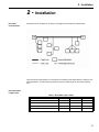

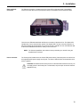

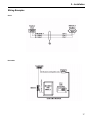

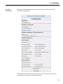
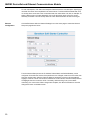
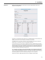
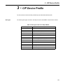
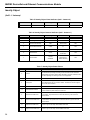
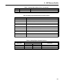

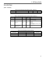
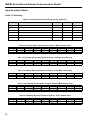

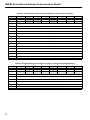
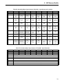
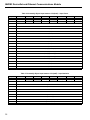

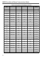
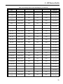

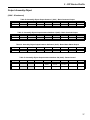
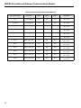
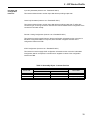
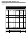

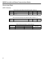
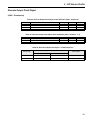
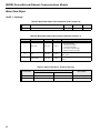
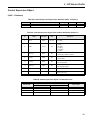
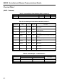
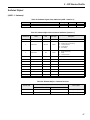

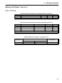
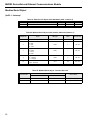
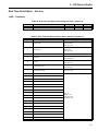
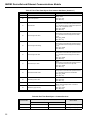
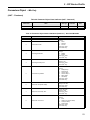
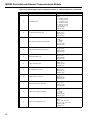
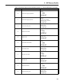
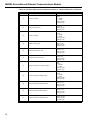
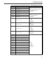
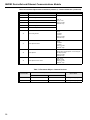


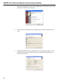
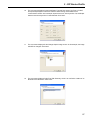

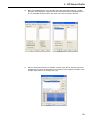
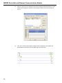

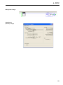
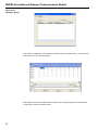

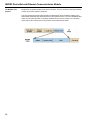
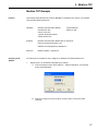


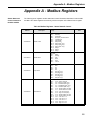
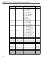

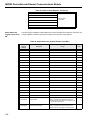
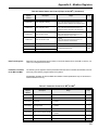
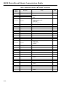
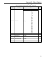
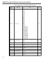

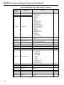


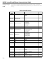
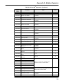
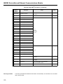
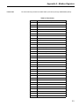
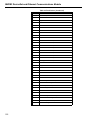

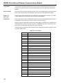


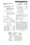


![EX MV MX3 User Manual [May16].vp](http://vs1.manualzilla.com/store/data/005646159_1-0d378a1c318c2dc00419aef6af60da73-150x150.png)