1
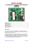
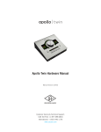
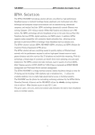
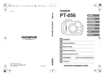
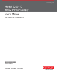
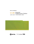
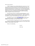
Smart Relay Controller
GPRS & HSRS Models
User Manual
Version 3.5
10/22/15
Copyright (C) 2010 - 2015
All rights reserved
Kenneth Delahoussaye Consulting
web: www.kadtronix.com
email: [email protected]
1
Table of Contents
Introduction..........................................................................................................................3
Enclosure and wall-mounting..............................................................................................6
HVAC Compatibility...........................................................................................................6
Setup for HVAC and similar applications............................................................................7
LED Indicators.....................................................................................................................8
DIP Switch Settings.............................................................................................................9
Definition of key terms......................................................................................................14
Concept of Operation.........................................................................................................15
Controller Reset.................................................................................................................16
Wired Sensors....................................................................................................................17
Wireless RF Option............................................................................................................21
Wireless Door/Window Sensor..........................................................................................25
Wireless Motion Detector..................................................................................................27
Wireless Registration.........................................................................................................29
Occupancy / Vacancy Detection........................................................................................32
Controller Testing..............................................................................................................34
Terminal Block Wiring Connections.................................................................................35
HSRS Wiring Installation..................................................................................................36
Detailed Wiring Instructions..............................................................................................37
Connecting a Wired Motion Sensor...................................................................................38
Sample HVAC Application #1 - Entire System Shutoff....................................................39
Sample HVAC Application #2 - Condenser Unit Shutoff..................................................40
Maintenance.......................................................................................................................41
Warranty.............................................................................................................................41
Disclaimer..........................................................................................................................41
Contact Information...........................................................................................................41
Revisions............................................................................................................................42
2
Introduction
WARNING: Only a qualified technician should attempt to perform the setup and
installation instructions contained in this manual. Your warranty may be voided if
damage occurs due to improper installation.
This manual describes setup and configuration operations for the Kadtronix family of
smart relay controllers. Please read these instructions carefully and thoroughly prior to
attempting installation. The following controller models are included in this family of
devices:
• General Purpose Relay Switch (GPRS)
• HVAC Smart Relay Switch (HSRS)
These controllers provide sensor-activated remote control capability for devices and
equipment. An onboard relay with SPDT contacts provides switching for loads up to 10A
@ 250VAC. Wired and/or wireless sensors may be employed.
While the GPRS is intended for general purpose use, the HSRS is designated for HVAC
applications. Information contained in this manual applies to both controllers unless
stated otherwise. When describing details that are generically applicable to both
controllers, the narrative refers to them in a collective sense as, "the controller".
The controller accepts wired and/or wireless switch sensor inputs. For wired sensors,
most any switch device having normally open or normally closed contacts is acceptable.
Mechanical sensors including reed, push-button, and toggle switches are also allowable.
TTL signals may also be used (active-low) in some cases. For applications where wire
runs are not desired or simply inconvenient, wireless sensors may be used (requires RF
receiver option). Intended for use with doors and windows, these sensors can also be
applied in a myriad of other uses where simple on/off detection is needed. You may even
use a mix of both wired and wireless sensor types.
For HVAC applications, available sensor types include door/window switches and motion
detectors. These sensors allow automatic shut-off if a door or window remains open for a
preset period of time. Motion detectors permit occupancy and/or vacancy detection. For
details on how to configure occupancy and vacancy modes for one or more motion
detectors, refer to "Wired Sensors" and/or "Wireless Registration".
Ideal for energy management, the controller reduces your power consumption when
sensor inputs are used with doors and/or windows in HVAC applications. For instance,
the controller can temporarily disable air conditioning or heating if a main entry door or
window has been open for a period of time.
The controller employs 16 configuration DIP switch settings for configuration purposes.
Accepting wired and/or wireless sensors, the controller can be set up to automatically
switch off an external circuit based on parameters you specify.
3
The controller device consists of electronic printed circuit board, enclosure, and 12VDC
adapter / converter: 120 VAC (for general-purpose applications) or 24VAC (for HVAC
applications). Optional wireless door / window sensors and companion receiver device
are also available.
WARNING: The controller contains static-sensitive electronics. When handling the
device, you should take proper precautions to prevent damage due to electrostatic
discharge. Use an approved anti-static wrist-strap or other protective appliance.
The following is a feature summary:
•
•
•
•
•
•
•
•
•
•
•
•
Electronic controller with intelligent micro-controller
On-board relay with SPDT contacts rated 10A @ 250VAC or 5A @ 100VDC
Accepts up to 4 wired inputs which can be zones or discrete switch sensors
Also accepts up to 8 optional wireless zones or individual sensor inputs (requires
RF receiver option)
Compatible with motion sensors for occupancy or vacancy detection
Configurable activate (relay on) and deactivate (relay off) delay periods
DB9 interface for wireless receiver (for use with optional wireless sensor
transmitters)
DIP switches for mode selection & configuring operational parameters (see
below)
Selectable activate / deactivate time periods: 0 to 10 hours (accuracy +/- 1%)
On-board mode and wireless-registration tactile switches
Piezo beeper with optional enable/disable DIP switch setting
External power adapter (120VAC for general purpose use or 24VAC for HVAC
applications)
4
Subsequent sections of this manual provide details for installation and configuration.
Before continuing, you should detach the enclosure cover (if applicable) and review the
location of DIP switches, terminal block wiring connector, and other components as
shown in the following image:
Controller components
5
Enclosure and wall-mounting
WARNING: The controller contains static-sensitive electronics. Please take
proper precautions to prevent damage due to electrostatic discharge. When
handling the controller, you should use an approved anti-static wrist-strap or
other protective device.
The controller includes plastic base-plate with mounting tabs and screw holes for
attaching to a wall or other surface. Locate a suitable space for mounting the
controller. The selection should be free from moisture, weather, vibration,
excessive temperature, and other hazards. It should also be easily accessible to
allow for occasional adjustments including DIP settings changes and/or wireless
registration updates. Use screws (not included) to attach the unit to the desired
surface.
IMPORTANT: Do not mount the system on an air handler unit or other metal
surface. If installing the HSRS wireless system, establish the maximum possible
separation of the antenna away from any metal objects.
HVAC Compatibility
The HSRS is compatible for use in most HVAC applications. However, you should be
aware of possible issues including those listed below:
PTAC and window a/c units are not always easy to interface with the HSRS
because these systems do not typically provide an accessible means of external
control by third party devices.
• Some HVAC manufacturers do not permit the use of third party controllers with
their equipment. To avoid warranty issues with your system, please consult the
manufacturer prior to installing the HSRS. (We accept no liability or responsibility
for issues or disputes with your HVAC supplier or manufacturer.)
•
6
Setup for HVAC and similar applications
Begin by disabling power to the HVAC equipment. If your controller includes an
enclosure, detach the cover. The controller contains on-board 14-pin screwterminal wiring block for connecting your HVAC equipment, input power, and
door/window sensors. (Refer to "Terminal Block Wiring Connections" for details.)
Connect the wires as required, noting proper terminal designations and polarities.
(Note: You will probably not require use of all 14 screw-terminal positions.)
Configure DIP switches as necessary for your application. (Refer to section titled,
"DIP Switch Settings" for details.)
IMPORTANT: To use wired sensors in your application, you must ensure that this
mode has been properly enabled at configuration DIP switch: DSW1, no. 8.
Refer to "DIP Switch Settings" for more information.
The controller requires a 12VDC power source. If your equipment does not
provide this voltage, you will need a compatible power converter module. Two
selections are available: 120VAC for general purpose use or 24VAC for HVAC
applications.
If you have purchased the wireless RF receiver option, refer to "Wireless
Receiver Option" for setup instructions. Refer to the remainder of this manual for
additional details concerning setup and operation.
Once you have completed setup and configuration, double-check your wiring and
DIP switch configurations. Then, re-attach the cover (if applicable). Re-enable
HVAC power to turn on the equipment and the controller.
Notes:
•
•
The section titled, "Sample HVAC Application" illustrates wiring details for
a central air conditioning system. For these applications, you have the
option of wiring the controller to shut off the entire system or only the
compressor, allowing the fan to continue to run.
To protect the compressor, you should invoke a minimum delay of 3 to 5
minutes before re-starting the system after shut-off. Refer to the subsection, "Deactivate Mode" in the "DIP Switch Settings" section for
additional information.
7
LED Indicators
The controller has a total of five light emitting diode (LED) indicators: one green
and four red. The green LED indicates operational status while the red LEDs
indicate sensor state. When the controller is powered on, the green status LED
flashes on and off at a periodic rate, indicating that the firmware is operational.
The green LED indicates the specific operational state of the controller as listed
in the table below:
•
•
•
LED On/
Off Rate:
Operational state:
-----------------------Slow, periodic
Normal operation (1 sec. on, 1 sec.
off, even duty-cycle)
Double-flash
Switch sensor triggered (on-off-on
100ms ea., off 1 sec.)
Solid On
Wireless sensor registration
(learn) mode
Each of the four red LEDs indicates open/closed status of a door, window, or
zone. For instance, LED #1 illuminates when the respective door opens and
extinguishes when it closes. When a red LED is on continuously (i.e., not
flashing), it indicates that the corresponding sensor is active, but a trigger
activation has not yet occurred. (Note: For a motion detector in occupancy or
vacancy mode, a red sensor LED will be on continuously when the sensor
detects motion and will extinguish when motion is no longer detected. When a
LED is on in vacancy mode, trigger is not imminent.)
When a red LED is flashing, it means that trigger activation has occurred (in
either a door/window or motion sensor). (Trigger activation means the onboard
relay has engaged and the device or equipment under control has been shut off.)
These LEDs may represent either wired or wireless sensors, as described in
"DIP Switch Settings". (Note: If you are using the wireless RF option and have
more than four wireless sensors, only the first four will be represented. Any
additional sensors will not be shown by the LEDs.)
8
DIP Switch Settings
There are two primary DIP switches: DSW1 and DSW2. DSW1 defines
operational mode, sensor activation states, and trigger activation configurations.
DSW2 defines trigger deactivation modes and configurations. In general, DIP
switch settings changes should be made only when the controller device has
been powered off. Do not attempt to make DIP settings adjustments while
the device is powered on.
------------------------Legend : 1=ON, 0=OFF
Default: All switches OFF
------------------------The following lists define available DIP switch settings:
-----------------------------------Trigger / Activation Settings (DSW1):
-----------------------------------------------------------1 2 3 4 5 6 7 8
Description
------------------------x x x x x x x 1
Wired-sensor disable
x x x x x x x 0
Wired-sensor enable
x x x x x x 1 x
x x x x x x 0 x
Sensor activation trigger state =
CLOSED (normally-open)
Sensor activation trigger state = OPEN
(normally-closed)
Note: For vacancy mode, the "OPEN" trigger state is
required (normally-closed contacts). Note that the
recommended use of switch contacts is reversed. For the
OPEN trigger state, trigger will occur when normallyclosed contacts remain closed. For details on
configuring a wired motion detector for vacancy mode,
refer to "Wired Sensors". For wireless motion detectors,
refer to "Wireless Motion Detectors".
9
x x x x x 1 x x
x x x x x 0 x x
Piezo/beeper disabled
Piezo/beeper enabled
x x x x 0 x x x
The 4 LEDs indicate wired sensor
states
The 4 LEDs indicate wireless sensor
states
x x x x 1 x x x
-------------------Sensor-active Period:
-------------------The sensor-active (ON) period below
indicates the amount of time that a
sensor must be in the active state
before a trigger occurs. ("Trigger"
means sensor is active & the relay is
energized, activating or deactivating
the external customer circuit via
relay contacts.) For HVAC
applications, this setting can be
used to provide a pressure
stabilization delay for the
compressor.
0
1
0
1
0
1
0
1
0
1
0
1
0
1
0
1
0
0
1
1
0
0
1
1
0
0
1
1
0
0
1
1
0
0
0
0
1
1
1
1
0
0
0
0
1
1
1
1
0
0
0
0
0
0
0
0
1
1
1
1
1
1
1
1
x
x
x
x
x
x
x
x
x
x
x
x
x
x
x
x
x
x
x
x
x
x
x
x
x
x
x
x
x
x
x
x
x
x
x
x
x
x
x
x
x
x
x
x
x
x
x
x
x
x
x
x
x
x
x
x
x
x
x
x
x
x
x
x
0 (instant)
1 sec.
5 sec.
10 sec.
30 sec.
1 min.
2 min.
5 min.
10 min.
30 min.
1 hour
2 hours
5 hours
10 hours
RESERVED
Indefinite (relay never energizes good for "offline" testing)
10
----------------------------Deactivation Settings (DSW2):
----------------------------------------------------1 2 3 4 5 6 7 8
Description
------------------------Deactivate mode defines the
conditions under which a trigger
activation may be extinguished
(cleared) and the relay de-energized.
x x x x x x x 1
x x x x x x x 0
x x x x x x 1 x
x x x x x x 0 x
---------------Deactivate Mode:
---------------Pulse
: time elapse only (sensor
revert to inactive not required)
Standard: sensor must revert to &
retain inactive state for elapsed
time period (see below).
Feature option enable (contact
Kadtronix for details)
Feature option disable (contact
Kadtronix for details)
11
---------------------Dual Timing Mode (DTM):
---------------------Dual timing mode (DTM) is a special
option that can be applied when a mix
of motion detectors and other sensors
(e.g., door/window, etc.) will be
used. In this mode, two different
activation delay periods can be
invoked. Motion sensor(s) will
utilize the traditional activation
setting as configured at DSW1 [DIP
switches 1-4]. However, other sensor
types (including door/window, etc.)
will derive their activation delay
period at DSW2 [DIP switches 1-4].
(Note: In normal mode, DSW2 defines a
deactivation delay period. DTM mode
overrides this function and does not
permit a deactivation delay. Instead,
a default deactivation period of 0
will be applied.)
x x x x x 1 x x
Dual timing mode (see description
above)
x x x x x 0 x x
Normal mode
12
------------------Elapsed Time-Period:
------------------The elapsed time (OFF) period
indicates the required elapsed time
period that must occur before the
relay can be de-energized. (In
addition, depending on the deactivate
mode setting above, the sensor may
also be required to be in the
inactive state). (For HVAC
applications, this setting can be
used to provide a pressure
stabilization delay for the
compressor.)
0
1
0
1
0
1
0
1
0
1
0
1
0
1
0
1
0
0
1
1
0
0
1
1
0
0
1
1
0
0
1
1
0
0
0
0
1
1
1
1
0
0
0
0
1
1
1
1
0
0
0
0
0
0
0
0
1
1
1
1
1
1
1
1
x
x
x
x
x
x
x
x
x
x
x
x
x
x
x
x
x
x
x
x
x
x
x
x
x
x
x
x
x
x
x
x
x
x
x
x
x
x
x
x
x
x
x
x
x
x
x
x
x
x
x
x
x
x
x
x
x
x
x
x
x
x
x
x
0 (instant)
1 sec.
5 sec.
10 sec.
30 sec.
1 min.
2 min.
5 min.
10 min.
30 min.
1 hour
2 hours
5 hours
10 hours
RESERVED
Indefinite (relay remains energized
until SC or PCR)
13
Definition of key terms
On-period = indicates the amount of time during which a triggered sensor must
be continually active before the event will be accepted and the relay energized.
Off-period = the amount of time that must elapse before the the relay is deenergized.
PCR = Power-cycle system reset is invoked by removing power to the controller
and then re-applying power. It causes the controller to reset all processing
activities.
WR = Wireless registration is the process required for initializing the controller to
recognize compatible wireless transmitter peripherals such as door/window
sensors. WR is invoked by tactile momentary switch.
RST = Controller reset is invoked by "Mode" tactile switch and forces an event
equivalent to power-cycle.
14
Concept of Operation
When the controller is powered on, it begins scanning sensor inputs for the
specified trigger condition (switch closed or opened depending on configuration
parameters). If sensor trigger occurs, the controller then determines (based on
configuration) whether or not relay activation / deactivation is to occur. Again
based on configuration, the controller may delay a preset time period before
taking any action. During this time, the signal may or may not be required to
remain continuously at the pre-specified activation / deactivation state
(depending on configuration).
For example, assuming these parameters:
•
Active = 5 min., Inactive = 1 min., Deactivate = Standard, Sensor
Act.= Open
Under these conditions, the controller will energize the relay when it determines
that a given sensor activation input remains continuously open for 5 minutes. It
will then de-energize the relay if the signal remains closed continuously for 1 min.
As another example, assume the following:
•
Active = 0 min., Inactive = 5 sec., Deactivate = Pulse, Sensor Act. =
Closed
Under these conditions, the controller will immediately (= 0 min.) energize the
relay when it determines that a given sensor input is closed. It will de-energize
the relay after 5 seconds, regardless of the input signal state.
As a last example, assume the following:
•
Active = 0 min., Inactive = Indefinite, Deactivate = either (standard or
pulse), Sensor Act. = Closed
Under these conditions, the controller will immediately (= 0 min.) energize the
relay when it determines that a given sensor input is closed. It will not deenergize the relay unless the controller is power-cycled (PCR).
15
Controller Reset
Controller reset is useful for clearing a trigger activation and disengaging the
relay. It can also be used to disable the controller. (Refer to hard reset below.) It
is functionally equivalent to a power-cycle operation.
IMPORTANT: This feature should be used primarily as a trouble-shooting
measure. It should not be performed unless the device or equipment under
control has been powered off or disabled.
There are two methods for invoking a controller reset:
•
•
Soft reset
Hard reset
To invoke a soft reset, press and hold the mode button for 3 seconds. The four
red LEDs will briefly illuminate and the beeper will sound, indicating offline mode.
Press and release the mode button once; then press and release the register
button to invoke the reset. (Red LED #1 will illuminate, indicating offline reset
mode.) The steps are summarized below for convenience:
•
•
•
Press/hold mode button for 3 seconds (offline mode)
Press/release mode once more
Press/release register button; reset occurs within 3 seconds
A hard reset requires the use of an external switch connected at wiring screw
terminals 2 (ground) and 3 (reset/disable). (Refer to “Terminal Block Wiring
Connections” for details.) The reset/disable input will cancel a relay activation
and reset the controller.
Apply a normally open switch (momentary, toggle, etc.) with sufficient wiring
pigtail at terminals 2 & 3. (For reset, a momentary switch is recommended. For
disable, a latching toggle switch is suggested.)
Notes:
•
•
The hard reset feature requires PCB hardware rev. 4 or higher.
Wiring pigtail should be kept as short as possible to minimize susceptibility
to electrical noise.
16
Wired Sensors
The controller accepts up to 4 wired sensor inputs. Each input may accept a
single sensor or a group (zone) of sensors wired in series or parallel. A myriad of
traditional switch sensors is compatible for use with the controller including reed,
push-button, toggle, limit, momentary, etc. Configuration DIP switch DSW1-7
(sensor activation trigger state) allows you to configure either normally-open or
normally-closed operation. If sensors are normally-closed, then trigger activation
is presumed when the sensor is open. If sensors are normally-open, then trigger
activation is presumed when the sensor is closed. (When using a motion detector
in vacancy mode, trigger activation is modified. Refer to "DIP Switch Settings" for
more information.) The table below summarizes sensor configurations:
----------------Sw. / Sensor Type:
----------------Normally-closed
Normally-open
-----------------Act.State (DSW1-7):
-----------------Open
Closed
----------Zone Wiring:
----------Series
Parallel
(Note: For HVAC applications, optional zone wiring is allowable only for detecting
open doors or windows. Do not attempt zone wiring for motion detectors in
vacancy mode. Use one-for-one wiring instead. That is, only one motion detector
may be wired to a single sensor input at the controller.)
Wired sensors may be employed for a number of uses. (Wired sensor operation
may be configured using DIP switches. Refer to "DIP Switch Settings". ) There
are several configurable modes listed below:
•
•
•
•
Door/window (or general-purpose) sensor
Motion (occupancy / vacancy) sensor
Delayed relay activation trigger mode
Priority relay activation trigger mode
Door/window mode is the default operational state. (No action is required to
configure this mode.) Door/window switches and general-purpose sensors can
be used.
(Note: For wiring information, refer to Detailed wiring instructions. If installing a
wired motion sensor, refer to "Connecting a Wired Motion Sensor" f.)
17
Occupancy & vacancy modes require specialized motion sensors. You must
assign the proper mode at the controller. To make this assignment for a given
sensor input, press and hold the mode button for 3 seconds. The four red LEDs
will illuminate and the beeper will sound, indicating offline mode. Press and
release the "Register" button indicating wired sensor mode. Red LED #1 will be
illuminated, indicating wired sensor input #1. (To advance the selection to
different wired sensor, repeatedly press and release the "Register" button until
the desired sensor LED is illuminated.)
Delayed activation trigger mode postpones relay activation and is applicable to
default sensors including door/window switches (wired and/or wireless). In this
mode, a trigger will not occur until the sensor returns to the idle (pre-trigger)
state. It is used in situations that require the sensor state to revert back to the
previous state before the relay is activated. (For proper operation, a non-zero
deactivation delay time period should be configured. Refer to “DIP Switch
Settings“ for additional details.)
For example, delayed triggering may be used in an automatic vent fan
application for a chemical mixing room. The entry door is equipped with a
magnetic reed door sensor that is connected to one of four available HSRS wired
inputs. The vent fan is controlled by HSRS relay and is to be activated only if a
worker enters the room and remains for at least 5 minutes (sensor-active period)
with the door closed. However, the fan must not activate until he opens the door
(delayed activation) and must continue to run for at least 10 minutes afterward
(deactivation time period). Here are the recommended DIP switch settings:
•
Active = 5 min., Inactive = 10 min., Deactivate = either (standard or
pulse), Sensor Act.= Closed
Priority activation trigger mode results in immediate relay activation when a
trigger condition exists for the specified sensor. In this mode, the sensor-active
trigger period in DSW1 DIP Switch Settings is ignored. However, for deactivation,
the sensor will use the deactivation time period configured in DSW2 DIP Switch
Settings.
18
To specify occupancy mode for the selected sensor input, press and release the
"Mode" button - two beeps will be sounded as confirmation.
To specify vacancy mode for the selected wired sensor input, press and release
the "Mode" button once, then again – two beeps will be sounded, then three
beeps.
To specify delayed activation mode for the selected wired sensor input, press
and release the “Mode” button again – four beeps will be sounded as
confirmation.
To specify priority activation mode for the selected wired sensor input, press
and release the “Mode” button again – five beeps will be sounded as
confirmation.
(Press and release a fifth time for the default mode (doors, windows, etc.) - one
beep will be sounded).
To save & exit, press and hold the register button for one second. The steps are
summarized below:
Press/hold mode button for 3 seconds (offline mode)
Press/release the register button to choose a wired sensor
Press/release the mode button to invoke occupancy mode (two beeps
are sounded)
Press/release the mode button again to invoke vacancy mode (three
beeps are sounded)
Press/release the mode button again for delayed trigger mode (four
beeps are sounded)
Press/release the mode button again for priority activation mode (five
beeps are sounded)
Press/release the mode button again for the default mode (door/window)
To exit, press/hold the register button for 1 second (3 beeps are sounded)
•
•
•
•
•
•
•
•
Notes:
•
•
•
Subsequent configuration attempts will erase any previously stored
settings from non-volatile memory.
If you will be using only wireless sensors and will not be using any wired
sensors, you may disable these inputs. (Refer to "DIP Switch Settings" for
details.)
If you are using wired sensors, but will not be using all 4 of the available
19
•
•
•
inputs, then it is imperative to properly handle the unused inputs. If the
sensor activation trigger state DIP switch is configured "open", then any
unused inputs should be wire-shorted to one of the wired sensor return
terminals. If the sensor activation trigger state DIP switch is configured
"closed", then unused inputs should remain unconnected.
If you will be using no wired sensors, you may simply disable them.
(Refer to "DIP Switch Settings" for details.) Once disabled, wire-shorting
will not be required.
The controller must be configured for the exclusive use of either normallyopen or normally-closed switch sensors. Do not attempt to use a mix of
both switch sensor types.
If you will be using motion detectors in vacancy mode, be sure to specify
the OPEN trigger state (DSW1, switch 7). Refer to "DIP Switch Settings"
for details.
IMPORTANT: To use wired sensors in your application, you must ensure that this
mode has been properly enabled at configuration DIP switch: DSW1, no. 8.
Refer to "DIP Switch Settings" for more information.
20
Wireless RF Option
A wireless receiver option is available for use with compatible RF sensor
transmitters. The following components are included:
•
•
•
•
•
•
•
•
Controller
Power converter: 110VAC or 24VAC (for HVAC)
RF Receiver (310 MHz)
Receiver power cable, 12"
Antenna, quarter wave whip
Mounting bracket for antenna
Coax antenna cable
One or more door/window transmitters
There are two possible receiver models (shown below). Type-A is the original
model and features compact design and direct attachment to the HSRS
controller. (Interface cable is not required for this model.) Type-B is the next
generation receiver that features LED indicator and enhanced reception. This
model requires serial interface cable (included) for connection to the HSRS
controller. Both models include external whip antenna with coax cable.
Receiver
(type-A)
Receiver
(type-B)
Antenna with
coax cable
IMPORTANT: The system is extremely sensitive to RF signals. It is imperative
that other wireless devices are kept far away from the receiver and antenna.
Items including cell phones, wi-fi routers, and remotely controlled gadgets can
obstruct or even jam signal reception.
21
Compatible wireless transmitter devices include the following:
•
•
•
Door/window sensors
Infrared motion detectors
Key fob transmitters
The picture below shows a complete setup for wireless operation. It includes
controller, power converter options, wireless RF receiver, and accessories:
22
The list below denotes HSRS equipment and optional hardware. (Corresponding
items in the picture above have matching numbers for easy identification.)
1)
2)
3)
4)
5)
6)
7)
8)
9)
HSRS controller
Receiver power cable
Wireless receiver
Door/window transmitter
110 VAC converter
Whip antenna with “L” bracket
Receiver interface cable
24 VAC converter
Antenna cable
Notes:
1) The power converter provides proper voltage to the HSRS controller. Only
one of the two converters shown will be needed in any given application.
2) There are two possible receiver models as previously described. Type-B is
shown in the picture.
3) The receiver interface cable connects the wireless receiver to the HSRS
controller. This cable is required for the type-B receiver but is optional for
type-A. (The type-A receiver can be plugged directly into the HSRS
controller.)
Use the following procedure to install a wireless system:
•
•
Connect one end of the receiver interface cable (7) to the HSRS
controller (1) at the male 9-pin connector. Attach the other end to the
receiver (3) at its female 9-pin connector.
Locate the receiver power cable (2). (One end of the cable contains a
1/8" male plug and the other is pre-wired to the controller.) Insert the male
plug into the corresponding connector jack at the receiver (3).
Note: If the receiver power cable has not been pre-wired, then strip 1/4”
from both wires and insert the wire with white stripe at screw terminal 1
and the plain wire at terminal 2.
•
•
Use double-sided foam tape to mount the receiver unit to a wall or other
smooth surface.
Install the whip antenna using the mounting bracket (included) and
suitable screws (not included).
23
IMPORTANT: Be sure to position the receiver and antenna away from
metallic items, electrical equipment, phones, computers, and other
possible obstructions and sources of radio interference. Do NOT install
the antenna on or inside a metal cabinet as this will severely impede its
efficiency.) Position the antenna vertically, and locate near the ceiling or
as high as is allowable for receiving sensor signals. If possible, centrally
locate the antenna so that all door/window transmitter(s) are within 50
feet. (Note that walls and other obstructions will attenuate the RF signals
and limit signal range.)
•
Two antenna mounting schemes are available: direct-attach and
traditional wall-mount. Direct attach allows you to connect the antenna
directly to the receiver device and does not require interface cable, coax
antenna cable, or "L" bracket. Only a RG6 coupler is needed. Wallmounting permits attachment to a wall or other permanent surface and
requires "L" bracket and coax antenna cable. Choose the desired method
in one of the two following directives:
IMPORTANT: If you have a type-A receiver (described previously), you
may use either direct-attach or wall-mounting. For the type-B receiver,
you should use the wall-mounting method.
•
•
If direct-attaching the antenna, obtain a standard RG6 male-to-male
coupler/adapter. Attach the antenna (6) to one end of the coupler and the
RF receiver (3) to the other end. (Note that the interface cable, antenna
cable, and "L" bracket will not be needed.)
For traditional antenna wall-mounting, locate the "L" bracket at a suitable
location on the wall. Mark the location and attach the bracket using
compatible screws (not included). Then, attach the antenna to the
bracket. Next, attach one end of the coax antenna cable (9) to the
antenna (6) and the other to the receiver (3). Route the cable so that it is
out of the way, being careful to avoid damage due to scrapes, twists, or
sharp bends.
24
Wireless Door/Window Sensor
The wireless door/window sensor is a transmitter device that is compatible with
GPRS and HSRS controllers. There are two compatible models: compact (shown
left) and standard (shown right). The standard model uses an externally wired
magnetic switch (included) and accepts AA batteries.
The compact sensor model contains an internal magnetic switch. This model is
slightly smaller than the standard model and uses AAA batteries. It is a dualchannel device that also accepts optional external switch (or zone). Convenient
screw terminals are provided for this purpose. (A wire jumper has been preinserted at these terminals. If an external switch will be used, this jumper must be
removed.) Both internal and external switch channels are completely
independent of one another. As a result, they behave as if they were two
separate sensor devices. (Note: If both internal and external switches are used,
the sensor must be registered twice: once for each method. Refer to "Wireless
Registration" for details.)
To install the device, attach sensor unit to the stationary wall or frame adjacent to
the door or window being protected. Position the unit as high as possible and
secure with screws provided. Next, mount the magnet on the door or window,
being sure to align with the sensor unit. (Ensure that the inscribed arrow
indicators are facing each other and aligned so that they separate cleanly when
the door or window is opened.)
Wireless door / window sensors (compact & standard)
IMPORTANT: When installing the sensor device, the magnet should be mounted
on the door or window and the sensor unit attached to the stationary frame. In
the interest of minimizing mechanical shock, the sensor unit should never be
attached to the door or window. Doing so can result in premature failure of the
25
unit and may void your warranty.
Open the front cover to expose the battery compartment and switches. The
standard device has a hinged front cover. The compact unit has a snap-on front
cover which can be removed as follows: grasping the top end of the unit,
squeeze the back half with the left hand while separating the front half with the
right hand. (Or, insert a coin into one of the side-slots and gently turn to separate
the two portions.)
Set the DELAY slide switch to the MIN position and install alkaline batteries.
Press and hold the internal push-button switch several seconds and release. The
sensor indicator will flash indicating that the unit is ready and working properly.
(The device transmits status information each time the door / window is opened
or closed. It also auto-transmits this information at regular intervals of
approximately 45 minutes.) Refer to "Wireless Registration" for additional setup
details concerning wireless sensors.
IMPORTANT: When a wireless sensor/transmitter emits a message to the RF
receiver, there can be a delay of 5 seconds before the controller accepts the
message and illuminates the appropriate red sensor LED.
Batteries should be replaced once every two years on average or more
frequently as needed. (After replacing batteries, you will need to re-register ALL
wireless transmitter devices as described in "Wireless Registration".)
26
Wireless Motion Detector
Wireless motion sensors may be employed for occupancy / vacancy detection.
The wireless motion sensor is a specialized device with a transmitting range of
100 ft. (Range may be reduced by obstructions including walls and large metal
objects.) The device detects movement using infrared sensing technology. To
install the device, attach to a wall approximately 6 feet or so above the floor.
(IMPORTANT: Do not locate the unit near an air vent, heater, or other venue that
might interfere with infrared detection.)
Wireless motion sensors
Open the front cover and install AA alkaline batteries. At the back of the unit, set
the slide switch to position "1" (recommended) for maximum detection sensitivity
or "2" for lower sensitivity. (Position 2 may be necessary if you encounter false
detections. Refer to "Occupany / Vacancy Detection" for details.) Press and
release the TEST button. The red indicator will flash indicating that the unit is
operational. (The "Code" button on the back of the detector resets the internally
stored ID code. After completing wireless registration, you should NOT use this
button as it will cause the controller to lose recognition of the detector. Should
this occur, you would need to perform a new wireless registration operation.)
Refer to "Wireless Registration" for additional setup details concerning wireless
sensors.
27
IMPORTANT: When a wireless sensor/transmitter emits a message to the RF
receiver, there can be a delay of 5 seconds before the controller accepts the
message and illuminates the appropriate red sensor LED.
Batteries should be replaced every two years on average or more frequently as
needed. (After replacing batteries, you will need to re-register ALL wireless
transmitter devices as described in "Wireless Registration".)
28
Wireless Registration
Wireless registration is the process whereby the controller identifies compatible
wireless transmitter devices and stores their code identifiers in non-volatile
memory. (Wireless RF receiver is required.) This process is a prerequisite for
using the wireless sensor option and must be performed when any of the
following conditions occurs:
•
•
•
New installation
Sensor battery replacement
Adding sensor(s)
IMPORTANT: The system is extremely sensitive to RF signals. It is imperative
that other wireless devices are kept far away from the receiver and antenna.
Items including cell phones, wi-fi routers, and remotely controlled gadgets can
obstruct or even jam signal reception. Do NOT attempt wireless registration if
such devices are nearby.
Registration also guarantees that signals from nearby non-registered transmitters
will not cause unwanted triggering since only those devices which have been
registered will be recognized by the controller. Signals received from any nonregistered transmitters will be ignored. This processing is essential in allowing
error-free operation in environments where multiple controllers may be in use.
Examples of such venues include apartment buildings, hotels, and other multiunit facilities.
Compatible wireless transmitter devices include door/window sensors, key fobs,
motion detectors, etc. The controller may accept up to 8 wireless
sensor/transmitter devices during registration. If you have not already done so,
insert batteries for each device to be registered. (Note: Each transmitter device
auto-generates and stores a unique internal identifier code after installing new
batteries.
If the batteries in any single transmitter are depleted, removed, or replaced, you
must repeat the registration (i.e., re-register) procedure for ALL transmitters.
Therefore it is recommended that batteries in all units should be replaced at the
same time, preferably every 12 month to 24 months on average.) After installing
the batteries, double-check them for the prescribed polarity.
29
IMPORTANT: Registration is necessary only when adding new transmitters
and/or replacing batteries in existing transmitter(s). It is NOT necessary in the
event that power has been lost to the controller. This is because the controller
stores registration information in non-volatile memory and simply recalls the
information on the next power-up sequence.
Before continuing, be sure that the controller is powered off. Remove the cover
from the controller's enclosure housing (if applicable). Then, connect the RF
receiver to the DB-9 connector of the controller. Connect coax antenna cable
between the receiver and the whip antenna. Attach the short power cable from
the controller to the back of the receiver (if applicable).
Now, power on the controller. The green LED indicator at the controller should
flash on and off at a periodic rate. Locate the controller's on-board tactile switch
labeled, "Register" - press and hold for 3 seconds. The beeper briefly
annunciates and the green LED will remain on steady (i.e., no flashing). The 4
red LED indicators will be off. The controller is now in wireless registration mode.
Next, obtain a wireless transmitter/sensor device to be used in your application.
After inserting batteries, perform a test transmission. On door/window & motion
sensors, the simplest way to do this is through magnetic switch activation.
Magnetic activation is performed by moving the magnet toward the sensor. This
causes the unit to initiate a wireless transmission, as evidenced by rapidly
flickering LED on the sensor.
IMPORTANT: The compact sensor model allows for an optional external switch.
(Refer to "Wireless Door/Window Sensor".) If using both internal and external
switches with this model, you must perform an additional registration for the
external switch. Register the external switch by performing a magnetic
activation.)
30
If using a key fob or other hand-held transmitter, perform the test by pressing any
available button on the unit. This action will initiate a RF transmission that will be
detected by the wireless receiver and passed along to the controller. When this
occurs, one of the four red LED indicators at the controller will be illuminated
indicating that the transmitter device has been detected, registered, and saved in
controller non-volatile memory. If the sensor is a motion sensor that you wish to
use for occupancy detection, press/release the "Mode" button. The beeper will
sound two times. If vacancy detection is desired instead, press/release the
"Mode" button again. The beeper will sound three times. The steps associated
with wireless registration are summarized below:
•
•
•
•
•
•
Press/hold register button for 3 seconds (offline wireless registration
mode)
Activate the sensor. (For door/window sensor, bring the magnet in close
proximity to the transmitter and then separate them. For a motion sensor,
press the TEST button.)
If motion detector, occupancy mode, press/release the mode button
(green LED flashes & beeper sounds twice)
If motion detector, vacancy mode, press/release the mode button once,
then press again. (green LED flashes & beeper sounds three times).
Repeat the previous three steps for each additional wireless
transmitter/sensor device.
To exit wireless registration, press/release the register button
IMPORTANT: When a wireless sensor/transmitter emits a message to the RF
receiver, there can be a delay of 5 seconds before the controller accepts the
message and illuminates the appropriate red sensor LED.
Notes:
•
•
Subsequent wireless registration attempts will erase any previously
stored transmitter devices from non-volatile memory.
If you will be using motion detectors in vacancy mode, be sure to specify
the OPEN trigger state (DSW1, switch 7). Refer to "DIP Switch Settings"
for details.
31
Occupancy / Vacancy Detection
Motion detector devices are required in applications where occupancy or
vacancy determination is needed. Wired and/or wireless detector types may be
used. While both types yield the same basic functionality, they differ in their
method of issuing detection notifications to the controller. Wired sensors offer a
limitless number of detection opportunities to the controller and are therefore able
to detect motion at any time. Wireless motion detectors, on the other hand,
provide detection opportunities every 30 seconds or so, meaning that after a
detected event, the device will not detect another event for at least that period of
time. This helps to preserve battery life since RF transmissions consume a
significant amount of power. In occupancy mode, trigger activation (i.e.,
equipment shut-off) occurs when ANY detector senses motion. (Refer to "Wired
Sensors" and/or "Wireless Registration" for information describing how to
configure occupancy mode.)
The controller also provides a special vacancy mode which is particularly useful
in HVAC applications. Vacancy is assumed when there has been no detected
motion by ANY motion sensor for a preset period of time. When this mode is
invoked, trigger activation occurs only when ALL vacancy-configured sensors
have detected vacancy. Trigger release (i.e., equipment re-activation) occurs
when ANY detector picks up occupancy (i.e., motion). The vacancy mode feature
is useful for shutting down equipment when all rooms have been unoccupied for
a preset period of time. The equipment can be re-activated when any motion
sensor detects occupancy (i.e., movement). (Refer to "Wired Sensors" and/or
"Wireless Registration" for information describing how to configure vacancy
mode.)
Note: If desired, the equipment can be automatically reactivated after a preset
delay. (Automatic reactivation requires “Pulse” deactivation mode.) This can be
useful for maintaining an adequate comfort level in the space. For details on
configuring time delay periods, refer to "DIP Switch Settings".
For example, consider a vacation rental property requiring HVAC shut-off when
the space has been vacant for a period of time. To properly implement vacancy
detection, motion sensors should be provided in primary areas including kitchen,
living room, and bedrooms. In addition, it is necessary to allow sufficient
detection time to minimize the possibility of false vacancy determination.
Note: Night time occupancy/vacancy status can be difficult to ascertain once
occupants have gone to bed. It is imperative to prevent the controller from falsely
assuming vacancy and shutting down the HVAC system. Therefore, when
installing a detector in a bedroom, consider locating the device so that it is able to
32
detect any subtle movements by sleeping occupants. This can be effectively
accomplished by placing the unit on an opposing wall in front of the bed and at a
height of approximately 6 to 8 feet above the floor. Configure a sensor-active
period of 2 hours or more to prevent false vacancy determination. (Refer to the
sensor-active period described in the "DIP Switch Settings" section for details.)
For information describing how to configure vacancy mode for one or more
motion detectors, refer to "Wired Sensors" and/or "Wireless Registration".
In some situations, a single detector may not be sufficient for monitoring a larger
room or space. In these instances, a dual detector solution may be required. In a
large bedroom, for instance, a ceiling-mounted detector can be applied above the
headboard for night monitoring while a second wall-mounted device is placed at
another location within the room to monitor daytime activity.
IMPORTANT: Infrared motion sensing devices can detect many different heat
sources. To prevent false detections, avoid facing sensors directly into these
sources:
•
•
•
•
•
•
•
Dryers
Heaters
Sunlight
Furnace vents
Kitchen appliances
High wattage lighting
Windows
For wireless motion detectors, you can also adjust the detection sensitivity. Refer
to "Wireless Motion Detector" for more information.
33
Controller Testing
(IMPORTANT: Prior to performing testing, you should deactivate the equipment
under control. For an HVAC unit, this can be done by shutting off the system at
the thermostat. Or, you may detach wires at controller terminals 12, 13, 14.)
•
•
•
•
•
Begin by powering off the controller and ensuring that all sensors are
inactive (e.g., doors and windows closed).
Next, power on the controller and examine the LED indicators. The green
system status LED should be flashing on and off at a steady rate. The
four red LEDs should be off.
Now, invoke an activation by "tripping" a sensor (e.g., open a door or
window). After a pre-defined delay (as defined by your DIP Switch
Settings), the relay will engage and the beeper will briefly sound (if
enabled).
Reset the sensor back to its normal (non-triggered) state. After a predefined delay (as defined by your DIP Switch Settings), the relay will
disengage and the beeper will briefly sound (if enabled).
Repeat the prescribed test sequence for each additional sensor.
When you have completed testing, you may re-enable the equipment under
control.
34
Terminal Block Wiring Connections
The controller provides screw terminal connections for wiring purposes:
1)
2)
3)
4)
5)
6)
7)
8)
9)
10)
11)
12)
13)
14)
+12VDC power in/out
Ground
Reset/Disable
Wired Sensor #1
Wired Sensor #2
Wired Sensor #3
Wired Sensor #4
Wired Sensor return
Wired Sensor return
Wired Sensor return
Wired Sensor return
Relay - COM
Relay - N/C
Relay - N/O
Notes:
•
•
•
Wiring screw terminal #1 is labeled on the controller board and is located
at the corner nearest the two tactile switches.
The reset/disable input will cancel a relay activation and reset the
controller. Connect a normally open switch (momentary, toggle, etc.) at
wiring terminals 2 & 3. (Refer to "Controller Reset” for additional details.)
In most instances, only a subset of the available wiring connections will be
required in a given application.
35
HSRS Wiring Installation
Installation is straightforward, requiring 1 to 2 hours of labor by a qualified HVAC
technician or electrician. The HSRS controller should be mounted near the indoor
air handler with appropriate low-voltage wiring routed into the HVAC unit for
direct access to the system's 24vac power supply. The schematic below
illustrates the simplicity of a typical HSRS installation:
36
Detailed Wiring Instructions
The following instructions demonstrate wiring installation for a typical split system
central air conditioning unit. (Caution: Although HSRS wiring is not complicated,
only a qualified HVAC technician or electrician should attempt the procedure. The
following items will be needed: screwdriver, wire cutter / stripper, splicing
connectors, several feet or more of low-voltage wiring.
Disclaimer: These instructions are typical, but do not apply to every system. We
assume no responsibility for damage or injury due to possible inaccuracies or
misinterpretations pertaining to information contained in this manual. The
installer is ultimately responsible to fully understand the HVAC system
schematics and to conduct proper wiring modifications for HSRS implementation.
•
•
•
•
•
•
•
•
•
•
•
•
•
•
•
Remove cover from the HSRS controller.
Shut off power to the a/c system.
Remove front cover from the indoor+ air handler unit.
Locate low voltage (24vac) wires originating from the transformer.
Cut and strip two wire segments of desired length. (The wires should be
long enough to extend to the outside of the air handler for connecting to
the external HSRS controller.)
Using splicing connectors, join each segment in parallel with each of the
two existing 24v output wires from the transformer.
Connect remaining ends of the spliced wire segments into HSRS power
converter (white screw terminal block).
Cut one of the existing 24v transformer wires of the air handler, creating
two loose wire ends. (Note: Be sure to cut the wire downstream of (past)
the spliced connection you made in the previous step. Inadvertently
cutting the wire upstream of the connection will have an adverse effect on
the a/c system when a door/window violation occurs.)
Strip the two loose wire ends. (If necessary, extend the loose ends using
additional wire segments and splicing connectors.)
Connect one wire end to HSRS terminal 12.
Connect the remaining wire end to terminal 13.
If using a wired door/window sensor, connect the sensor wires to
terminals 4 & 8. Additional sensors should be wired to terminals 5 & 9, 6
& 10, and 7 & 11. For a wired motion sensor, refer to "Connecting a Wired
Motion Sensor". (For wireless door/window sensors, refer to "Wireless
Door/Window Sensor".)
Replace air handler front cover.
Replace HSRS cover.
Restore a/c system power.
37
Connecting a Wired Motion Sensor
A wired motion sensor requires a total of four (4) wires for installation: power
(12vdc), ground, and two switch contacts (NC & C). An external 12vdc power
source is required. We recommend powering the unit directly from the HSRS
controller. (Or, if preferred, you may use an optional ac power adapter [i.e., "wallwart"].) The table below summarizes the wiring connections and assumes the
HSRS controller provides 12vdc power directly to the sensor.
Wiring
Item
Sensor
HSRS
connections connections
Switch contacts *
NC, C
“Wired Sensor” terminals
Power
12V, GND
Terminals 1 & 2
* - Utilize the sensor's normally-closed (NC) contact if the HSRS sensor
activation trigger state = OPEN (default). Otherwise, use the sensor's normallyopen (NO) contact.
38
Sample HVAC Application #1 - Entire System Shutoff
The following schematic illustrates how to wire the HSRS controller in an HVAC
application with two monitored doors. When violation occurs, the entire HVAC
system will be shut off. (This sample presumes the use of normally-closed door
sensors and controller activation trigger state = OPEN.)
39
Sample HVAC Application #2 - Condenser Unit Shutoff
The following schematic illustrates how to wire the HSRS controller in an HVAC
application with two monitored doors. When violation occurs, only the outdoor
condensing unit (including compressor) will be shut off. (This sample presumes
the use of normally-closed door sensors and controller activation trigger state =
OPEN.)
40
Maintenance
The product requires no special maintenance other than protection from weather,
moisture, power surges, and hazardous environments.
Warranty
This product is warranted for a period of 1 year from the date of purchase and is
guaranteed to be free from defects. The warranty covers the entire unit, except if
any part or component has been modified or otherwise converted from its original
form. The warranty does not cover damage or failure due to neglect, improper
use, electrostatic discharge, unshielded exposure to moisture, power surges,
hazardous environments, and the like.
Note: The customer is responsible to provide protection against over-voltage
situations including power surges, spikes, and lightning strikes. The use of
adequate surge protection is recommended.
Disclaimer
Neither Kadtronix or Delahoussaye Consulting shall be held liable or responsible
for incurred damage or injury which may result due to the use or misuse of the
product or due to possible inaccuracies or misinterpretation of information
contained in this manual.
Contact Information
Should you have any questions or comments please contact us at:
Delahoussaye Consulting
http://www.kadtronix.com
[email protected]
41
Revisions
Rev.
Date
Comments
1.0
5/11/10
Initial release
1.1
5/30/10
Added revision history
Changed definition of the relay-test switch to self-test
Changed definition of the reset switch to registration
Modified wireless registration description: invoked by
tactile switch instead of DIP switch no. 8
Changed purpose of DIP switch DSW1, no. 8, formerly
wireless registration, to wired-sensor enable
Updated DIP switch references so they are
unambiguous
1.2
6/4/10
Modified descriptions associated with tactile switches:
self-test and wireless registration.
1.3
6/11/10
Added "System Testing" section. Clarified definition of
LEDs.
1.4
6/24/10
Adjusted no. of wireless sensor inputs from 10 to 8.
1.5
6/28/10
Changed definition of tactile switch from "self-test" to
"mode".
1.6
7/1/10
Added details for using motion sensors for occupancy
detection.
1.7
7/6/10
Added details concerning motion sensors. Explained
distinction between occupancy and vacancy modes.
1.8
6/5/11
Added re-activate / deactivate period of 10 hours. Also
added section titled, "Occupancy / Vacancy Detection".
1.9
7/4/11
Updated occupancy & vacancy mode descriptions.
Removed self-test mode description and references.
2.0
8/6/11
Updated sample HVAC schematic.
2.1
9/27/11
Applied images and updated text for additional wireless
sensors. Inserted additional sample HVAC schematic.
2.2
10/11/11
Updated installation description for wireless sensors.
2.3
2/21/12
Added detailed wiring instructions
Corrected page numbering issue
42
Rev.
Date
Comments
2.4
2/21/12
Updated details pertaining to compact wireless sensors
2.5
3/10/13
Added delayed trigger (return-to-idle) mode
Added priority (immediate) trigger mode
Re-formatted the document
2.6
4/7/13
2.7
7/17/14
Changed title-page photo.
Modified descriptions to include the type-B wireless RF
receiver upgrade.
Re-formatted the document
Updated DIP switch descriptions, reversing the switch
numbering.
Also added description for DIP switch: DSW2-7.
2.8
10/11/14
Corrected instructions for vacancy mode configuration.
Also updated text formatting.
2.9
03/12/15
Added a note describing optional automatic reactivation
for occupancy/vacancy modes.
3.0
04/16/15
Added wiring details for wired motion sensors.
3.1
04/25/15
Added dual timing mode (DTM).
3.2
05/09/15
Minor editorial correction in Wireless Registration.
3.3
06/10/15
Additional editorial updates.
3.4
09/09/15
Added wiring installation section with schematic.
3.5
10/22/15
Replaced photos to show the new enclosure.
43