1
Photo3D User's Manual
There are two menu items in the menu bar at the top of Photo3D's window, File menu and Mode menu.
1. File Menu
1.1 Load Image
"Load Image" invokes file selection box to specify the file name of image data file. For now SGI's .rgb format is
required for the image data. The loaded image is always displayed as background except for Preview mode. All
images you load are displayed as thumbnails at the top of the window. To switch among these images, simply click
the thumbnail.
1.2 Save Model
"Save Model" invokes file selection box to specify the file name of model data. Model data contains all information
you have specified using Photo3D. Thus, you can quit your session after saving model and resume by loading the
model. File name for model data should have extent ".mdl".
1.3 Load Model
"Load model" invokes file selection box to specify the file name of model data to load.
1.4 Output VRML
The 3D model created by Photo3D can be output as a VRML 1.0 format file. "Output VRML" invokes file selection
box to specify the file name of VRML. The file name extent must be ".wrl". Sorry, for the current version, the extent
is not attached automatically. Please key in manually.
2. Mode Menu
There are five modes to create 3D model and preview the resulting model.
Calibration
Positioning
Model
Texture
Preview
For each mode, buttons corresponding to functions used in the mode are displayed at the top of the window.
Calibration
In this mode, we setup the relation between the image and the 3D space.
Positioning
In this mode, we give supplementary information to calibration step needed to create 3D model from multiple
photos.
Modeling
1
In this mode, we create 3D model with the aid of image as background.
Texture
In this mode, texture data for surfaces of the model are created.
Preview
In this mode, we examine the resulting 3D model from various view point.
Tools
Besides the buttons shown above, there are four tool buttons to help operations. Some of them are only available in
certain steps.
3. Calibration
When an image data is loaded, it is immediately displayed in the main drawing area together with three pairs of line
segments (six line segments). We shall call the line segments frame lines, because they determine the framework
of 3D space. Each pair is colored in Red, Green and Blue respectively. Each pair corresponds to one of three
mutually orthogonal directions x,y and z.
Each line segment (frame line) has small circles at the ends and a short arrow near the midpoint of it. By picking
one of the small circles and dragging it without releasing the mouse button, you can move an end point of a frame
line. By picking and dragging an arrow, you can move a frame line parellelly.
For each direction of x, y and z, choose two lines in the image that are parallel to the direction. To be parallel, here,
doesn't mean parallel on the screen, but parallel in the 3 dimensional world. Move frame lines to fit the chosen lines
in the image. To get better precision choose:
as long lines as possible
If you choose a short line segment, even a slight error of end point position causes a significant error of
direction.
as distant pair of line segments as possible
Suppose there are a lot of parallel lines. If you choose adjacent two lines which are nearly parallel also on
the 2D image, the cross point of the two is unstable.
as reliable lines as possible
For example, an edge line of a big building is more likely to include less directional error rather than a pillar of
a hut.
Color usage for vertical and horizontal directions
Vertical direction must be specified by blue pair of frame lines, while two horizontal directions are specified by either
of red or green pair. You don't need to worry about which is red and which is green.
Tips for quick and precise fitting
2
Magnet Mode
In magnet mode Photo3D searches an
For quick fitting, turn magnet mode on by pushing the magnet button.
edge in the image near the current position of frame line, and automatically modifies the position of the frame line to
fit the detected edge. The modification occurs when the mouse button is released. This mode can be turned off by
pushing the button once more.
Mouse Sensitivity
For precise positioning of frame lines, decrease the mouse sensitivity by entering a small value in prefix window.
For example, by setting value 0.01 the mouse cursor gains as 1/100 distance compared to the default setting where
the prefix value is set to be 1.
Magnifier
To see magnified image, activate the magnifier window by pushing the magnifier button.
The area to be
magnified is indicated by a red rectangle in the main drawing area. The area can be moved by picking and dragging
the boundary of the red rectangle. The magnifier window can be resized by usual window operation --- picking and
dragging a corner of the window. This window can be turned off by pushing the magnifier button once more.
Stretcher
In some cases it is difficult for the magnifier to see a magnified image of a long line. In such a case, please use
strecher instead of magnifier.
Strecher is an another type of magnifier. The rectagle to be magnified can be placed obliquely in the main window,
and this region is mapped into a square in the auxiliary window. Thus a thin rectangle along a long line is shrinked
along the line and stretched in the perpendicular direction.
It is the perpendicular direction that matters when you are trying to fit a frame line to an edge in the background
image. Thus with this tool you can check if the frame line fits to the edge.
This tool is also used to correct the lens distortion. For detailed description on the stretcher, see the section of
"Correcting lens distortion".
The following explanations are on the operations needed for special interest to pursue the precision of the
calibration. Thus for the first time reading, the rest of this section may be skipped.
Examining the Fitting
For each direction of x, y and z, we have chosen only two lines in the image. However, in general, there are many lines parallel to the
direction. For example walls of a building have many parallel lines made up of window frames. In examining mode we can check
whether the the direction determined by the two lines matches also with the remaining lines.
In order to examine one of the three direction, turn examining mode on, by pushing the examining button.
Pick one of the frame
line to indicate which direction you are going to examine, then drag the mouse without releasing the mouse button. This operation does
not affect the picked frame line. Instead a new line segment will appear with one end at the mouse cursor, another end at the vanishing
point --- cross point of chosen two lines. Move the cursor so that the new line segment overlaps one of the remaining lines which you
wish to examine. This mode can be turned off by pushing the button once more.
Determining by choosing more than two lines
We used only two lines to determine the direction. In examining mode mentioned above, other lines parallel to the direction were used
only for checking the result. By letting these lines participate to determine the direction, we can expect more stable estimation.
3
To accomplish the task we need the following steps:
Add another frame line
Enter into the copy mode by pushing the copy button.
Pick one of the frame line which belong to the direction you wish to
add another frame line. Then a new frame line will be created, which is invisible at first because it is created at exactly the same
position as the picked one. The mode automatically turn from copy mode into usual mode (mode to move frame lines).
Move the added frame line
Move the added frame line by usual operation to one of the remaining line in the image which is parallel to the direction in
question. Since the frame lines, including the added one, are parallel in 3D space, they should cross each other at a single
point --- vanishing point. Or, in geometric terminology, they should be concurrent. However they are not exactly concurrent
because of various kind of errors, most likely because of error of fitting. In the following we focus on the fitting error and try to
eliminate, or decrease at least, this kind of error. (There are other kind of errors; For example, strain of image typically caused
by lens distortion, and dimensional error of the object in the world itself.)
Check the concurrence
Activate the concurrence window by pushing the button.
There appears an auxiliary window, which shows the situation
near the (estimated) vanishing point. A small yellow square represents the estimated vanishing point. Horizontal and vertical
lines in gray show the size of pixels. With this window we can examine how far the frame lines lie from concurrent.
Delete frame line
then pick a frame line to be deleted. If the number of frame lines in a
To delete a frame line, push the delete button,
direction gets 2, you cannot delete any more.
4. Positioning
If you create 3D model from only one photo, you don't need this step. However if you use two or more photos, you
need this step to keep consistency among multiple camera angles.
For the first photo you may calibrate and create the model independently. For the second and later photo, you must
do this step before modeling in order to keep consistency with the first one. This is done in three steps:
rotation around vertical axis
parallel to screen move
depth move
4.1 Rotation around vertical axis
Then the 3D model rotates 90 degree around z-axis. Go on pushing until the
Push z-rotation button.
orientation of the model matches the background image.
This step is needed in order to select one of four possible orientations of the model. This uncertainty is caused by the calibration step,
where we sepcified two horizontal directions by red and green pairs of frame lines, but left "which is which" undetermined. Also we left
the selection of positive direction of the axes undetermined. This step fixes these uncertainty.
4.2 Parallel to screen move
Then you go into screen-parallel-move mode, where dragging mouse
Push the screen-parallel-move button.
causes the model to move parallel to the screen. Choose a characteristic point (for example a corner of a wall) of
the model, then move the model so that the point on the model matches to the corresponding point on the image.
4.3 Depth move
Push the select-target button
, and pick the characteristic point of the model which you chose above, then a
4
small mark is attached to the point to show the point is selected. Next push the depth-move button.
Then you
go into depth-move mode, where dragging mouse vertically causes the model to move in the depth direction,
keeping the selected target point stable. Pulling the mouse toward you brings the model near to you, and pushing
distant from you carries the model farther from you. Adjust the size of the model to fit the background image.
Besides there are two auxiliary functions:
4.4 Fit to the window
Push fit-to-the-window button.
size.
Then the model is placed so that the whole model is displayed to fit the window
4.5 Reset
Push the reset button.
Then all previous operations on
rotation around vertical axis
parallel to screen move
depth move
are canceled.
5. Modeling
The task of this step is creating a 3D model with the aid of background image. In order to create 3D model, it is
obviously required to indicate geometric elements three dimensionally, rather than merely tracing on the image two
dimensionally. A user interface element named '# -cursor' will help you to perform this task using the information
specified in calibration step.
# -cursor is a rectangle supposed to be placed in the 3D world space and displayed on the screen overlapped
against the background image. We can move each of its four sides independently within a plane which supports the
cursor. It is also possible to rotate the # -cursor around one of its sides as a rotation axis. Thus these functions
enables us to locate the cursor anywhere in the 3D space.
5.1 Initializing #-cursor
Pushing the initialize-cursor button
brings the cursor near the center of the screen. It is oriented so that two of
its sides are parallel to x-axis, and other two parallel to z-axis, thus the supporting plane parallel to xz-plane.
5.2 Edit Cursor
Confirm that you are in edit cursor mode as shown below.
to get into the mode. Then, pick one of the four sides of the # -cursor and drag
If not, press edit-cursor button
it without releasing the mouse button. The picked side moves parallelly in the 3D space.
5.3 Rotate Cursor
then you
You can rotate #-cursor around one of the four sides as rotation axis. Push the rotate-cursor button
get into the rotation mode. Click one of the four sides of the #cursor, then it rotates around the picked edge. The
angle of rotation is by default 90 degree. Instead you can rotate any amount of angle by setting a value in degree in
the prefix window. Negative value means the opposite direction of rotation.
5
Edit cursor mode allows you to move edges of #-cursor in free hand precision. In another words the edges are
moved depending on the amount of mouse movement made by your hand. However sometimes it is necessary to
move edges to an exact position relative to existing model elements. The following two functions helps you to do
such operations.
5.4 Move to existing point
This operation consists of three steps:
Push move-to-point button.
Pick one of the sides of #-cursor which you wish to move.
Pick an existing point where you wish to carry the side to.
If the picked point lies on the same plane as the #-cursor, the side moves parallelly so that it (or its extension)
passes through the picked point. If the point is not on the plane of the #cursor, the edge is moved so that it passes
through the foot of perpendicular line from the picked point to the plane.
5.5 Move to existing line
This operation also consists of three steps:
Push move-to-line button.
Pick one of the sides of #-cursor which you wish to move.
Pick an existing line to where you wish to carry the side. The picked line must be parallel to the picked edge
of the cursor. ("Existing line" is a side of existing rectangle or polygon.)
Unlike the "Move to existing point" above, this operation carries the whole cursor as a rigid body. The target line
must be parallel to the side of #-cursor to be carried.
5.6 Edit cylinder
(Sorry under construction.)
5.7 Create rectangle
Push create-rectangle button.
Then a rectangle is created where the #-cursor is placed.
5.8 Create point
Push create-point button.
And pick one of the four corner of the #-cursor. Then a point is created there.
5.9 Create Polygon
Then pick existing points successively to form the vertices of the polygon to
Push create-polygon button
create. Picking the first point again causes the polygon to close. These points must lie on a plane in 3D space.
5.10 Delete Polygon
Push delete-polygon button.
Then pick the polygon to be deleted.
5.11 Create Cylinder
(Sorry, under construction.)
6. Texture mapping
6
Pick one of the polygons of the model, then it gets marked with translucent red indicating that it is given a texture.
The texture data is sampled from a portion of the current background image, and converted as it is viewed from the
normal direction of the polygon. Textured polygons defined by another photo is marked in translucent blue.
(Please neglect the texture-selection button
for this version. )
7. Preview
The created 3D model can be examined in this mode by various viewing operations in this mode.
7.1 Rotation
Go to rotation mode by pushing rotation button.
Press the mouse button and drag the mouse without releasing
the button. By horizontal move of mouse cursor, the model rotates around the vertical axis. By vertical move of
mouse cursor, the angle of depression varies.
7.2 Horizontal scroll
Go to horizontal-scroll mode by pushing horizontal-scroll button.
The model moves as the mouse moves.
7.3 Updown
By vertical move of the mouse cursor, the model moves
Go to updown mode by pushing the updown button.
up or down.
7.4 Look around
Go to look-around mode by pushing the look-around button.
your eye position fixed.
By moving the mouse you can look around with
7.5 Zoom
Go into zoom mode by pushing the zoom button.
displayed zoomed down (up).
By moving the mouse cursor up (down), the model is
7.6 Wire frame mode and texture mode
The model is displayed in wire frame mode by default. Push the the mode button.
changes to
Then the button face
, showing that the mode is changed into texture mapping mode.
8. Tools
8.1 Magnet
This tool can be used in calibration mode and modeling mode, in order to facilitate the mouse operation to put
objects such as frame line or # -cursor to target edges in the background image. To activate the magnet, push
magnet button.
When you are in calibration mode and carrying a frame line, the magnet automatically finds an edge in the
background image near the frame line and moves it to the detected edge. Similarly, when you are in the modeling
mode and moving a side of # -cursor, it searches an edge and moves the side of # -cursor to the position of
detected edge in the image. But in modeling mode, as the side of the # -cursor must move parallel, the direction of
the side is modified to keep parallel.
7
Be careful to inactivate the magnet when you don't need it, or you will get an unexpected movement of frame line or
# -cursor. To inactivate the magnet, push the magnet button again.
8.2 Magnifier
Magnifier maps a small rectangular portion of the main window into auxiliary window to get magnified image. To
activate the magnifier, push the magnifier button.
The portion to be magnified is indicated by a red rectagle in
the main window. To move the magnified region, pick an edge of the red rectangle and move the mouse without
releasing the mouse button. Magnifier is available in all mode except preview mode.
8.3 Stretcher
In some cases it is difficult with the magnifier to see a magnified image of a long line. In such a case use Stretcher
instead of Magnifier.
Stretcher is another type of magnifier. It magnifies unisotropically; It has two different magnifications in specific two
directions which are mutually orthogonal. In a typical case, it magnifies in one direction, and minifies in another
direction. With this tool a thin rectangle along a long line in the main window can be compactly mapped into a
square of moderate size in the Strecher Window without decreasing the magnification factor in the needed
direction.
To activate, push the Stretcher button. Then an auxiliary window with a tool bar on the top appears, while, in the
main window, there appears a blue rectangle indicating the region to be mapped into the auxiliary window. A red
center line with arrow heads is attached to the rectangle. By picking an arrow head at the end of the center line and
dragging without releasing the mouse button, you can move the center line together with the blue rectangle. By
picking and dragging the short arrow at the middle of the center line, you can move the center line parallelly. By
picking and dragging a side of the rectangle which is parallel to the center line, you can alter the width of the
rectangle.
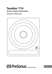
There are two display modes in the auxiliary window. When the distorsion button is pushed down, blue rectangle
and red center line corresponding to that of the main window are displayed. On the other hand, when the frame line
button is pushed down, frame lines and wire frame of the 3D model, if any, are displayed.
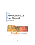
stretcher button
distorsion button
frame line button
correct button
text window
Stretcher and lens distorsion correction
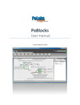
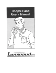
Strecher has an exaggerating effect of lens distorsion. Suppose there is an image with a slight lens distorsion.
Choose a line in the image, and place the stretcher's region indicator (blue rectangle) along the line.(Figure A) The
corresponding image in the auxiliary window shows the region with exaggerated distorsion.(Figure B) A line which
is slightly curved in the main window is displayed with so much curvature that the distorsion is easily visible.
The amount of lens distorsion can be expressed by a parameter called distorsion coefficient. Our task is to
estimate the value of this distorsion coefficient, and to correct the image according to the estimated value of
distorsion coefficient.
Estimation of distorsion coefficient
Enter an arbitrary value of distorsion coefficient (such as 0.1 for example) in the text window, then the red center
8
line gets distorted as shown in Figure C. Regulate the value so that the curved red line fits the target line in the
image.
Figure A
Figure B
Figure C
Figure D
Correction of the image
After you get a appropriate estimation value of the coefficient in the text window, push the correction button. The
background image is corrected so that the red curve gets straight. The corresponding image in the auxiliary window
also gets corrected as shown in Figure D.
The corrected image is saved when you save the model, and automatically loaded with the model when you load
the model next time.
8.4 Concurrence window
See section 3.Calibration --- Determining by choosing more than two lines
Last modified: Dec. 13. 1997
9