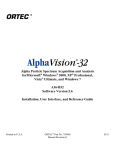
1
Scientific Production Company “Doza” ALPHA-BETA RADIOMETER UMF-2000 FOR LOW LEVEL ACTIVITY MEASUREMENTS User manual FVKM.412121.001RE Cont ent 1 Description and operation of the product ……………………….…….. 1.1 Product functionality …………………………………..….…… 1.2 Technical characteristics ……………………………..………… 1.3 Design and operation …………………...……………………… 1.4 Marking and sealing …………………………….…...………… 1.5 Packing ………………………………………………………… 2 Intended use …………………………………………………………… 2.1 Operational limitations ………………………………………… 2.2 Preparation of the product for use ...…………………………… 2.3 Use of a product …….….….…………………………………… 3 Maintenance ………………………………..…………………………. 3.1 General notes ………………………..…………………………. 3.2 Safety precautions …………………..…………………………. 3.3 Maintenance routine ….……..……….…………..…………….. 4 Calibration routine ……………….……….…………………...……… 4.1 General requirements ………..……….…………..……………. 4.2 Calibration procedure during putting into operation ……..……. 4.3 Calibration procedure during operation ………………….……. 5 Routine repairs …………………………………………..….………… 6 Storage ……………………………………………………….….……. 7 Transportation ………………………………………………..…….…. 8 Utilization ……………………………………………………...……… 3 3 3 4 6 6 6 6 6 7 9 9 9 9 9 9 9 13 15 15 15 16 Appendix A Block diagram of the radiometer ………………...……… Appendix B Wiring diagram ……………………………………..…… Appendix C Connection layout …………………………………..…… Appendix D Outline drawing …………………………………………. Appendix E UMF-PC interface …………………………..…………… 17 18 19 20 21 FVKM.412121.001RE 2 This User Manual contains information on design, principle of operation, characteristics of the product and instructions essential for correct and safe use of this product (intended use, maintenance, servicing, storage and transportation), as well as information regarding the utilization of the product. 1 DESCRIPTION AND OPERATION OF THE PRODUCT 1.1 Product functionality The alpha-beta radiometer UMF-2000 for low level activity measurements FVKM.412121.001 (hereinafter - radiometer) is intended for measurement of: - total activity of alpha and beta emitting nuclides contained in counting samples of foodstuff, soil and water, collected on air filters and in sorbents, as well as for measuring the activity of nuclides in the samples obtained by selective radiochemical extraction; - total activity of alpha emitting nuclides in “thick” and “thin” counting samples of environmental samples. The radiometer is used in laboratories for monitoring of water bodies. 1.2 Technical characteristics 1.2.1 Energy range of measured alpha radiation ……………….…………… 3500 to 8000 keV. 1.2.2 Energy range of measured beta radiation ………………...……………… 50 to 3500 keV. 1.2.3 Activity measurement range: - alpha radiation ………………….……………………….…….……….….… 0.01 to 103 Bq; - beta radiation …………………...………………….……….………….…… 0.1 to 3·103 Bq. 1.2.4 Limits of the permissible basic relative measurement error ……………………… ±15 %. 1.2.5 Radiometer maintains operability under the influence of the external background gamma radiation with energy of 662 keV and absorbed dose rate 0.50 μGy/h; under these conditions the limit of complementary measurement error is ………………..….………………………..……..…… 15 %. 1.2.6 Background count rate: - detectors with area 450 and 1000 mm2 in the alpha measurement channel ……………….…………..…… not more than 0.001 cps; - detectors with area 450 mm2 in the beta measurement channel ………………….…………..…… not more than 0.03 cps; - detectors with area 1000 mm2 in the beta measurement channel ………………………………...… not more than 0.07 cps. 1.2.7 Contribution of alpha channel into count rate of beta channel for thin alpha source …………………………………………………………..… not more than ±0.8 %. 1.2.8 Warm-up time under stable external conditions, not more than …………...……… 5 min. 1.2.9 Continuous operation during …….….………………….…….….……………… 24 hours. 1.2.10 Instability of readings during 8 hours of continuous operation relative to average value of readings for this period of time ……………………….………………………….…….……… ±5 %. 1.2.11 Power supply of the radiometer is provided from single-phase AC mains with voltage 22 220 33 V, frequency 50 11 Hz. Limits of complementary measurement error due to deviation of voltage or frequency from their values specified for normal operating conditions ……………………………………………±5 %. 1.2.13 Power consumption …………………………..….…….….……… not more than 40 VA. 1.2.14 Operating conditions: - operating temperature range: ……...….….……………….…….....….. minus 10 to + 35C; - maximum limit of relative humidity …………….….……….….…………. 75 % at +30C; - atmospheric pressure ………………………………………………….… 84.0 to 106.7 kPa; - content of the corrosive agents in the ambient air corresponds to the values in Table 1.1. FVKM.412121.001RE 3 Table 1.1 Type of atmosphere Designation I Designation Relatively clean Content of the corrosive agents Sulfur dioxide gas not more than 20 mg/(m2·day) (not more than 0.025 mg/m3); Chlorides not more than 0.3 mg/(m2·day) 1.2.15 Limits of complementary measurement error due to deviation of temperature from normal value to the limits of range of operating conditions ………………………………………±5 %. 1.2.16 During operation the radiometer shall not be subjected to vibration, shocks and other mechanical impacts. 1.2.17 Degree of protection against ingress of solid items and water provided by radiometer’s casings: IP23. 1.2.18 Radiometer is stable against electromagnetic interference of 2 grade according to the IEC 1000-4-8-93, IEC 61000-4-2-95, IEC 61000-4-3:2006, IEC 61000-4-4:2004, IEC 61000-4-5-95, IEC 61000-4-6-96, IEC 61000-4-11:2004. 1.2.19 Radiometer complies with the emission standards stated by the CISPR 16-1-93, CISPR 16-2-96 for equipment of class A. 1.2.20 By its protection against electric shock radiometer complies with the IEC 61010-1:2001. 1.2.21 Radiometer is a fire-safe product with fire probability of not more than 10-6 year-1. 1.2.22 Radiometer withstands the exposure to 5% citric acid solution in the rectified ethyl alcohol C2H5OH (density 96 %). 1.2.23 Overall dimensions …………….…………………………………… 321286190 mm. 1.2.24 Weight …………………………………………………………… not more than 21.6 kg. 1.2.25 Mean time to failure ……………...……….………….…..….. not less than 10000 hours. 1.2.26 Mean life time ………………………………………...…………… not less than 5 years. 1.3 Design and operation 1.3.1 The radiometer is assembled in a single case and consists of: - detecting device; - controlling part; - active cosmic ray shielding; - electronic parts; - two-channel counting device with timer. Block diagram of the radiometer is given in Appendix A. The radiometer’s front panel accommodates buttons “START” and “STOP” of the counting device, indicators, counting mode switch accounts and two LEDs, one indicates that the power supply is on and the other one – that the counting process is under way. The radiometer’s rear panel accommodates protective terminal strip, power switch, connectors “EXIT” and “RS-232”. Electric circuit, wiring diagram, overall and fitting dimensions of the radiometer are presented in the Appendices B, C, and D. 1.3.2 The detecting device contains: - semiconductor detector of high-resistivity Al-doped silicon, the size of 2020 mm (or 3232 mm), in a mandrel of chromium-plated brass; - counting sample holder with a device for advancing them to a fixed position near the detector. FVKM.412121.001RE 4 1.3.2.1 The semiconductor detector converts the energy of alpha and beta particles into electrical pulses by means of charge-sensitive preamplifier. The detector detects beta particles in the range of energies starting from 50 keV. It works as a transmission detector; it means that there is no information about the passed particle energy. When registering alpha particles, the detector is capable of providing spectrometric signal. Connection between detector and preamplifier is provided using the “LEMO” connector built into the detector’s mandrel. The drum has four fixed positions for measurement, which can be identified by a light blocking the drum as it rotates 1.3.2.2 The counting sample holder has four seats to accommodate plates with counting samples with the outer diameter of 45 mm. The drum has four fixed positions for measurement, which can be identified by a slight blocking of the drum as it revolves. To accommodate a counting sample in a fixed position relative to the detector it is necessary to rotate the drum to the next position. The radiometer with a detector area 1000 mm2 comes with a drawer-type counting sample holder. Before measurement one need to pull the holder, place a plate with counting sample and then push the holder in place to the extreme position. WARNING! The space is provided in the radiometer for measurement of samples on thick plates. The same place is used for calibration of the radiometer with the use of filters. The place for thick plates is 1 mm deeper than the standard locations for counting samples and marked. The radiometer with a detector area 1000 mm2 the place for a check source is located on the bottom surface of the insert for counting samples. To install the check source, turn the insert upside-down. 1.3.3 The controlling part includes a power supply module and module of conditioners, which serves to separate the pulses from alpha and beta particles and has an anticoincidence circuit, high voltage module for HV supply to active shielding and protection against power line disturbances. The power supply module is used to convert the AC voltage 220 V to +12 V, -12 V and 5 V DC for electronic devices. In addition, the power supply module generates bias voltage for the detector. 1.3.4 The active cosmic ray shielding includes gas-discharge counter, located under the counting samples holder. The active shielding is used to reduce the contribution of high-energy cosmic rays to the detector’s background. When a charged particle hits the detector, a signal in the form of a voltage pulse from the detector is delayed and transmitted to the counting circuit only if within the waiting time a pulse is not received from the active shielding system, or from the system of protection against power line disturbances. Otherwise, the pulse from the detector is ignored. 1.3.5 The electronic part is designed as separate blocks: preamplifier, conditioners, power supply, counting device controller board with timer, and two indicator boards. 1.3.5.1 The preamplifier is designed by the “classical” resistive circuit; due to low detector’s inverse currents allows having a noise at a level of 5…15 keV. Pre-amplified signal is transferred to the input of the main amplifier, which uses a high-speed operational amplifier. The main amplifier provides output signal amplitude for beta particles at the level of 20 mV to 1 V. The amplified signal is fed to the input of the selection circuit in the electronic part, made with integrated comparators. Comparator thresholds are set so that the first comparator is triggered by both alpha and beta particles pulses, and the second one is triggered only by alpha particles pulses. The signals from comparators are fed to the anticoincidence circuit, which permits counting of beta particles only (beta-channel). For the alpha particles counting only the signal of the second comparator is taken into account. The electronic part also accommodates the anticoincidence circuit for systems of active shielding and protection against power line disturbances. 1.3.5.2 The electronic part also includes a pulse power supply module and a high voltage module. FVKM.412121.001RE 5 1.3.6 The two-channel counting device with timer consists of three counting paths with fourdigit indicators and an electronic timer. The duration of measurement is determined by time selector (four digital switches). Pushbutton switches located on the front panel allow to start the measurement with simultaneous reset of the previous result, and to stop the measurement at any time. 1.3.6.1 The counting scheme is built with the use of a microprocessor; information is displayed on seven-segment LEDs and has two channels. 1.3.6.2 Pulses corresponding to alpha particles are counted in the first channel; the second channel is used for counting of pulses from the beta particles. The indication mode can be changed using buttons “α, β” and “β, TIME”. In the “α, β” mode the indicator displays alpha and beta counts, while in the “β, TIME” mode it is beta counts and elapsed time. The indication mode does not affect the operation of the radiometer. 1.3.6.3 In the case of an overflow in one of the channels counting stops and the central segments are lit at the indicator corresponding to the overflowed channel. At that it is possible to view the content of other channels. Stopping of counting is accompanied by an audible signal. To turn the signal off press the “STOP” button or start a new measurement. 1.4 Marking and sealing 1.4.1 The following information is presented on the radiometer: - trademark and name of the manufacturer (supplier); - reference designation of the radiometer; - works number of a radiometer according to the manufacturer's system of numeration; - degree of ingress protection against solid items and water provided by casings; - voltage, power consumption or current, power supply frequency. 1.4.2 Location and method of marking of the radiometer correspond to the design documentation. 1.4.3 The radiometer is sealed in accordance with the design documentation. 1.5 Packing 1.5.1 The radiometer’s package complies with the design documentation and provides protection against ingress of atmospheric precipitations and aerosols, splashes of water, dust, sand, solar ultra-violet radiation and limits the ingress of water vapour and gases. 2 INTENDED USE 2.1 Operational limitations 2.1.1 Radiometer retains operability under conditions stated in 1.2. 2.1.2 Using mobile phones is prohibits near the operating radiometer. WARNING! DO NOT USE RADIOMETER FOR PERFORMING MEASUREMENTS OF SAMPLES WITH HIGH CONTENT OF ACIDS OR ALKALI TO PREVENT DAMAGE TO THE WORKING SURFACE OF DETECTOR. 2.2 Preparation of the product for use 2.2.1 Before using the radiometer check that the power cord is connected correctly and not damaged, check grounding. After that connect the power cord to the wall outlet and turn the power switch located on the rear panel to the “POWER ON” position. At that time the red LED must light up located next to the marking “POWER” on the front panel. FVKM.412121.001RE 6 2.2.2 Immediately after turning the radiometer on it switches to the test mode, which facilitates performance testing. At that time the top indicator displays internal serial number of the radiometer, which is used to control it via RS-232, and the lower indicator displays elapsed time. Pressing and holding the mode selection button allows to displaying on the top indicator of the time interval set by time controller. By changing the settings of digital switches, while holding the button, the value of time set by these switches can be compared against the value, which will be used during real measurements. To activate the operating mode, press the “START” button. 2.2.3 The radiometer is capable to operate under external control using RS-232 interface; the RS-232 connector is located on the rear panel. To switch to the external control mode, set the digital switches of the time controller to 0000 before switching the radiometer on. After that the radiometer will not respond to pressing buttons on the front panel. Commands for controlling the radiometer are listed in the Appendix D. 2.2.4 Using mode selection button select “α, β” or “β, TIME” mode. 2.2.5 Warm up the radiometer during 30 minutes. 2.2.6 Load an empty plate (previously wiped with a tissue moistened with alcohol) to the counting position and perform background measurement for at least 1000 seconds. Make sure that the background value is within the limits specified in the certificate of calibration. If you notice increase in the background, identify and fix the problem. 2.2.7 Place the check source (complete with radiometer) to the counting samples holder and perform measurement during 300 seconds. The obtained value of count rate should be within the limits specified in the certificate of calibration. WARNING! THE CHECK SOURCE SHALL BE PLACED INTO THE DEEPENING MARKED BY RED OR WHITE DOT OR INTO THE UPTURNED INSERT (FOR RADIOMETERS WITH DETECTOR WITH AREA 1000 MM2). 2.2.7 Proceed to routine measurements. 2.3 Use of a product 2.3.1 Operations needed to determine the activity of a counting sample include measurements of count rate with an empty plate (background) and with a counting sample on a plate. The measurements are carried out with drum in a fixed position. 2.3.2 During measurements you should use the value of background which is obtained as the average of 8…10 measurements, at that each of the background measurements should record at least 10 counts. Later on the purpose of background measurements should consist in demonstration of compliance of the current background value with the average one, taking into account the statistical spread. The statistical error of the background measurement is given by N bgr 1,96 N bgr , (2.1) where Nbgr is the number of background counts, 1.96 is the Student's coefficient at a confidence level 95 %. 2.3.3 Perform several measurements of a counting sample. The measurement result is expressed as counts registered by the radiometer in both channels during the time t. FVKM.412121.001RE 7 Determine the average count rate from counting sample (including the background) by the formula k Ni n i 1 k , (2.2) ti i 1 where N i is the number of counts, obtained in i-th measurement; t i is the i-th measurement interval. 2.3.4 Determine the average count rate from counting sample n сч excluding background n sample n n bgr , (2.3) where n bgr is the average count rate. Calculate the absolute error in the count rate n sample (cps) using the formula n sample 1.96 n t meas n bgr , t bgr (2.4) where t meas is the total measurement time of the sample; t bgr – is the total measurement time of the background. 2.3.5 The calculation according 2.3.3 and 2.3.4 shall be performed for each channel. 2.3.6 Calculate the activity A for the measured counting sample by the formula A n sample , (2.5) where is the sensitivity of the radiometer for measured type of radiation stated in the calibration certificate of the radiometer. Calculate the relative error of measured activity A , in percentage terms, according to the formula 2 n sample A 1.1 100 () 2 , n sample (2.6) where is the relative error of sensitivity stated in the calibration certificate, %. 2.3.7 Record the activity A (Bq) of the measured counting sample, taking into account the errors, in a form А А А 100 (2.7) 2.4 When working with radiometer it is recommended to use “Methods for measuring the total alpha and beta activity of water samples (fresh natural waters for household use) after concentration using alpha-beta radiometer UMF-2000” and guidelines “Gross activity of alpha and beta emitting radionuclides in natural (fresh and mineral) waters. Sample preparation and performing measurement”. 2.5 Optional spectrometric ADC, signal cable, software “Spdec” and radiochemical methods of selective electrochemical deposition allows using the radiometer for activity measurements of corresponding alpha and beta emitting radionuclides. FVKM.412121.001RE 8 3 MAINTENANCE 3.1 General notes Maintenance is performed with the purpose of ensuring reliable, long-term operation of radiometer. The following types and timing of maintenance work are recommended: - Visual inspection ……………………………..…..………………..……. every month; - External cleaning ……………………………………….………………... every month; - Testing of main parameters ………………………………………...……. every year. 3.2 Safety precautions 3.2.1 Before beginning to work with radiometer familiarize yourself with this User Manual. 3.2.2 During all operations with detectors follow occupational and radiation safety requirements of current safety instructions in the company (enterprise). 3.2.3 The radiometer should be reliably grounded through the ground terminal on the rear panel during operation. 3.2.4 The voltage 400 V is produced in the high voltage module for supply of the active shielding system; do not open the radiometer case earlier than 10 minutes after it is turned off. The power supply voltage 220 V is present in the radiometer; therefore it is prohibited to connect it to the electrical network when the cover is removed. 3.3 Maintenance routine Maintenance is divided into routine and periodic. 3.3.1 Routine maintenance 3.3.1.1 Routine maintenance is carried out during regular operation; it includes inspections of radiometer for timely detection and elimination of factors which can compromise their operability and safety. If any warping or damages are found immediately eliminate them to avoid the failure of the radiometer. 3.3.2 Periodic maintenance Periodic maintenance consists of calibration and decontamination of the radiometer. 3.3.3 Deactivation of the radiometer is carried out in accordance with current decontamination regulations of enterprise (facility), as well as after increasing of the radiometer’s background above the permissible level. The drum (drawer) for sample plates shall be decontaminated and, if necessary, the external surfaces of the radiometer; decontamination solutions shall be used in accordance with 1.2.21. 4 CALIBRATION ROUTINE 4.1 General requirements 4.1.1 Calibration of radiometer shall be carried out in accordance with the requirements of IEC 61453:2007. 4.2 Calibration procedure for putting into operation The calibration procedure for putting the radiometer into operation and relevant metrological characteristics shall be based on the user’s specific measurement tasks. The following parameters are to be determined and recorded in the calibration certificate during primary calibration of each radiometer: detection efficiency of alpha and beta particles (depending on counting samples weight), reference values of the count rate from check sources 90Sr and 239Pu for a fixed geometry of measurements, the values of background for alpha and beta channels. FVKM.412121.001RE 9 4.2.1 Calibration operation and equipment Operations performed during calibration and necessary equipment are listed in the Table 4.1. Table 4.1 – Calibration operations and calibration equipment Operation Section 1 External examination 2 Testing 3 Determination of sensitivity of the radiometer 4.2.4.1 4 Determination of basic relative error of activity measurement 4.2.4.4 4.2.4.2 4.2.4.3 Calibration equipment and its technical characteristics Visual Working standards: - special purpose sources 137Cs with thickness 0.02…0.06 g/cm2 (at least three sources with different thickness), activity 50…200 Bq, uncertainty not more than ±9 %; - special purpose sources 90Sr (90Y) with thickness 0.02…0.06 g/cm2 (at least three sources with different thickness), activity 50…200 Bq, uncertainty not more than ±9 %; - thin source 239Pu on the plate, with self-absorption not more than 15 keV, activity 1…50 Bq, uncertainty not more than ±5 %. - Working standard (grade 2) based on granulated source 239Pu, specific activity 10…50 Bq/g, uncertainty not more than ±10 %. - Working standard (grade 2) based on granulated source 40K, specific activity 10…50 Bq/g, uncertainty not more than ±10 %. - Check source OISN-238 (238U +234U) with activity 20…200 Bq, complete with radiometer. - Stopwatch, tweezers. Working standards: - special purpose source 137Cs with thickness 0.02…0.06 g/cm2 , activity 50…200 Bq, uncertainty not more than ±9 %; - thin source 239Pu on the plate, with self-absorption not more than 15 keV, activity 1…50 Bq, uncertainty not more than ±5 %. - Check source OISN-238 (238U +234U) with activity 20…200 Bq, complete with radiometer. - Stopwatch, tweezers. N o t e - It is allowed to use other tools and equipment with similar characteristics ensuring determination of metrological characteristics of radiometer with required precision. 4.2.2 Safety precautions During calibration follow safety requirements described in section 3.2 and in documentation accompanying calibration tools and equipment. 4.2.3 Conditions for calibration and preparation for calibration The following normal operating conditions shall be met during calibration: - air temperature …………………………………………..….…………………. +(20 ±5) °C; - relative air humidity ……….………………………….......……..……...… from 30 to 80 %; - atmospheric pressure ……………………………………….………….… 86.0 to 106.7 kPa. - natural radiation background ………………..……………...…… not more than 0.2 μSv·h-1. In the process of calibration the possiblility should be excluded of the external radiation background increasing due to extraneous radioactive sources. FVKM.412121.001RE 10 4.2.4 Performing calibration 4.2.4.1 External examination Items to be checked during external examination: - Proper completeness; - Absence of defects which could affect the radiometer’s operation; - Availability of operational documentation. 4.2.4.2 Testing Testing of radiometer includes turning it on, determination of operability of LEDs and digital indicators, testing “START” and “STOP” buttons and operation of timer. To test the timer, select “β, TIME” mode, set measurement interval equal to 1 s and press “START”. Watch indication of time (in seconds) on the lower digital indicator. Note that the measurement stops after 1 second. Repeat the last step with the measurement interval settings 10, 100 and 1000 seconds. 4.2.4.3 Determination of the radiometer’s sensitivity: 1) using granulated sources 239Pu and 40K prepare weighted portions on plates for measuring in accordance with the Table 4.2; Table 4.2 – Samples (weighted portions) for calibration Weighted portions 239Pu Weighted portions 40K radiometer with detector 450 mm2 20 mg 50 mg 100 mg 200 mg 100 mg 300 mg radiometer with detector 1000 mm2 100 mg 200 mg 400 mg 600 mg 100 mg 200 mg 400 mg - 2) after warm-up and reaching operation condition of the radiometer, perform background measurements simultaneously in the alpha and beta channels with measurement interval 3000 s, at least 5 times, background measurements shall be carried out with empty plate in the counting position of the detecting module. Calculate the average background count rate in channels nbgr by the formula k N ibgr n bgr i 1 k , (4.1) t ibgr i 1 where N ibgr is the number of counts, obtained in i-th background measurement, t iф is the i-th measurement interval, k is the number of background measurements; 3) measure the count rate for the working standards 40K, 239Pu, 137Cs and 90Sr(90Y), measurement interval shall be large enough to ensure registration of at least 1000 counts in two channels simultaneously, and at least five times; FVKM.412121.001RE 11 4) calculate the average count rate n for each sample by the formula k Ni n i 1 k , (4.2) ti i 1 where N i – number of counts, obtained in i-th measurement, t i – i-th measurement interval, k – number of measurements of the sample, record the obtained results in the calibration report (of any from); 5) calculate the average count rate n сч excluding background and its statistical uncertainty S n sample in absolute values for each nuclide and sample mass, respectively, by the formulas (4.3) n cal n n bgr S n cal n t sample n bgr , t bgr (4.4) where t sample is the total measurement time of the sample, s, t bgr is the total measurement time of background, s; 6) calculate the sensitivity of the radiometer for 40K, 239Pu, 137Cs and 90Sr(90Y) by the formula (4.5) for each value of the weight of the source (weighted portion), source weights for 137Cs and 90Sr(90Y) are stated in certificate of calibration n cal AS (4.5) where AS is the activity of the working standard, calculated by the formula A S А pasp e 0.693 t / T1 / 2 , (4.6) where А pasp is the activity of the working standard from the certificate of calibration, t is the period of time elapsed since the time of source calibration, years, T1/2 is the half-life of the radionuclide, years, A и is the working standard uncertainty, %; 7) calculate the uncertainty of sensitivity , in percentage terms, by the formula 2 1.96 S n cal 2 100 A S , n cal (4.7) where 1.96 is the Student's coefficient at a confidence level 95 %. AS is the uncertainty of the working standard, %. Recorded the values of and in the certificate of calibration. 4.2.4.4 Determination of the basic relative error of activity measurements: 1) perform activity measurement with any 137Cs source and with thin accordance with the procedure set out in 2.3; FVKM.412121.001RE 12 239 Pu source in 2) determine the error of radionuclide activity measurement A in percentage terms, by the formula 2 A AS 2 A 1,1 100 , AS (4.8) where A is the value of activity determined in accordance with the method set out in 2.3, Bq, А S is the activity of the working standard from the certificate of calibration, Bq, is the uncertainty of sensitivity for particular radionuclide. The obtained results should be in the range stated in 1.2.4; 3) measure the value of the count rate from the check source and record it in the certificate of calibration. 4.3 Calibration procedure during operation This procedure applies to radiometers in operation and establishes methods and means of calibration. 4.3.1 Calibration operation and equipment Operations performed during calibration and necessary equipment are listed in the Table 4.3. Table 4.3 – Calibration operations and calibration equipment Operation Section 1 External examination 2 Testing 3 Determination of basic relative error of activity measurement 4.3.4.1 4 Processing of measurement results 4.3.4.4 4.3.4.2 4.3.4.3 Calibration equipment and its technical characteristics Visual Working standards: - special purpose source 137Cs with thickness 0.02…0.06 g/cm2 , activity 50…200 Bq, uncertainty not more than ±9 %; - thin source 239Pu on the plate, with self-absorption not more than 15 keV, activity 1…50 Bq, uncertainty not more than ±5 %. - Check source OISN-238 (238U +234U) with activity 20…200 Bq, complete with radiometer. - Stopwatch, tweezers. N o t e - It is allowed to use other tools and equipment with similar characteristics ensuring determination of metrological characteristics of radiometer with required precision. 4.3.2 Safety precautions During calibration follow safety requirements described in section 3.2 and in documentation accompanying calibration tools and equipment. 4.3.3 Conditions for calibration and preparation for calibration The following normal operating conditions shall be met during calibration: - air temperature …………………………………………….……….…………. +(20 ±5) °C; - relative air humidity ……….………………………….....……..….…...… from 30 to 80 %; - atmospheric pressure ………………………………………………….… 86.0 to 106.7 kPa; - natural radiation background ……………..…..………………… not more than 0.2 μSv·h-1. FVKM.412121.001RE 13 In the process of calibration the possiblility should be excluded of the external radiation background increasing due to extraneous radioactive sources. 4.3.4 Performing calibration 4.3.4.1 External examination Items to be checked during external examination: - Proper completeness; - Presence of seals; - Absence of defects which could affect the radiometer’s operation; - Availability of operational documentation. 4.3.4.2 Testing Testing of radiometer includes turning it on, determination of operability of LEDs and digital indicators, testing “START” and “STOP” buttons and operation of timer. To test the timer, select “β, TIME” mode, set measurement interval equal to 1 s and press “START”. Watch indication of time (in seconds) on the lower digital indicator. Note that the measurement stops after 1 second. Repeat the last step with the measurement interval settings 10, 100 and 1000 seconds. 4.3.4.3 Determination of the basic relative error of activity measurements: 1) after warm-up and reaching operation condition of the radiometer, perform background measurements simultaneously in the alpha and beta channels with measurement interval 3000 s, at least 5 times, background measurements shall be carried out with empty plate in the counting position of the detecting module; 2) calculate the average background count rate in channels n bgr by the formula k N ibgr n bgr i 1 k , (4.9) t ibgr i 1 where N ibgr is the number of counts, obtained in i-th background measurement, t iф is the i-th measurement interval, k is the number of background measurements; 3) perform measurement of count rate with 137Cs source and thin 239Pu source with the purpose of determination of activity measurement error; 4) determine the average count rate from counting sample n , including background k Ni n i 1 k , (4.10) ti i 1 where N i – number of counts, obtained in i-th measurement, t i – i-th measurement interval; 5) determine the average count rate from counting sample n сч excluding background n sample n n bgr (4.11) 6) perform measurement of count rate with combined check source complete with radiometer. 4.3.4.4 Processing of measurement results Calculate the uncertainty of determining the activity of radionuclides in counting samples. With this purpose determine the measured activity values А of working standards 137Cs and 239 Pu by the formula FVKM.412121.001RE 14 n sample (4.12) where is the radiometer’s sensitivity for a given source (radionuclide), determined at the phase of putting radiometer into operation and stated in the certificate of calibration. A Determine the error of radionuclide activity measurement A in percentage terms, by the formula 2 A A0 2 A 1.1 100 , A0 (4.13) where А 0 is the activity of the working standard stated in the certificate of calibration, Bq; is the uncertainty of sensitivity for particular radionuclide, %. The obtained result should not exceed the value stated in 1.2.4. 5 ROUTINE REPAIRS 5.1 Modules of the radiometer are not repairable and in the case of a failure should be replaced at the factory of manufacturer. 6 STORAGE 6.1 Prior to putting into operation radiometer shall be stored in a heated warehouse with natural ventilation: - in manufacturer’s package – at ambient temperatures from +5 to +40 C and relative humidity up to 80 % at +25C; - unpacked – at ambient temperatures from +10 to +35 C and relative humidity up to 80 % at +25 C. 6.2 The storage location should be free of dust, chemical vapours, aggressive gases and other substances that may cause corrosion. The storage location shall exclude exposure of radiometers to the direct rays of sunlight. 7 TRANSPORTATION 7.1 Radiometer in the original manufacturer’s package can be transported by all means of transport at any distance: - transportation by railway shall be carried out in clean boxcars; - when transported by open motor transport boxes shall be covered by the water-proof material; - when transported by air the boxes with radiometers shall be placed in air-tight heated compartment; - when transported by water and sea transport the boxes with radiometers shall be placed in the hold. 7.2 Arrangement and fastening of the boxes on transport means shall provide their steady position en route, absence of displacement and striking each other. 7.3 The requirements of the inscriptions on the transport packing shall be observed during loading and unloading. During loading and unloading radiometer should not be exposed to precipitation. FVKM.412121.001RE 15 7.4 Transportation conditions are as follows: - temperature …………………………………………………..….. from minus 30 to +50 °C; provided gradual temperature stabilization is ensured during unloading at temperatures from -10 to +35 °C and subsequent storage under the normal conditions during 24 hours; - humidity …………………………………….………………....…..… up to 95 % at +35 °C; - impact of shaking with an acceleration 30 m/s2 at a frequency of 10…120 shocks/min. 8 UTILIZATION 8.1 On full expiry of the service life of radiometer (or its parts) and also prior to its dispatching for repair or calibration it shall be inspected for possible radioactive contamination of its surfaces. Criteria for decision making on decontamination and further use shall comply with obligatory requirements of national standards. 8.2 Decontamination shall be attempted in cases when the contamination of radiometer’s surfaces (including surfaces accessible during repair) can be reduced below allowable limits. In case the radioactive contamination exceeds allowable limits, requirements set forth for the radioactive wastes become applicable to the detectors. 8.3 Radiometer accepted for operation after decontamination shall be repaired or replaced in case of failure. Radiometer which is not suitable for operation, with radioactive contamination levels below permissible limits, should be dismantled to preclude its further use and transferred to a special site for disposal of industrial wastes. 8.4 Radiometer with expired lifetime, accepted for use after decontamination, shall undergo technical inspection. If the technical condition of a radiometer is satisfactory, an extended operation term of the product shall be determined. FVKM.412121.001RE 16 Appendix A (Obligatory) BLOCK DIAGRAM OF THE RADIOMETER STOP where 1 – counting sample holder; 2 –counting sample; 3 – detection device; 4 – active shield; 5 – preamplifiers; 6 – discriminators; 7 – anticoincidence circuit; 8 – timer; 9 – power supply unit; 10 – high voltage unit; 11 – indicators. FVKM.412121.001RE 17 START FVKM.412121.001RE 18 WIRING DIAGRAM Appendix B (Obligatory) Appendix C (Obligatory) CONNECTION LAYOUT FVKM.412121.001RE 19 FVKM.412121.001RE 20 OUTLINE DRAWING Appendix D (Obligatory) Appendix E (obligatory) INTERFACE UMF-PC E.1 When the radiometer is turned on with preset non-zero measurement interval, it switches to manual mode. In this case: - radiometer execute all commands which result in a transfer to a PC of certain parameters; commands that change current state of the radiometer are blocked (a command is received, processed, but the prescribed actions are not performed; the returned status byte contains information about the state of the radiometer at the moment when operation is complete); - “START” and “STOP” button are operable; - in the test mode, immediately after the radiometer is turned on, the upper indicator displays the serial number of current turning on (in the “N.xxx” format). When buttons “α, β” or “β, TIME” are pressed and hold, instead of radiometer’s number a value read from the digital switches (time setting) is displayed. The lower indicator displays seconds since the turning on of the radiometer. The “STOP” button in this mode generates an audible signal. The “START” button starts measurement. E.2 After normal completion of acquisition (elapsed time equals to the preset time) counting (measurement) stops, the LED “MEASUREMENT” goes out, and an intermittent beep is heard, which can be switched off by the “STOP” button. If counting is stopped as a result of pressing the “STOP” button or manipulations with timer, when elapsed time exceeds the newly set value, than the lower indicator alternately shows timer value and counting channel value. Next measurement cycle can be started by pressing the “START” button; measurement data are automatically reset simultaneously. When the radiometer is turned on with zero time (set by digital switches), it is in the PC control mode. Not e - Subsequent manipulations with digital switches will not switch the radiometer to manual mode. In this mode “START” and “STOP” button are blocked. The radiometer executes all commands from the PC. In test mode, pressing the “START” button resets the timer readings displayed on the lower indicator. When the radiometer is restarted to the next measuring cycle, the acquired data will not reset. E.3 Data via serial port are transferred at the speed of 19200 baud using the RS-232 interface. The parcel is only accepted if: - at least 10 ms have passed since the receipt of the last byte (any byte transferred from the central PC to any radiometer); - the first byte in the parcel is equal to the radiometer number (1 - 255) or is an interrogation byte (0). The radiometer reads a specified number of bytes (defined by number of commands transmitted in the second byte of the parcel). If transmission error is detected (next byte has expired or checksum does not match) the radiometer generates a message: <0BBh>. Note - byte is considered expired if it is delayed relative to the previous one for more than 10 ms. After receiving and analyzing a parcel the radiometer executes the command set (if enabled) and generates a confirmation message. The functions realized in previous models of radiometer, which are not mentioned in this text, remained unchanged. FVKM.412121.001RE 21 Table E.1 - The structure of the control byte Bit number 0 1 2 3 4 5 6 7 Bit is equal to zero radiometer is idle radiometer is in test mode radiometer is manually controlled Bit is equal to 1 radiometer is working radiometer is in working mode overflow of channel 0 overflow of channel 1 data from channel 0 are already read data from channel 1 are already read radiometer is controlled from PC EEPROM read error * * WARNING! If during reading of the next byte from EEPROM an error occurs, then the total duration of attempts (per byte!!) will be approximately 100 ms, as a result the period between transfer of bytes of a parcel can vary and fall in the ranges from 0.1 ms to 100 ms. The total response time can reach 2.5 seconds. FVKM.412121.001RE 22 Table E.2 - List of commands executed by the radiometer Command number Function Parcel PC-UMF 00h 01h 02h 03h 04h 05h RESERVE Report current status of the radiometer Report elapsed counting time Report set counting time Report data for channel 0 Report data for channel 1 <№><01h><КС> <№><02h><КС> <№><03h><КС> <№><04h><КС> <№><05h><КС> 06h Report ALL data <№><06h><КС> Report byte from memory bank PAGE at address ADR. Set new counting time Report bank (256 bytes) No. PAGE Write a byte in EEPROM into memory bank PAGE at address ADR Reset of ALL data (channels and time) Reset of preset time Stop counting Start counting RESERVE <№><07h><PAGE><ADR> <КС> <№><08h><HItf><LOtf><КС> 07h 08h 09h 0Ah 0Bh 0Ch 0Dh 0Eh 0Fh <№><07h><PAGE><КС> <№><0Fh><PAGE><ADR> <DAT><КС> <№><0Bh><КС> <№><0Ch><КС> <№><0Dh><КС> <№><0Eh><КС> FVKM.412121.001RE 25 Parcel UMF-PC <№><01h><БС><КС> <№><02h><HItf><LOtf><БС><КС> <№><03h><HIt><LOt><БС><КС> <№><04h><HI0><LO0><БС><КС> <№><05h><HI1><LO1><БС><КС> <№><06h><HItf><LOtf><HIt><LOt> <HI0><LO0><HI1><LO1><БС><КС> <№><07h><DAT><БС><КС> <№><08h><БС><КС> <№><09h><DAT0><DAT1> <DAT255><БС><КС> <№><0Fh><БС><КС> <№><0Bh><БС><КС> <№><0Ch><БС><КС> <№><0Dh><БС><КС> <№><0Eh><БС><КС>