1
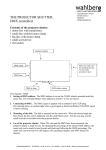
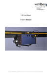
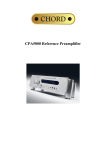
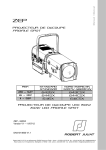
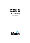
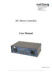
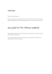
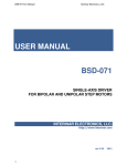
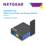
Jægergårdsgade 152/05A DK-8000 Aarhus C DENMARK WWW.WAHLBERG.DK 220 Winch 25 Users Manual WWW.WAHLBERG.DK · TELEPHONE +45 86 18 14 20 · CELL PHONE +45 40 52 20 88 · EMAIL: [email protected] Index: GENERAL PRODUCT CONTENT DESCRIPTION AREA OF USE WINCH 25 FEATURES CONNECTING THE WINCH ADJUSTING THE LIMIT SWITCHES MENU LIFTING CAPACITY AND REQUIRED SETTINGS CONTINUOUS USE LED FUNCTIONS ERRORS AND ERROR CODES: POWER FAILURE INSPECTIONS AND MAINTENANCE MAINTENANCE PLAN ROLLING UP THE WIRE CHEAT SHEET - WINCH 25 805.220.001 4 4 4 4 6 7 8 10 11 11 13 13 13 14 14 15 16 2 TECHNICAL SPECIFICATIONS: Item No. Dimensions Power supply Power consumption Power plug DMX Control signal DMX connection Lifting height Lifting capacity Lifting speed Lifting cable Min. Load Ambient temperature Duty cycle Noise emission Weight Mounting clamp Motor 805.220.001 : 220 : 400 x 225 x 290 mm / 15.74 x 8.86 x 11.42 in (Height-Width-Depth) : 230 volt AC 50 - 60Hz. : Max 300 Watt. : Neutrik powerCON male : DMX 512 1990 + DMX 512A / 6 Channels used : 5 pole XLR, In & link : 10 m. (33 ft.) : 25 kg. (55 lbs.) : Variable 5-70cm/s (2-27in/s) : 2mm galvanised steel wire, 8mm snap hook, MBL 281 kg (620 lbs.) : 1 kg. Lower weight can course wire winding problems. : 0-40 °C (32- 104 °F) : Max 30% at max load : ~50 dB : 21 kg. (46 lbs.) : Manfrotto MP Slim eye coupler C4560 (Max load: 300 kg) Half coupler 50 mm. (2 inch.) 0.26kg Two couplers separated by 200mm (7.88 in) : 230 V AC, 0.25 kW, IP55 3 General Before using the winch for the first time, please read the installation- safety- operation- and maintenance instructions carefully. Failure in handling can cause injury of persons and/or damage the winch. Product content 1 Winch 25 1 Powercon plug for cable 1 Emergency stop connection 1 Instruction manual Description The Winch25 is a wire winch for lifting and moving scene objects. The winch is controlled from the lighting desk, and thereby stage movements can be controlled in corporation with the lights, this will add dynamic to the performance or play. Winch25 has an advanced positioning system that is controlled with a 16 bit DMX channel. This gives a very high accuracy. The lifting speed is also controlled by DMX, and it is possible to limit the outer ranges of how high or low the winch can move. Winch 25 should only be operated by an experienced DMX-controlled-lighting-desk-operator. The lighting desk has to be programmed according to the manual, so the winch will stop when the speed is put to 0 %. It is also possible for the user to stop the winch on the main. After power failure the start position of the winch should be reset. The winch is for indoor use only! Area of use: The Winch is intended for indoor use. It is designed for lifting and lowering material at the weight and speed stated in "Technical Data". Any other use of the winch may result in a risk of injury of persons or equipment damage. Exceeding the load rating may cause failure of the equipment. Use only approved rigging connectors to secure the load to the wire and do not wrap the wire around the load as this will damage the wire and result in a risk of injury of persons or equipment damage. Do not modify the winch. Any modification you might need should be done by Wahlberg. It is the customers' responsibility that any local restrictions concerning the use of the winch are complied with. Caution: "To reduce the risk of electric shock or injury: Use Indoors Only." Caution: "To reduce the risk of electric shock, do not expose to rain: Store indoors." 805.220.001 4 Attention! Before running the winch read the user’s manual paying special attention to the chapter "Connecting the winch". It is important to keep the wire in a good condition. See "Maintenance". Make sure the operator is able to watch the winch while running it in order to have visual confirmation of the movements. The winch should only be operated by an experienced DMX-controlled-lighting-desk-operator. When running manually, the operator should make sure not to be placed in a hazardous situation. Likewise it is the operator's responsibility not to run the winch in a way that brings other persons in a hazardous situation. During set-up and each time before use, the safe condition of the winch must be established with a visual inspection and a functionality test. Pay special attention to the mounting of the winch and the condition of the wire! Cautions at power failure: The winch will stop at power failure. When the power is re-established, the winch has to be reset before it is ready to use. It is advisable to set all the DMX channels on 0 % before the power is re-established. Warning! Use of the winch for other than the intended purpose can cause injury! 805.220.001 5 Winch 25 Features The Winch25 is a wire winch for lifting and moving scene objects. The winch is controlled from the lighting desk, and thereby stage movements can be controlled in corporation with the lights, this will add dynamic to the performance or play. Winch25 has an advanced positioning system that is controlled with a 16 bit DMX channel. This gives a very high accuracy. The lifting speed is also controlled by DMX, and it is possible to limit the outer ranges of how high or low the winch can move. The positioning system has to be reset every time the power to the winch is turned back on. For resetting, use DMX channel 5. If one of the following 3 possibilities is fulfilled, the position will be saved in the build in memory, and therefore it will not have to be reset at the next power on. 1. The winch has been stopped for more than 30 seconds. 2. DMX speed (channel 3) has been set to 0 % or channel 4 is out of the 50-55 % area for more than 10 seconds. 3. The emergency switch has been pressed for more than 3 seconds. When the Winch25 is turned on the winch cannot run before DMX channel 4 has been out of the enable area of 50-55 %, after this the winch has to be reset again. Emergency switch: Before the Winch25 can run, it needs power on the emergency switch: 15 VDC between grounding pin 1 and pin 4. If the connection between 1 and 4 is lost the winch will stop, the red ERROR light will be on, and the display will show: EMERGENCY STOP PRESSED An emergency switch can be connected to this plug, between pin 1 and 4. Counterweight: It is very important to have at least 1Kg load on the wire before start running the winch. If no weight is applied in the wire, it will jam on the drum. DMX channels used for controlling the winch (For a more detailed description see page 9) DMX channel 1 – Position. (16 bit DMX channel) DMX channel 2 – Position fine. (16 bit DMX channel) DMX channel 3 – Maximum speed DMX channel 4 – Motor Enable – between 50 % and 55 %, to enable the motor output. DMX channel 5 – Reset UP DMX channel 6 – Manual DWN, (Sets the TAC RANGE) Resetting the up position: Run the motor to the top reset position, with channel 5. Setting DMX channel 5 to 0% resets the position 805.220.001 6 Connecting the Winch Power supply The Winch 25 must be connected to 230VAC, Power is connected to the blue Neutric Powercon connector. By supplying power to the winch, the display will show a start-up screen and then change to DMX CONTROL START CHAN 1 DMX DMX is connected to the male 5-pole XLR connector. The DMX LED will light constantly when receiving a DMX signal, and it will blink when no DMX are received. Emergency stop switch If the emergency stop switch is activated (pin 1 and pin 4 are disconnected) the red ERROR LED will light. The emergency stop switch is connected to the male 4 pole XLR connector. Pin 1 and Pin 4 should be powered with 12-15 volt DC to enable the running of the motor Pin out: Pin 1 = GND Pin 2 = NC Pin 3 = NC Pin 4 = 12 – 15 volt DC Emergency stop input Emergency stop input Ready to use When the winch has been connected to 230VAC, a DMX light desk, and an emergency stop switch, it is ready for use, and can be controlled from the light desk. 805.220.001 7 Adjusting the limit switches To adjust the limits first remove the black cover, it is attached with two screws. The limit switch determines the maximum and minimum travel distance of the winch. To adjust the limit switch loosen the middle screw. Then the top and bottom limits can be adjusted with the two screws. The limits are adjusted by rotating the white levers using the screws for top and bottom limit. While adjusting the limits put the winch in manual mode. The winch will write out LIMIT TOP ACT when it hits the top limit while moving up and LIMIT BOTTOM when it hits the bottom limit going down. When adjusting a click can be heard when the switch is pressed or released. When adjustments are done make sure to tighten the centre screw again! 805.220.001 8 DMX Control When the Winch 25 is connected to the power supply and a DMX light-desk, and when the Emergency Stop Switch is powered; the winch is ready for use and can be controlled from the light-desk. DMX channel description DMX channel 1 – Position. (16 bit DMX channel) DMX channel 2 – Position fine. (16 bit DMX channel) DMX channel 3 – Maximum speed DMX channel 4 – Motor Enable – between 50 % and 55 %, to enable the motor output. DMX channel 5 – Reset UP DMX channel 6 – Manual DWN DMX channel 1 – Position. (16 bit DMX channel) This channel, together with channel 2, makes up a 16 bit position on the winch. A high value on channel 1 gives a high position. A low value on channel 1 gives a low position on the motor. DMX channel 2 – Position fine. (16 bit DMX channel) This is the fine position of the winch. This channel, together with channel 1, makes up a 16 bit position on the motor. Channel 2 is used to fine-tune the position. DMX channel 3 – Speed Channel 3 is used to control the speed or the maximum speed of the winch. If channel 3 is 0% the motor will not run. If channel 3 is 50% the motor will run at 50% speed. DMX channel 4 – Motor Enable 50 % and 55 %, for the motor to turn. Channel 4 is used as an extra security channel. The value on channel 4 needs to be between 50 and 55 %, for the motor to run. All other values make the motor stop. All other values will also reset any error shown. DMX channel 5 – Reset Up Channel 5 is used to manually move the wire up. When channel 5 is in use it will run the motor Up until it hits the limit switch UP. Setting DMX channel 5 to 0 resets the position. 10 – 100% makes the motor run up, at variable speed. (10% = low speed – 100% = full speed). DMX channel 6 – Manual DWN, (Sets the TAC RANGE) Channel 6 is used to manual move the wire down. When channel 6 is in use, it runs the motor down, until the limit switch DOWN is reached. The position is reset and a new TAC RANGE is calculated. The new range is the tacho pulses, between top position set by channel 5 and bottom position set by channel 6. 10 – 100 % makes the motor run down, at variable speed. (10 % = low speed – 100 % = full speed). 805.220.001 9 MENU The menu structure is divided into two different areas for safer motor control. Control mode The display shows: DMX CONTROL START CHAN 1 Control mode – Expanded view Expanded view is activated by holding the DOWN button for approx. 5 seconds. Here it is possible to watch the different parameters: P = ACTUAL POSITION D = DELTA POSITION W = WANTED DMX POSITON S = SPEED Holding the DOWN button for further 5 seconds will reveal the received DMX values in the menu. The value is shown in the menu as this: CH1 CH2 CH3 CH4 CH5 CH6 CH7 CH8 Menu navigation mode Top Line shows MENU NAVIGATE In menu navigate mode, the different parameters can be changed, e.g. DMX, address, max speed etc. In menu navigate mode the motor is stopped and DMX input has no effect, the motor can be moved by the MAN UP/DWN menu though. Menu mode change MENU - NAVIGATE: The top line of the display is showing: Push the buttons UP & DOWN and hold them for 3 seconds. Now the top line of the display should show: MENU - DMX CONTROL: Go back to the starting position and activate DMX control The top line of the display is showing: Push the buttons UP & DOWN and hold them for 3 seconds. Now the top line of the display is showing: DMX CONTROL MENU NAVIGATE MENU NAVIGATE DMX CONTROL Navigate the menu The top line of the display is showing: MENU NAVIGATE Push the buttons UP & DOWN to go up and down in the menu choices. The bottom line of the display is showing: DMX ADDR 1 Adjusting menu parameters The top line of the display is showing: The bottom line of the display is showing: Push ENT to change the DMX ADDR value. The top line of the display is showing: The bottom line of the display is showing: 805.220.001 MENU NAVIGATE DMX ADDR 1 EDIT MENU VALUES DMX ADDR 1 10 Save changed value The top line of the display is showing: The bottom line of the display is showing: Push ENT to change the top line to: Press and hold ENT The top line of the display counts up to 20 then shows OK. The Value is now saved in the memory. EDIT MENU VALUES DMX ADDR 270 SAVING 1-20 SAVING OK Adjustable parameters MAN SPEED Speed for manual driving Range 200 – 1200 Default 500 MAN UP/DOWN Run the motor manual from the menu MOTOR UP / MOTOR DOWN DMX ADDR DMX start address 1 – 506 1 TAC RANGE Tacho range 1 – 32000 28900 SPEED MAX Maximum speed 500 – 3500 2800 SP MIN UP Minimum speed UP 200 – 1000 200 SP MIN DOWN Minimum speed DOWN 100 – 1000 200 MAN SPEED and MAN UP/DOWN are used for manual control of the motor. The motor is only running as long as the UP or DOWN arrow is pressed. Lifting capacity and required settings The winch can lift up to 25 kg. When the winch is loaded with a certain weight, the Minimum speed UP should be set according to the guidelines below to ensure that the winch always moves up when an input is given to it. This means at higher load weights the winch must move faster to lift the load. Guideline minimums for different weights: Weight Minimum speed UP 25kg 700 20kg 500 15kg 400 10kg 200 Continuous use If the winch is used for extended periods of time (several hours) it is important to note that the duty cycle should be below 40% for more than 10kg load and below 30% at 20kg load and more, to avoid overheating and damaging the winch. If it is not used for an extended period it can be used at 100% duty cycle. 805.220.001 11 Detailed explanation of all parameters MAN SPEED Speed for manual driving. Range 200 – 1200 MAN SPEED sets the speed for manual driving the motor. 1200 sets the maximum speed to 1200 RPM and 200 sets the minimum speed. MAN UP/DWN Manuel driving the motor. MAN UP/DWN is used for manual control of the motor. Pressing the UP button makes the wire run up, unless the limit switch is activated. Pressing the DOWN button makes the wire run down, unless the limit switch is activated. The winch will stop if the Emergency Switch is activated. DMX ADDR DMX start address Range 1 - 509 DMX start address defines which DMX address the Winch 25 reacts on. TAC RANGE Tacho range Range 0 – 32.000 The tacho range is setting the maximum range of the Winch. 1m is 5500 pulses. If the maximum range of the winch has to be 5m, the TAC RANGE needs to be set to 5*5500 = 27500 The tacho range can be set to higher values by manually running the winch with channel 6. SPEED MAX Maximum speed Range 500 – 3500 SPEED MAX sets the maximum speed. If set to 1000, it means the motor run at 1000 RPM when DMX speed is set to full. SPEED MAX can be used to lower the maximum speed, e.g. while learning the system. SP MIN UP Minimum speed up. Range 200 – 1000 The motor minimum speed for the up direction: The motor is allowed to run at different minimum speed for each direction; this is to differentiate between different mechanical loads, for up and down see SP MIN DWN. Set this value to a speed where the motor will still run up at full load. SP MIN DWN Minimum speed down Range 100 - 1000 The motor minimum speed, for the down direction: The motor is allowed to run at different minimum speed for each direction; this is to differentiate between different mechanical loads, for up and down see SP MIN UP. Set this value to a speed where the motor will still run down at full load. 805.220.001 12 LED Functions DMX LED The DMX lamp will light steady green when receiving a DMX signal. The DMX lamp will blink green if no DMX signal is present. Error LED The error LED will light red if there is an error. I.e. if an emergency stop is present. Reset error is done by toggling the emergency switch, or by setting DMX channel 4 to 0. When the Error LED lights red, there will also be an error description in the display. Errors and error codes: Winch will not start, display shows nothing. Check if the winch is connected to mains power. Check if the fuse in the winch is blown. Winch will not start, DMX lamp is blinking. Check DMX signal The winch will not run, DMX LED is steady Check limit switch inputs are connected. green. Check slack detection. The wire is not wound up on the drum correctly. Manually lower the wire totally of the drum, while controlling that the wire comes out of the winch nicely. Afterwards the wire is rolled back onto the drum. Reset the top position afterwards. Power failure The winch will stop at power failure. When the power is re-established, the winch has to be reset before it is ready to use. It is advisable to set all the DMX channels on 0 % before the power is re-established. 805.220.001 13 Inspections and Maintenance Interval of inspections should be determined according to the frequency of use and the working scenario of the winch. It is very important for the safety of persons and for the operation of the winch that the winch is kept in a good condition. If the wire runs in an angel it wears down faster. Signs of malfunction or poor operation should always lead to an inspection of the winch, and the winch should be taken out of operation until the error is eliminated. Do not use a malfunctioning winch. Maintenance plan Before every use and Weekly: Every time when rigging the winch, before running the winch – and at least every week when the winch is in use: Check the entire length of the wire rope for bends, crushed areas, broken or cut cord, corrosion and other damages. Check all limit switches. Check the slack detection device. Check the emergency stop. Apply a thin layer of silicone to the slack detection metal drum/wirer if necessary. Check that the wire is winded neatly in the groove of the drum. Monthly: At regular intervals – but at least every month when the winch is in use: Check the mounting clamps for damages and proper fastening. Check that the load is properly and secure fastened. Change damaged or malfunctioning parts. Every 12 month: The winch has to be inspected by a specialist every 12 months Every 48 month: The winch should be inspected by an authorised expert every 48 months. The results of the regular inspections are to be documented and kept available at the company. The written result of the last inspection must be kept available at the site of operation, e.g. by an inspection sticker on the winch showing the date of the inspection, the basis of the inspection and the name of the inspector. 805.220.001 14 Rolling up the wire When delivered the wire has a thin layer of silicone grease on the drum / wirer. This silicone grease prevents the wire from jumping or making a creaking sound when rolling up and down. After some days of use this silicone may have dried out, and the sound will come back. Apply a thin layer of silicone to your finger and apply it onto the drum. Please see pictures below: 805.220.001 15 Cheat sheet - Winch 25 Before use When using the Winch 25, always have a counter weight placed on the wire (Minimum 1kg) When using the Winch 25, make sure you can see it, so you have visual confirmation on the movements. The Winch 25 uses 6 DMX channels. In order to make it easier to learn how to use it: Patch out the 6 DMX channels to faders on your light desk. DMX channels DMX channel 1 – Position. (16 bit DMX channel) DMX channel 2 – Position fine. (16 bit DMX channel) DMX channel 3 – Maximum speed DMX channel 4 – Motor Enable – between 50 % and 55 %, to enable the motor output. DMX channel 5 – Reset UP DMX channel 6 – Manual DWN (Sets the TAC RANGE) Getting started 1. Hang up the winch, so there is space for the wire to move without hitting the floor. 2. Put counterweight on the wire loop, minimum 1kg. 3. Connect to 230VAC – The display is now showing the start-up message. 4. Connect emergency switch. - Make sure the error LED is no longer red. 5. Set DMX channel 4 between 50 % and 55 % Motor is now enabled. 6. Set DMX channel 5 to 30 % The winch now moves to its top position, set DMX channel 5 to 0 % when the winch has reached the top position. 7. Set DMX channel 6 to 30% The winch now moves to its bottom position, set DMX channel 6 to 0 % when the winch has reached the bottom position. 8. Set DMX channel 1 to 100 % and DMX channel 3 to 20 % The wire loop is now running to the top with 20 % speed. 9. Set DMX channel 1 to 90% and DMX channel 3 to 50 % The wire loop is now running 1m down with 50 % speed. Emergency stop switch The emergency stop switch is connected to the male 4 pin XLR connector. Pin 1 and Pin 4 should be powered with 12-15 volt DC to enable the running of the motor. Pin out: Pin 1 = GND Pin 2 = NC Pin 3 = NC Pin 4 = 12 – 15 volt DC 805.220.001 Emergency stop input Emergency stop input 16