Download user manual
Transcript
www.prolight.co.uk
Order code: LEDJ128
user manual
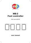
LEDJ StomPar Foot Controller
Safety
WARNING
FOR YOUR OWN SAFETY, PLEASE READ THIS USER MANUAL CAREFULLY
BEFORE YOUR INITIAL START-UP!
CAUTION!
Keep this equipment away from rain,
moisture and liquids.
SAFETY INSTRUCTIONS
Every person involved with the installation, operation & maintenance of this
equipment should:
-
Be competent
-
Follow the instructions of this manual
Before your initial start-up, please make sure that there is no damage caused during
transportation. Should there be any, consult your dealer and do not use the
equipment.
To maintain the equipment in good working condition and to ensure safe operation, it is necessary
for the user to follow the safety instructions and warning notes written in this manual.
Please note that damages caused by user modifications to this equipment are not
subject to warranty.
LEDJ StomPar Foot Controller
Safety
IMPORTANT:
The manufacturer will not accept liability for any resulting damages caused
by the non-observance of this manual or any unauthorised modification to the
equipment.
• Never remove warning or informative labels from the equipment.
• Do not open the equipment and do not modify the equipment.
• Do not connect this equipment to a dimmer-pack.
• Only use the equipment indoors.
• Do not expose to flammable sources, liquids or gases.
• If the equipment has been exposed to drastic temperature fluctuation (e.g. after
transportation), do not switch it on immediately. The arising condensation might damage
the equipment. Leave the equipment switched off until it has reached room temperature.
• If your product fails to function correctly, discontinue use immediately. Pack the unit
securely (preferably in the original packing material), and return it to your Prolight dealer
for service.
• Only use fuses of same type and rating.
• Repairs, servicing and power connection must only be carried out by a qualified
technician. THIS UNIT CONTAINS NO USER SERVICEABLE PARTS.
• WARRANTY; One year from date of purchase.
OPERATING DETERMINATIONS
If this equipment is operated in any other way, than those described in this manual,
the product may suffer damage and the warranty becomes void.
Incorrect operation may lead to danger e.g.: short-circuit, burns, electric shocks,
lamp failure etc.
Do not endanger your own safety and the safety of others!
Incorrect installation or use can cause serious damage to people and property.
Features:
Sound active, auto run, static colour selection and blackout modes
15 preset colours
4 robust foot switches: mode, up/down and blackout
Adjustable sound sensitivity and speed control
LED illumination for each foot switch
6 digit LED display
Built-in programmes
Robust housing
3-Pin XLR out socket
On/Off power switch
Specifications:
Power supply: DC 9-12V 500mA Min. (by adaptor included)
Dimensions: 449 x 162 x 62mm
Weight: 3Kgs
LEDJ StomPar Foot Controller
Operations
Overview (top)
LED Display
Blackout foot switch
Mode foot switch
Down foot switch
Up foot switch
Overview (back)
On/off switch
Sound sensitivity
control
Operations
Speed
control
DMX out socket
Power input
The StomPar foot controller is made specially for use with RGBA products. All of the built-in programmes
can be accessed via the 4 foot switches, the 6 digit LED display allows the user to see what mode or
colour the unit is operating in. Two controls on the rear of the unit allow you to set the sound sensitivity
and chase speed to your desired setting.
Static colour selection mode:
To activate this mode, press the “MODE” foot switch so “rEd” is shown on the LED display, now use the
“UP” and “DOWN” foot switches to select one of the 15 built-in colours. To blackout the unit, press the
“BLACKOUT” foot switch and press it again to return it to the previous setting.
Note: Whilst the unit is in blackout mode, you can select a new colour by using the “UP” and
“DOWN” switches, then when you press blackout again your new color will illuminate.
Sound active mode:
To activate this mode, press the “MODE” foot switch so “SoUNd” is shown on the LED display, now use
the “Sound sensitivity control” to set the desired level. If you require to blackout the unit at any point,
press the “BLACKOUT” foot switch and press it again to return it to the previous setting.
Built-in programmes:
To activate this mode, press the “MODE” foot switch so “Pro--1” is shown on the LED display, now use
the “UP” and “DOWN” foot switches to select between the built-in programmes; “Pro--1” or “Pro--2”.
Now use the “Speed control” to set the desired speed level. To blackout the unit, press the
“BLACKOUT” foot switch and press it again to return it to the previous setting.
“Pro--1” = Colour change (15 colours), “Pro--2” = Colour fade (15 colours)
LEDJ StomPar Foot Controller
Colour Chart
15 Built-in colour chart
Due to the limitations of seven segment displays, the 6 digit LED display can sometimes be hard to
read the colours. So please see the chart below for a quick and easy overview.
6 Digit LED Display
Colour
Red
Green
Blue
Amber
Light Yellow
Light Blue
Violet
Orange
Light Green
Magenta
Cool White
Yellow
Pink
Cyan
Warm White
LEDJ StomPar Foot Controller
DMX Set Up
Notice:
• Be sure to follow figures 2 & 3 when making your own cables. Do not connect the cable’s shield
conductor to the ground lug or allow the shield conductor to come in contact with the XLR’s outer
casing. Grounding the shield could cause a short circuit and erratic behaviour.
Special Note: Line termination:
• When longer runs of cable are used, you may need to use a terminator on the last unit to
avoid erratic behaviour.
Termination reduces signal transmission problems
and interferance. it is always advisable to connect a
DMX terminal, (resistance 120 Ohm 1/4 W) between
pin 2 (DMX-) and pin 3 (DMX+) of the last fixture.
Using a cable terminator (part number CABL90) will decrease the possibilities of erratic
behaviour.
5-Pin XLR DMX Connectors:
• Some manufactures use 5-pin XLR connectors for data transmission in place of 3-pin. 5-Pin
XLR fixtures may be implemented in a 3-pin XLR DMX line. When inserting standard 5-pin
XLR connectors in to a 3-pin line a cable adaptor must be used. The chart below details the
correct cable conversion.
Create the mood
www.prolight.co.uk


