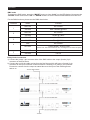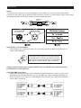
1
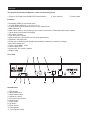
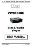
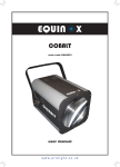
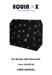
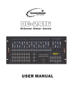
www.prolight.co.uk
User Manual
Equinox 2m Flight Cased
DMX LED Flame Machine
Order code: FLAM12
Safety
Safety
IMPORTANT:
The manufacturer will not accept liability for any resulting damages caused
by the non-observance of this manual or any unauthorised modification to the
equipment.
• Never let the power-cable come into contact with other cables. Handle the power-cable
and all mains voltage connections with particular caution!
• Never remove warning or informative labels from the equipment.
• Do not open the equipment and do not modify the equipment.
• Do not connect this equipment to a dimmer-pack.
• Do not switch the equipment on and off in short intervals, as this will reduce the
system’s life.
• Only use the equipment indoors.
• Do not expose to flammable sources, liquids or gases.
• Always disconnect the power from the mains when equipment is not in use or before
cleaning! Only handle the power-cable by the plug. Never pull out the plug by pulling the
power-cable.
• Make sure that the available voltage is between 220V/240V.
• Make sure that the power-cable is never crimped or damaged. Check the equipment and
the power-cable periodically.
• If the equipment is dropped or damaged, disconnect the mains power supply immediately.
Have a qualified engineer inspect the equipment before operating again.
• If the equipment has been exposed to drastic temperature fluctuation (e.g. after
transportation), do not switch it on immediately. The arising condensation might damage
the equipment. Leave the equipment switched off until it has reached room temperature.
• If your product fails to function correctly, discontinue use immediately. Pack the unit
securely (preferably in the original packing material), and return it to your Prolight dealer
for service.
• Only use fuses of same type and rating.
• Repairs, servicing and power connection must only be carried out by a qualified
technician. THIS UNIT CONTAINS NO USER SERVICEABLE PARTS.
• WARRANTY; One year from date of purchase.
OPERATING DETERMINATIONS
If this equipment is operated in any other way, than those described in this manual,
the product may suffer damage and the warranty becomes void.
Incorrect operation may lead to danger e.g.: short-circuit, burns, electric shocks, LED failure etc.
Do not endanger your own safety and the safety of others!
Incorrect installation or use can cause serious damage to people and property.
Overview
You should find inside the Equinox carton the following items:
1, Equinox 2m Flight Cased DMX LED Flame Machine 2, User manual
3, Power cable
Features:
• Red/amber LEDS for true flame effect
• 18 x 3W RGBA LEDs (R: 3, G: 6, B: 6, A: 3)
• 0-100% dimming and variable strobe (only in stand alone)
• DMX channels: 5
• Static colour mixing, colour change, colour fade, sound active, DMX and master/slave modes
• 4 push button menu with LED display
• IEC power in socket
• 3-pin XLR in/out sockets
• High velocity fan (not suitable for low noise applications)
• Supplied in full flight case
• Heavy duty, industrial grade handles and butterfly catches are riveted for strength.
• Max. flame height: 2m
• Power consumption: 157W
• Power supply 240V
• Dimensions: 561 x 460 x 438mm
• Weight: 20kg
Over View
Identification
1. LED display
2. DMX input socket
3. DMX output socket
4. Sensitivity control
5. IEC power input socket
6. Mode button
7. Enter button
8. Up button
9. Down button
10. Microphone
11. On/off power switch
Operation
Operation:
To activate the unit, first connect the IEC cable into the unit and then connect the plug into a AC 240V
power supply. Once the unit has been connected use the “POWER SWITCH” located next to the
“POWER IEC” input socket to turn the unit ON or OFF.
Operating Instructions
The 2M Flight Cased DMX LED Flame Machine is a DMX-512 controllable, full RGBA colour mixing
Flame Machine made up of high efficiency LED’s. There are four colour groups (red, blue, green and
amber) whose intensity can be controlled individually allowing the creation of a range of colours.
The 2M Flight Cased DMX LED Flame Machine will operate in stand-alone, master/slave, sound
activated and DMX-512 control.
Operation modes
Static colour mode
To access the static colour mode, press the “MODE” button to show “C000” on the LED display. Now
press the “ENTER” button to choose “Cr” (red + amber), “C9” (green) or “Cb” (blue). To adjust the
brightness use the “UP” or “DOWN” buttons to increase or decrease the setting from 00-99.
Examples: If you set Cr, C9 and Cb to zero, the LED flame machine will have no LEDs on (blackout).
If you set Cr to 99 and C9 and Cb to zero, the LED flame machine will be 100% Red and Amber.
To add strobe, press the “ENTER” button and use the “UP” or “DOWN” buttons to increase or
decrease the strobe speed from 00-99.
Note: 00 = Off, 99 = Full on
Colour change mode
To access the colour change mode, press the “MODE” button to show “J000” on the LED display. Now
press the “ENTER” button and use the “UP” or “DOWN” buttons to increase or decrease the speed
from 00-99.
Note: 00 = Slow, 99 = Fast
Colour fade mode
To access the colour fade mode, press the “MODE” button to show “F000” on the LED display. Now
press the “ENTER” button and use the “UP” or “DOWN” buttons to increase or decrease the speed
from 00-99.
Note: 00 = Slow, 99 = Fast
Sound active mode
To access the sound active mode, press the “MODE” button to show “Sund” on the LED display. Now
use the “SENSITIVITY” control on the rear panel to adjust the sound sensitivity level.
Master/slave mode
To set the unit as the master, simply use any one of the above modes.
To set the unit as a slave, press the “MODE” button to show “Slau” on the LED display. Now the slave
unit will follow in sequence with the master unit.
Operation
DMX mode
To access the DMX mode, press the “MODE” button to show “Addr” on the LED display. Now press the
“ENTER” button and use the “UP” or “DOWN” buttons to set the desired DXM address from 000-512.
For the DMX functions, please see the DMX chart below.
Channel
1
2
3
4
5
Value
Function
000-125
No function
126-255
Red + Amber @100%
000-125
No function
126-255
Green @ 100%
000-125
No function
126-255
Blue @ 100%
000
001-255
No function
Colour chase - Slow to Fast
(Please note: This auto activates the fan, overriding the Fan on/Fan off option)
000-125
Fan off
126-255
Fan on
Daisy Chain Connection
1) Connect the (male) 3 pin connector side of the DMX cable to the output (female) 3 pin
connector of the first fixture
2) Connect the end of the cable coming from the first fixture which will have a (female) 3 pin
connector to the input connector of the next fixture consisting of a (male) 3 pin connector.
Proceed to connect from the output as stated above to the input of the following fixture
and so on. DMX Set Up
DMX Control Mode
Operating in a DMX control mode environment gives the user the greatest flexibility when it comes to
customising or creating a show. In this mode you will be able to control each individual trait of the fixture
and each fixture independently. The 2M Flight Cased DMX LED Flame Machine uses 4 channels of
control.
Setting the DMX address
The DMX mode enables the use of a universal DMX controller. Each fixture requires a “start address”
from 1- 511. A fixture requiring one or more channels for control begins to read the data on the channel
indicated by the start address. For example, a fixture that occupies or uses 7 channels of DMX and was
addressed to start on DMX channel 100, would read data from channels: 100,101,102,103,104,105 and
106. Choose a start address so that the channels used do not overlap. E.g. the next unit in the chain
starts at 107.
DMX-512:
• DMX (Digital Multiplex) is a universal protocol used as a form of communication between intelligent
fixtures and controllers. A DMX controller sends DMX data instructions form the controller to the fixture.
DMX data is sent as serial data that travels from fixture to fixture via the DATA “IN” and DATA “OUT” XLR
terminals located on all DMX fixtures (most controllers only have a data “out” terminal).
DMX Linking:
• DMX is a language allowing all makes and models of different manufactures to be linked together and
operate from a single controller, as long as all fixtures and the controller are DMX compliant. To ensure
proper DMX data transmission, when using several DMX fixtures try to use the shortest cable path
possible. The order in which fixtures are connected in a DMX line does not influence the DMX
addressing. For example; a fixture assigned to a DMX address of 1 may be placed anywhere in a DMX
line, at the beginning, at the end, or anywhere in the middle. When a fixture is assigned a DMX address
of 1, the DMX controller knows to send DATA assigned to address 1 to that unit, no matter where it is
located in the DMX chain.
DATA Cable (DMX cable) requirements (for DMX operation):
• The 2M Flight Cased DMX LED Flame Machine can be controlled via DMX-512 protocol. The DMX
address is set on the back of the unit. Your unit and your DMX controller require a standard 3-pin XLR
connector for data input/output (figure 1).
Figure 1
Also remember that DMX cable must be daisy chained and cannot be split.
DMX Set Up
Notice:
• Be sure to follow figures 2 & 3 when making your own cables. Do not connect the cable’s shield
conductor to the ground lug or allow the shield conductor to come in contact with the XLR’s outer casing.
Grounding the shield could cause a short circuit and erratic behaviour.
Special Note: Line termination:
• When longer runs of cable are used, you may need to use a terminator on the last unit to
avoid erratic behaviour.
Termination reduces signal transmission problems
and interferance. it is always advisable to connect a
DMX terminal, (resistance 120 Ohm 1/4 W) between
pin 2 (DMX-) and pin 3 (DMX+) of the last fixture.
Using a cable terminator (part number CABL90 3-pin or CABL89 5-pin) will decrease the
possibilities of erratic behaviour.
5-Pin XLR DMX Connectors:
• Some manufactures use 5-pin XLR connectors for data transmission in place of 3-pin. 5-Pin
XLR fixtures may be implemented in a 3-pin XLR DMX line. When inserting standard 5-pin
XLR connectors in to a 3-pin line a cable adaptor must be used. The chart below details the
correct cable conversion.