1
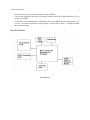
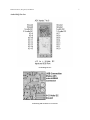
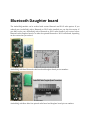
The Ultimate AndroiDAQ Guide
The Ultimate AndroiDAQ Guide goes beyond any user’s
manual with its in depth plethora of examples for data
acquisition circuitry and software code for Android,
LabVIEW, and more.
Rick Fluck
This book is for sale at http://leanpub.com/theultimateandroidaqguide
This version was published on 2014-12-03
This is a Leanpub book. Leanpub empowers authors and publishers with the Lean Publishing
process. Lean Publishing is the act of publishing an in-progress ebook using lightweight tools and
many iterations to get reader feedback, pivot until you have the right book and build traction once
you do.
©2014 Rick Fluck
Tweet This Book!
Please help Rick Fluck by spreading the word about this book on Twitter!
The suggested hashtag for this book is #ultimateandroidaq.
Find out what other people are saying about the book by clicking on this link to search for this
hashtag on Twitter:
https://twitter.com/search?q=#ultimateandroidaq
Contents
Introduction . . . . . . . . . . . . . . . . . . . . . . . . . . . . . . . . . . . . . . . . . . . .
1
AndroiDAQ Data Sheet . . . . . . . . . . . . . . . . . . . . . . . . . . . . . . . . . . . . . .
3
Firmware Source, Prop Tool, and Pinout . . . . . . . . . . . . . . . . . . . . . . . . . . . .
6
Testing the AndroiDAQ Bare Board option . . . . . . . . . . . . . . . . . . . . . . . . . . .
9
Bluetooth Daughter board . . . . . . . . . . . . . . . . . . . . . . . . . . . . . . . . . . . .
12
Connecting AndroiDAQ to Bluetooth . . . . . . . . . . . . . . . . . . . . . . . . . . . . . .
15
Connecting AndroiDAQ to Wi-Fi . . . . . . . . . . . . . . . . . . . . . . . . . . . . . . . .
16
Your Notes . . . . . . . . . . . . . . . . . . . . . . . . . . . . . . . . . . . . . . . . . . . . .
18
Introduction
In the writing this guide, it is my intention to teach young and old students, along with hobbyists in
electronics, the various circuits and methods commonly used in micro-controlled data acquisition
and control systems. I will provide to you not only schematics, but also some theory of operation,
formulas, and design thoughts behind the circuitry, so that you can expound further this information
for your applications.
This guide also presents to you how to use a numerical menu command structure to your advantage,
like the one used in the AndroiDAQ firmware code, and how using this simple menu structure for
multi-core micro-controllers allows you to control parallel processing in ways other popular modules
can not, due to their linear single core processing methods. These simple menu commands simplify
USB, Bluetooth, and Wi-Fi communications with a micro-controller due to their brevity, saving both
bandwidth and time for more important communications like data gathering.
The Ultimate AndroiDAQ Guide not only describes how to setup, modify, and use your AndroiDAQ
module with the AndroiDAQ DEMO application for Android, but it also teaches you how to do these
things with the many other programming languages like LabVIEW, Java, and Python.
The AndroiDAQ module is very small, fully programmable, and very powerful multi-core singleboard micro-controller platform that is used for electronics prototyping and data acquisition.
Its eight processors can operate simultaneously, either independently or cooperatively, sharing
common resources through a central hub. The developer has full control over how and when each
processor is employed; there is no compiler-driven or operating system-driven splitting of tasks
among the multiple processors. A shared system clock keeps each processor on the same time
reference, allowing for true deterministic timing and synchronization.
AndroiDAQ is very design flexible with a plethora of uses for interfacing software languages to
the outside world. AndroiDAQ can be used for robotics, process monitoring and control systems,
smart peripherals, and anything else your imagination can dream up. This module is compatible
with Android, LabVIEW, JAVA, Python, and most other programming languages. This module was
designed to help innovative makers portable device driven and operated products a reality.
Each I/O pin, or channel, can be configured to be a digital input, which reads if the input signal line
is high or low. The logic threshold for digital input operation is ½ VDD or 1.65-volts DC at 3.3-volts
VDD. The I/O pins can also be configured as pulse counters to measure the input signal’s frequency.
Further, the I/O pins can be configured as digital outputs, where a digital low output is zero volts
and a digital high output is VDD or 3.3-volts DC. Lastly, any of the 16 I/O pins can be configured
as a pulsed output channel that can have a set desired frequency and duty cycle for pulse width
modulated signals. Here, a desired frequency and desired duty cycle that you want on each channel
to have is sent to the desired I/O channels. This input frequency and duty cycle is then synthesized
Introduction
2
as an output on the desired pin, or channel. For normal period frequency output, the duty cycle
default is set to 50%.
AndroiDAQ and the AndroiDAQ for Android or LabVIEW DEMO applications were developed to
make it easy for you to interact with the outside world using your Android phone or tablet. This is
done with simple electronic circuits that are connected to the AndroiDAQ module which can: turn
things on or off, measure levels of things, drive electric motors or other electromechanical devices,
make sounds, and much more.
To get started, first you need to install the AndroiDAQ for Android DEMO application onto your
Android device. A downloadable version of AndroiDAQ for Android DEMO is available on Google
Play at:
Android DEMO application on Google Play¹.
Note: You must have a micro-SD card inserted into the micro-SD card slot on
the AndroiDAQ module before you begin to use the AndroiDAQ module with
the AndroiDAQ for Android or LabVIEW DEMO application. The micro-SD card
must be formatted in FAT32 for it to be usable with the AndroiDAQ module.
The recommended size of the micro-SD card is 256MB or larger. The AndroiDAQ
firmware uses subroutines to write data to the SD card and if the SD card is not
present, the firmware will appear to lock up. If you do not desire to have readings
recorded to the SD card, you can comment out the SD card write routines in the
firmware. After this, you do not need an SD card installed on the AndroiDAQ
module.
As a safety precaution, all Android devices come with the option to install “non-market” apps,
disabled by default. To use the source code version of AndroiDAQ for Android DEMO, or to develop
your own version of this application, you’ll have to follow the steps below to get your device settings
configured properly.
•
•
•
•
•
Step 1: Click the MENU button on your Android device.
Step 2: Click on the SETTINGS menu item.
Step 3: Scroll down and click on the APPLICATIONS listing in the list.
Step 4: Ensure that the option “UNKNOWN SOURCES” is checked.
Step 5: Read the warning message presented and then acknowledge it by pressing the OK
button to save this setting.
¹https://play.google.com/store/apps/details?id=com.androidaq&hl=en
AndroiDAQ Data Sheet
Contact Information:
Controlled Capture Systems
208-557-0300
[email protected]
AndroiDAQ Data Acquisition and Control Module
AndroiDAQ Module with xBee WiFI Radio
The 24-channel AndroiDAQ module is very small, fully programmable, multi-cored single-board
data acquisition platform that is used for electronics prototyping and product development. The
module can communicate with the outside world wired and wirelessly using many of the popular
wireless radio technologies.
AndroiDAQ has 16 digital/analog I/O channels, all of which can be used for Counter/Event counting
or for frequency synthesis. It also contains a separate 8-channel 12-bit analog to digital converter, all
of which allows for a sundry of data acquisition applications such as robotics, bio-medical devices,
green technology control, and more. AndroiDAQ has the highest channel count and is the lowest
cost-per-channel device available compared to other name brand low-cost data acquisition modules.
AndroiDAQ Data Sheet
4
FEATURES
•
•
•
•
•
•
•
•
16 channels of I/O. Each channel is user programmable as either an input or an output channel.
8-channel 12-bit Analog to Digital Converter (3.3-volt input max.)
Based on Parallax’s Propeller multi-core microcontroller.
Built-in micro SD card holder.
USB connectivity, with optional Bluetooth, Wi-Fi, ZigBee, or xBee radios.
Built-in Real Time Clock with battery back-up.
9 to 12-volt DC input power or can be powered via AC power supply (sold separately).
Breadboard prototyping spacing (board dimensions: 3.00” X 1.300”, pin spacing: 1.100” X
0.100”).
• User customizable internal firmware and open source sample software also customizable by
you (or by Controlled Capture Systems) for your projects and applications.
• Free downloads of our AndroiDAQ DEMO for Android, AndroiDAQ for DEMO LabVIEW
applications and MCU firmware code.
• Designed and manufactured in the USA.
APPLICATIONS
•
•
•
•
•
•
•
•
•
•
•
Scientific experiments, class projects, and field measurements.
Stepper, servo, brush-less and other DC motor and motion controls.
Android and other smart peripherals including smart vending machines.
2D and 3D printer control and/or multi-axis CNC machine control.
Solar and electric vehicle on-board power management systems.
– Biometric and medical smart devices and equipment.
Single to multi-wheeled driven robotic vehicles.
Multicopter, Quadcopter, and other unmanned aerial vehicles or drones.
Quadrapod, Hexapod and other multi-legged robots.
Bipods, balancing robots, and more fun with robotics.
Weather, earthquake, data recording, and other remote testing and sensing operations.
Home security, automated watering systems, Christmas lighting control and much more,
limited only by your imagination…
SPECIFICATIONS
• 8 (eight) 32-bit processors that run independently at 80MHz, for up to 160MIPS, which can
also synthesize NTSC video and speech without extra support chips.
• Digital inputs (I/O speed up to 160 MHz, 5-volt DC tolerant)
• Digital outputs (sink/source 40mA max. @ 3.3-volt)
5
AndroiDAQ Data Sheet
• Event counters or frequency measurements (up to 40MHz)
• User settable frequency and duty cycle output synthesis for Pulse Width Modulation (1 Hz to
as high as 320KHz)
• 12-bit, ADC can be sampled up to 113K Samples/Sec total (50KSPS typical). +Input power 9-12volt DC ∼40-75mA current draw. Output power 3.3-volts and 5-volts at ∼.75-amps available
for external circuitry.
BLOCK DIAGRAM
Block Diagram
Firmware Source, Prop Tool, and
Pinout
The firmware for the AndroiDAQ module can be found at:
Android Firmware²
On that site your will find the zipped firmware files that contain the source code and the Parallax
Propeller Tool, which is an integrated development environment or IDE for the Parallax Propeller
microcontroller chip that AndroiDAQ uses. We recommend that you study and understand the
operation of this source code before you make any modifications to it. You can read more about
the Parallax Propeller microcontroller chip that is used on the AndroiDAQ module and the SPIN
language that makes up the AndroiDAQ firmware code at:
Parallax Propeller Website³
And
Propeller Manual⁴
After you download the new firmware simply unzip the folder to your desktop. In the resultant
folder you will find the USB driver that is necessary for you computer to communicate with the
AndroiDAQ module. This file is called: CDM_2.04.16.exe. The driver was written by the company
FTDI who is the supplier of the USB UART chip that AndroiDAQ uses. Simple click on the CDM_2.04.16.exe file to install the driver. After the USB driver is installed open the Propeller Tool by
clicking on the Propeller.exe file. In the Propeller Tool, find the AndroiDAQRev(version number).spin
file in that resultant unzipped folder using File, Open…, and click on the AndroiDAQRev(version
number).spin file to open it in the Propeller tool. Press F8 in the Propeller Tool to ensure that the
firmware compiles, if not please contact us. Connect the AndroiDAQ module to a USB port on
your computer, press F7 in the Propeller Tool to ensure that the Propeller Tool finds the Propeller
microcontroller chip on the AndroiDAQ module, and lastly press F11 to reprogram the AndroiDAQ
module’s firmware.
²https://code.google.com/p/androidaq-demo-enhancement-project/
³http://www.parallax.com/propeller/
⁴http://www.parallax.com/Portals/0/Downloads/docs/prod/prop/Web-PropellerManual-v1.2.pdf
7
Firmware Source, Prop Tool, and Pinout
AndroiDAQ Pin Out
AndroiDAQ Pin Out
AndroiDAQ USB and Power Connections
Firmware Source, Prop Tool, and Pinout
8
Note: The 3.3-volts can supply ∼400mA and the 5-volts can supply ∼ .75 amps. The
ADC is input only, 3.3-volts DC max. The AndroiDAQ I/O pins: Can source/sink 40mA
each at 3.3 VDC. I/O pins are compatible with 5-volt DC input, as they each have 1K
series resistor on each input.
For the AndroiDAQ power connector mate, we suggest a Molex connector, part number 50-57-9002
which is available at Mouser or Digikey. When you order this connector, you will also need to order
the terminals for that connector, which you can solder to the power supply wires, vice crimping
the terminals to the wire. You can also order this connector, Molex part number 14-56-2029 which
includes the terminals. If you desire to crimp your terminals, vice soldering them, a 601-24-7373P
crimper, available at Mouser may be used.
To power your AndroiDAQ module, a 9-volt battery with the above connector or AC wall pluggable
12-volt DC out power supply can be used, such as a Cincon TRG1512 which is available at Mouser
under part number: 418-TRG1512-V. This power supply will also need to be modified with the correct
AndroiDAQ connector.
Testing the AndroiDAQ Bare Board
option
If you ordered the AndroiDAQ Bare Board option you will receive by email the build sheet with part
numbers and notes on assembling the module and radio daughter board. After all parts are installed
on your AndroiDAQ module and radio daughter board, please follow the below sequence to ensure
that your firmware is properly loaded onto your AndroiDAQ module.
1. We use LabVIEW and our AndroiDAQ LabVIEW library for these test steps. If you do not have
LabVIEW you can download our stand-alone AndroiDAQ DEMO for LabVIEW application at
https://code.google.com/p/androidaq-demo-enhancement-project/. After you download the
zipped file, unzip it and click on the setup.exe file inside the resulting folder. This will install
the AndroiDAQ DEMO for LabVIEW application and the LabVIEW Runtime engine required
to run this application.
2. If you haven’t already, install Parallax’s Propeller/Spin Tool⁵ Software onto your laptop or
desktop Windows computer. It is also included in the AndroiDAQ firmware download file.
After you download the zipped file from the link above, unzip it and click on the setup.exe
file inside the resulting folder to install the Propeller/Spin Tool Software.
3. If you haven’t already, install a micro-SD card into the AndroiDAQ’s SD card slot. The
recommended size for the SD memory card is 256MB or larger and it must be formatted in
FAT32 to operate properly with the onboard AndroiDAQ file system.
4. Apply power to the AndroiDAQ module on JP6. As stated earlier in this manual, the pin
nearest the JP6 silkscreen designator is the positive pin, or pin 1, and pin 2 is ground.
We recommend using a 9-volt battery or 12-volt DC wall wart style power source. After
connecting the power, check that the 5v and 3.3v pins measure 5-volts DC and 3.3-volts
DC respectively in reference to the Gnd pins. If not, unplug the AndroiDAQ module and
inspect your component orientations to ensure that none of the IC chips are installed in the
wrong direction. This is a common mistake which will require you to remove the chip and
reinstall a new one in the correct orientation. The component may not be damaged, please
check the manufacturer’s component data sheet to see if it is reverse voltage protected. When
the voltages measure correctly, leave the AndroiDAQ module plugged into your power source.
5. Connect your laptop or desktop computer to the AndroiDAQ module via a USB cable. Your
USB cable should have a microUSB-b connector on one end to attach to the AndroiDAQ
module. Most Android phones use this style of connector for their USB port so you may have
one lying around, or you can order one from Mouser under their part number: 552-IPUSB1MSR.
⁵http://www.parallax.com/downloads/propeller-tool-software
Testing the AndroiDAQ Bare Board option
10
6. If your Windows system does not find a driver for the AndroiDAQ module after it is plugged
in, unplug it from the USB port and then install the CDM 2.04.16.exe file that is located in
the data folder that is located in the directory where you installed the AndroiDAQ DEMO for
LabVIEW application. The CDM 2.04.16.exe installs the FTD drivers for the USB portion of
the AndroiDAQ module. If your Windows system still doesn’t recognize your AndroiDAQ
module, remove the USB cable and power source and check the connections on the USB
connector JP2, the connections on the FT232R chip (U4), and the connections for the RX/TX
switch (U3), and all other connections on your AndroiDAQ module.
7. After your AndroiDAQ module is recognized by the Windows system by plugging in the
USB cable with the AndroiDAQ module powered on, start the Propeller/Spin Tool Software
program and then ensure that the Propeller/Spin Tool Software recognizes your AndroiDAQ’s
Propeller chip by pressing the F7 key in the Propeller/Spin Tool Software. The software will
tell you if it found AndroiDAQ’s Propeller chip and on which COM port it is on. If it is not
found, check your connections on U2 and U6 and try again until the Propeller chip is found
by the Propeller/Spin Tool Software.
8. If you haven’t already, download Latest AndroiDAQ firmware⁶ and save it to your computer.
Unzip this zipped folder and then in the Propeller/Spin Tool Software load the firmware spin
code by clicking on File then Open…, and then select the AndroiDAQRev(revx.xxx).spin file
in the folder that you just unzipped. When done properly, the Propeller/Spin Tool Software
will load and then display the AndroiDAQ main spin code in the right-hand side of the user’s
interface.
9. You program your AndroiDAQ module by pressing F11 in the Propeller/Spin Tool Software,
after the AndroiDAQRev(revx.xxx).spin code is loaded into the Propeller/Spin Tool Software.
You will be alerted if the programming of the AndroiDAQ module was successful or if it failed.
10. Find the AndroiDAQ DEMO for LabVIEW icon under Windows’ Start, All Programs,
AndroiDAQ and then click on the AndroiDAQ.exe icon. With the AndroiDAQ module
connected to your computer via USB as described above, the AndroiDAQ DEMO for LabVIEW
application will automatically find your AndroiDAQ module.
11. After the above tests have passed and your AndroiDAQ firmware is installed successfully, you
can now try to read AndroiDAQ’s Real Time Clock. This is done by pressing the “Read RTC
Clock” button on the LabVIEW DEMO screen. If successful you should see a date and time
similar to: 01/01/200 00:00:80.
12. To set the AndroiDAQ Real Time Clock to real time, press the “Set RTC Clock” button in
LabVIEW DEMO screen. This will sent to the AndroiDAQ module your laptop or desktop’s
current date and time setting.
13. Apply one of the 3.3-volts DC outputs, found on either side of the AndroiDAQ I/O pins toward
the green terminal block ADC connector, to I/O port 0 of the ADC input and ensure that that
channel can read the 3.3-volt signal by pressing the “Read Voltages from AndroiDAQ” button.
Repeat this step for each ADC input pin and ensure that the voltage is read.
⁶https://code.google.com/p/androidaq-demo-enhancement-project/
Testing the AndroiDAQ Bare Board option
11
14. Set up an LED test circuit by connecting any of the four “Gnd” pins on the AndroiDAQ module
to one end of a 470 ohm resistor. The other end of the resistor is connected to an LED (cathode)
and then the LED (anode) is connected to a length of wire.
15. Attach the loose end of the wire from step 14 above to I/O Port 0 of the AndroiDAQ I/O pins,
not the green ADC terminal. This will connect the LED anode to the pin in test. Set I/O channel
0 to an output by clicking on the “Input or Output” button for that channel. This will turn the
button on or change it to bright green. Ensure that the Output Type for this channel is set to
“digital” and then toggle the “Output Setting” to high (see Legend in DEMO application) and
then click on the “Set Outputs of AndroiDAQ” button to ensure that the LED lights up. Toggle
the “Output Setting” to low to ensure that the LED turns off. Do this for every I/O pin.
16. If any of the above tests fail, check your solder connections and part orientations on your
AndroiDAQ module using a magnifying glass. Please contact us if you need assistance.
Bluetooth Daughter board
The AndroiDAQ module can be ordered with various Bluetooth and Wi-Fi radio options. If you
ordered your AndroiDAQ with a Bluetooth or Wi-Fi radio installed you can skip this section. If
you didn’t order your AndroiDAQ with a Bluetooth or Wi-Fi radio installed, you received a bare
Bluetooth radio daughter board or an xBee foot-printed Bluetooth or Wi-Fi radio board, depending
on the version that you ordered.
AndroiDAQ with bare Bluetooth radio board and daughter board pin out numbers.
AndroiDAQ with Bare xBee foot-printed radio board and daughter board pin out numbers.
Bluetooth Daughter board
13
You can order and then install a Bluetooth radio or Wi-Fi radio of your choice along with the
connecting 5-pin header on the bottom of the daughter board. The connecting 5-pin header can be
ordered from Digikey or Mouser under Harwin part number M52-040000P0545. This part is surface
mounted, but can be easily soldered to the daughter board by hand using a little patience and preplanning.
The following Bluetooth radios are pin to pin compatible with the AndroiDAQ Bluetooth Daughter
board:
Class 1 Radios: Approximately 100 meter transmit/receive distance.
Roving Networks RN-41:
This radio is a Class 1 Bluetooth module which is perfect for battery powered applications and
by default is ready to use in the SPP (Serial Port Profile) configuration. It uses only 250 µA in sleep
mode while still being discoverable and connectable. Multiple low power modes available allow you
to dial in the lowest power profile for your application. With its high performance on-chip antenna
and support for Bluetooth Enhanced Data Rate (EDR), the RN-41 delivers up to 3 Mbps data rate for
distances to 100 meters. The RN-41 is the perfect product for engineers adding Bluetooth capability to
their product without spending significant time and money to develop Bluetooth specific hardware
and software. Digikey part#: 740-1007-ND
Class 2 Radios: Approximately 20 meter transmit/Receive distance.
Roving Networks RN-42:
The RN-42 is form, function, and pin compatible with the RN-41. The primary difference between
the RN-42 and RN-41 is that the RN-42 is a Class 2 device, meaning its range is about 50 to 60 feet and
correspondingly the power consumption is reduced. The RN-42 is perfect for short range, battery
powered applications and by default is ready to use in the SPP (Serial Port Profile) configuration.
The RN-42 uses only 26 µA while in sleep mode. Multiple user-configurable power modes allow the
user to dial in the lowest power profile for a given application. Digikey part#: 740-1038-2-ND
The following Bluetooth and Wi-Fi xBee foot-printed radios are compatible with the AndroiDAQ
xBee radio Daughter board:
Class 1 Radios: Approximately 100 meter transmit/receive distance.
Roving Networks RN41XV:
The RN41XV module provides drop-in, certified Bluetooth connectivity for existing systems using
802.15.4 modules. Based on the popular 2 x 10 (2mm) socket footprint often found in embedded
applications, the RN41XV offers a complete wireless solution for customers looking to migrate to
a standard protocol without modifying existing hardware. The RN41XV is built upon Microchip’s
RN41 low power Bluetooth module. The module has an embedded Bluetooth stack and supports
multiple interface protocols and profiles including the commonly used SPP and HID profiles.
Digikey part#: RN41XVC-I/RM-ND or RN41XVU-I/RM-ND
Wi-Fi radios:
Bluetooth Daughter board
14
Roving Networks RN171XV:
The RN171XV module is a certified Wi-Fi solution especially designed for customers who want to
migrate their existing 802.15.4 architecture to a standard TCP/IP based platform without redesigning
their existing hardware. The RN171XV module is based upon Microchip’s robust RN171 Wi-Fi
module and incorporates an 802.11 b/g radio, 32 bit processor, TCP/IP stack, real-time clock,
crypto accelerator, power management unit and analog sensor interface. The RN171XV module
supports infrastructure networking for worldwide internet access directly by every node and adhoc connectivity for fully connected point to point networks, unlike many 802.15.4 implementations
that need extensive, custom application profiles and additional bridging products. Digikey part#:
740-1044-ND or RN171XVS-I/RM-ND
When installing the AndroiDAQ Bluetooth/Wi-Fi Daughter Module, ensure that the antenna of
your Bluetooth or Wi-Fi radio is pointing toward the AndroiDAQ screw terminal which is used for
voltage measurements from the ADC.
Connecting AndroiDAQ to Bluetooth
When you first start the AndroiDAQ for Android DEMO application, you will be asked what kind
of connection you desire, Bluetooth or Wi-Fi. To connect your AndroiDAQ to Bluetooth, press the
Bluetooth button. If Bluetooth wasn’t enabled on your Android device, the DEMO application will
ask you for your permission to enable Bluetooth radio functions. Press Yes. After your Android
device has turned on your device’s Bluetooth radio, you will then need to press your menu button
to open the DEMO menu. Select the menu item ‘Connect a device’. This opens a dialog box that
contains a list of all paired Bluetooth devices on your Android device; your list may be empty due to
not pairing any devices to your Android device. Here, you need to press the ‘Scan for devices’ button
under this dialog, which helps the Android system to find the AndroiDAQ Bluetooth module. You
will then be prompted to input the Bluetooth module’s passkey which is 1234. This will aid in the
pairing of the Bluetooth module to your Android device.
After the ‘Scan for devices’ has finished, you then select your AndroiDAQ Bluetooth radio on the
list of Bluetooth devices found. The numbers shown on the list, per Bluetooth radio found, are the
last four digits of the AndroiDAQ Bluetooth modules serial number. DEMO will then connect to
your Bluetooth radio module, if it is powered on via the AndroiDAQ module which also needs to
have power applied to it. If your Bluetooth radio is not found, due to the module not being powered
on or something else, you will need to rescan your Bluetooth devices, as stated above, to lock your
Android device with the radio’s availability.
We have found that if you dump the AndroiDAQ for Android DEMO application, by pressing the
back button, without first disconnecting the Bluetooth connection under the Menu beforehand, then
you will need to ‘Scan for devices’ again to lock the radio to the Android device. We have also
observed that there are times where you will also need to disable and re-enable the Bluetooth radio
on your Android device to re-lock on to any Bluetooth radio. We are not sure why the Android OS
operates this way.
Upon subsequent restarts of the DEMO application, when you restart the DEMO application under
Bluetooth, you will need to connect to your radio via the Menu list item ‘Connect a device’, it is not
automatic.
Connecting AndroiDAQ to Wi-Fi
When you order the AndroiDAQ module with the Wi-Fi radio option, we do the preliminary setup
here at the factory to test your radio to ensure proper operation with your AndroiDAQ module,
though you will need to reconfigure the Wi-Fi module to log onto your Wi-Fi network using your
Wi-Fi network’s SSID and its password when you receive your Wi-Fi module.
To do this, please first download the Roving Networks WiFly User’s Manual at:
Roving Networks WiFly User’s Manual⁷
Read it to understand your RN-XV module and to learn how to place the Wi-Fi module into
Command Mode and to configure the module in either Ad-Hoc mode (by providing 3.3-volts DC to
pin 8 before powering up the Wi-Fi module) or via Serial communications using a USB adapter like
this one:
Propeller Plug⁸
Where you can use the Propeller Plug to configure your Wi-Fi module using USB and a serial
terminal program such as the Parallax Serial Terminal (available here:
Parallax Serial Terminal⁹
And using a circuit like the example below:
Example Propeller Plug to Radio Connection
Or you can order a module like this one to connect via USB to configure your Wi-Fi module:
xBee Explorer¹⁰
When the Wi-Fi module is in the Command Mode in either Ad hoc or via USB serial link, please
enter the following commands to configure your Wi-Fi module to your Wi-Fi networks SSID and
password:
⁷http://ww1.microchip.com/downloads/en/DeviceDoc/50002230A.pdf
⁸http://www.parallax.com/product/32201
⁹https://code.google.com/p/androidaq-demo-enhancement-project/downloads/detail?name=PST.exe.zip
¹⁰https://www.sparkfun.com/products/8687
Connecting AndroiDAQ to Wi-Fi
17
set wlan ssid (your Wi-Fi network’s name)
set wlan phrase (your Wi-Fi network’s log-in password)
set opt jointmr 20000
set uart baud 115200
set wlan join 1
set comm remote 0
set comm match 10
set comm open 0
set comm. Close 0
save
reboot
After these steps are complete, your RN-XV radio will reboot and try to connect to your Wi-Fi
network (note: if you placed the module into Ad hoc mode, you must remove the wire from pin
8 so that the module reboots normally and not in Ad hoc mode). After you have verified that is it
properly connecting to your Wi-Fi network (see WiFly User’s Manual) you can now remove the RNXV from your USB adapter (if applicable) and then install your RN-XV radio onto the AndroiDAQ
radio daughter board and connect this assembly to your AndroiDAQ module.
Below are the factory commands that we use to configure RN-XV modules to run with AndroiDAQ.
If you run into any problems with the configuration of your RN-XV radio you may need to re-enter
these commands to ensure compatibility with the AndroiDAQ module. This can be done via serial
link or in Ad hoc mode (see WiFly User’s Manual).
factory RESET
set wlan ssid “your network’s name”
set wlan phrase “your network’s password
set opt jointmr 20000
set uart baud 115200
set comm match 10
set wlan join 1
set comm. Remote 0
save
reboot
When you first start the AndroiDAQ for Android DEMO application, you will be asked what kind
of connection you desire, Bluetooth or Wi-Fi. To connect your AndroiDAQ to Wi-Fi, press the Wi-Fi
button. You will then be asked for the TCP address of the Wi-Fi radio connected to your network
(see WiFly User’s Manual).
Your Notes