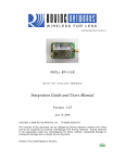
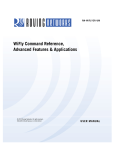
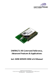
1
Lab Manual for RN-174
174 Evaluation Board
MASTERs 2012
Lab Manual for RN
RN-174 Evaluation Board
Lab 1 Instructions
Lab 2 Instructions
Lab 3 Instructions
Lab 4 Instructions
Lab 5 Instructions
Table of Contents
4
13
233
299
34
Learn How Easy It Is to Add Wi-Fi
Fi to
Your
our Embedded System
Page | 1
Lab Manual for RN-174
174 Evaluation Board
Hardware Architecture: Development Environment
Page | 2
Lab Manual for RN-174 Evaluation Board
Lab Equipment
For this lab, you need the following hardware and software.
Hardware
• RN-174 evaluation board, which contains the RN-171 WiFly module
• Personal computer with a USB port
• USB-to-serial cable
• Null modem
• 10-pin serial cable
• 9-V battery clip
Software
• Tera Term software (http://sourceforge.jp/projects/ttssh2/releases/)
• Portpeeker software ( http://www.linklogger.com/portpeeker.htm)
Page | 3
Lab Manual for RN-174 Evaluation Board
Lab 1:
Association & UDP
Purpose:
This lab will teach you how to:
•
•
•
•
Differentiate between infrastructure and ad hoc networks.
Configure module parameters.
Scan, join, and authenticate to wireless networks.
Discover the WiFly module on your wireless network via UDP.
Page | 4
Overview:
In this procedure, you will set up hardware, configure the module on the evaluation
board, associate with a network, and configure and capture UDP data.
The WiFly module supports the following security modes:
•
•
•
•
WEP 64, WEP 128 OLD/NOT SECURE
WPA1 TKIP
WPA2 AES has not been compromised
Enterprise is not currently supported
Infrastructure Networking
!
Ad Hoc Networking
Page | 5
Lab Manual for RN-174 Evaluation Board
Procedure (Part 1):
1. Connect the evaluation board.
a. Connect the board to your computer.
b. Connect the battery (the green LED blinks slowly).
c. Use the device manager to find the COM port.
2. Launch command mode.
a. Run Tera Term.
b. Open the assigned COM port. The serial port settings are: 9600 baud, 8
bits, no parity, 1 stop bit, and no flow control.
c. Type $$$.
d. The module responds with <CMD>.
3. Review and reset the configuration.
a. Check the configuration and firmware version.
i. get e
ii. ver
b. Perform a factory reset (starts module in a known state).
i. factory R
ii. reboot
Page | 6
Lab Manual for RN-174 Evaluation Board
4. Search for networks.
a. $$$ (enter command mode)
b. scan
5. Join a network.
a. join # 1 (remember the spaces)
b. leave
c. join <string>
(e.g., join RovingNET)
d. leave
6. Auto-join a network with persistent configuration.
a. set wlan ssid <string>
b. set wlan pass <string>
c. save
d. reboot
TIP: If the network is secure, set the pass phrase with set wlan pass <string> before
joining the network.
Page | 7
Lab Manual for RN-174 Evaluation Board
Lab 1 Interim Summary
So far, you have configured the module via the UART in command mode. Next, you will
observe the Wi-Fi activity using PortPeeker on a PC.
Wi-Fi
User Data
A
B
UART
$$$
WiFly
Module
Wi-Fi Interface
Command
Mode
Procedure (Part 2):
1. Associate the PC with the same AP as the module.
a. Enter command mode and retrieve the module’s IP address.
b. Ensure that the PC is on the same subnet.
2. Launch and Configure PortPeeker.
a. Click configure.
b. Set port number to 55555 (default).
c. Set protocol to UDP.
d. Click OK.
3. Start UDP Packet Capture by clicking Start.
If the PC & module are on same subnet, broadcast packets are shown.
If there are multiple nodes on the network, look for YOUR IP address.
Page | 8
Lab Manual for RN-174 Evaluation Board
The following figure illustrates the process of device discovery via UDP broadcast. The
module sends a UDP broadcast at programmable intervals to make itself discoverable.
The UDP broadcast contains information that identifies the module on the network.
I’m
here
Roving
Networks
Device
I’m
here
Roving
Networks
Device
192.168.0.3
192.168.0.6
I’m
here
Roving
Networks
Device
192.168.0.7
174.201.25.16
I’m
here
To Internet
I’m
here
Roving
Networks
Device
Access Point
DHCP server
I’m
here
Roving
Networks
Device
192.168.0.5
I’m
here
192.168.0.2
192.168.0.1
Who is
there
Roving
Networks
Device
192.168.0.8
Roving
Networks
Device
192.168.0.4
UDP Server
192.168.0.100
4. Set the UDP broadcast interval.
a. Enter command mode
i. get broadcast
(observe current interval)
ii. set b i 3
(b=broadcast, i=interval)
iii. save & reboot
b. Review the UDP messages in PortPeeker.
5. Enable the sensor data in the UDP broadcast.
a. Enter command mode.
i. set q s 0xff
(set sensor mask)
ii. save to make persistent (reboot not required).
b. Review the UDP messages in PortPeeker.
Page | 9
Lab Manual for RN-174 Evaluation Board
Device names can identify products on the network. You can also append the device ID
to the UDP broadcast.
6. Set the device ID.
a. Enter command mode.
i. get option
ii. set o d RockAndRollWiFi (o=optional, d=deviceID)
iii. save & reboot
b. Review the UDP messages in PortPeeker.
7. Set the broadcast UDP port.
a. Enter command mode.
i. get broadcast
ii. set b p 50000 (b=broadcast, p=port)
iii. Save & reboot not required.
b. Reconfigure PortPeeker to listen for UDP packets on port 50000
c. Review the UDP messages in PortPeeker.
TIP: UDP Broadcast on by Default. Set Interval to 0 to Turn It Off.
Page | 10
Lab Manual for RN-174 Evaluation Board
8. UDP mode is not enabled by default. Enable UDP by setting the remote host,
port, and protocol.
a. Enter command mode.
i. factory R
ii. Associate with AP
iii. set ip host <address>
iv. set ip remote 50000
v. set ip proto 1 (IP protocol bitmask; 1 = UDP, see following
table)
Bit Position
0
1
2
3
4
b.
Protocol
UDP
TCP Server & Client (Default)
Secure (only receive packets with IP address
matches the store host IP)
TCP Client only
HTTP client mode
vi. set comm timer 1000 (try 10, see the change)
vii. get ip
viii. save & reboot
Type characters; they appear in PortPeeker.
TIP: The IP Protocol Value Is a Bit Mask. You Can Enable Both TCP & UDP Messages.
Page | 11
Lab Manual for RN-174 Evaluation Board
LAB 1 Conclusion
You have completed Lab 1. You have learned that:
•
•
•
•
The RN-174-K with a terminal emulator and serial cable provides a simple,
effective development environment.
Joining networks is easy.
You can discover WiFly devices via UDP broadcast.
The module sends UART data as UDP packets when associated with a
network in UDP mode.
Page | 12
Lab Manual for RN-174 Evaluation Board
Lab 2:
TCP
Purpose:
This lab will teach you how to:
•
•
•
•
•
•
Connect from the module to a remote host using TCP (client).
Connect to module from remote host using TCP (server).
Distinguish between TCP modes.
Automatically open TCP connections using a timer.
Control TCP connections with a microcontroller.
Trigger a TCP flush based on different events.
TCP connections are point-to-point connections that provide reliable, guaranteed, in
order data delivery. They are also known as sockets. See the following figure.
Remote
Host
RN-134-K
192.168.1.50
Listen on Port 2000
Access Point
DHCP server
open 192.168.1.200 5000
WiFly Module Opens TCP Connection
Sensing applications
Sending data to web server
Data acquisition systems
Fleet management
192.168.1.200
Listen on Port 5000
open 192.168.1.50 2000
Remote Host Opens TCP Connection
Industrial controls
Home automation
Universal remotes
Page | 13
Procedure:
1. Associate your computer with the AP.
2. Launch PortPeeke.
3. Configure PortPeeke.
a. Click Configure (note your PC’s IP address in the Interface box).
b. Set port to 5000 (the port number matches the remote port of the WiFly
module).
c. Set the protocol to TCP.
4. Click Start to capture TCP packets.
Page | 14
Lab Manual for RN-174 Evaluation Board
5. With the module connected to the PC over the USB-Serial cable, open Tera
Term on the serial COM port.
6. Restore the module to the factory defaults:
a. Enter command mode.
b. factory R
c. Associate with AP.
d. save & reboot
7. Open a TCP connection using the command open <IP_address> 5000
*OPEN* is shown on serial port (Tera Term window) and a packet with *HELLO*
is shown on PortPeeker.
8. Close the TCP connection:
a. Enter command mode.
b. close
c. Close string *CLOS* displayed in Tera Term.
9. Extra credit: change the COM timer to 2000 and observe the difference on Port
Peeker.
Page | 15
Lab Manual for RN-174 Evaluation Board
*HELLO*
10. In command mode, obtain the module’s IP address using get ip.
11. Open Telnet Connection from PC Using Tera Term (Use Existing Instance)
a. Click File > New connection.
b. Select TCP/IP.
c. Select Telnet.
d. In Host field, type the module’s IP address.
e. TCP port# is 2000 (default listening port).
f. Click OK.
The *HELLO* message is shown in the Telnet window indicating a successful
TCP connection.
12. Type in the Telnet window; data appears in the serial port window and vice
versa.
13. You can configure the module remotely over Telnet by entering command mode.
The module supports three TCP modes:
•
•
•
TCP client and server mode
– Default mode initiates and accepts TCP connections
– Currently supports one active connection at a time
– Concurrent TCP connections supported in future
TCP client ONLY mode
– ONLY initiates TCP connections; cannot accept incoming connections
Secure mode
– ONLY receives packets from host that matches stored host IP address
TIP: Refer to User Manual for More Details on TCP Modes
Page | 16
Lab Manual for RN-174
174 Evaluation Board
14. Set up the module in TCP mode.
a. set ip proto 8
b. save & reboot
15. Open a new Telnet connection to the module from Tera Term. The second
s
connection is refused, indicating that the TCP_Client mode is working correctly.
The module can automatically open a TCP connection to the remote host on powerup or
when waking from sleep.
•
•
•
•
Auto-Connect
Connect Controlled by autoconn Setting
– set sys auto 1
// Attempts to open TCP connection immediately
once only
– set sys auto <value
value>
// Attempts to open TCP connection every
// <value> seconds
– set sys auto 255
// Attempts to open TCP connection once &
// go back to sleep immediately
// when connection is closed
Auto-Connect
Connect Requires Module to Store Remote Host’s IP Address & Port #
– set ip host <host
host IP address
address>
– set ip remote <port
port>
Once TCP Connection Is Opened, It Can Be Closed in Several Ways
– close command
– Idle timer
– Remote host
Idle Timer Closes TCP Connection after Preset # of Seconds of No Activity
(No Tx or Rx) on the TCP Link
– set com idle <value
value>
//Closes the TCP connection after <value> seconds
of inactivity
Page | 17
Lab Manual for RN-174 Evaluation Board
*OPEN**CLOS*…
16. Configure the module open a TCP Connection Every 10 seconds, Drops
Connection after 3 seconds Inactivity
a. set ip host <address>
b. set ip remote 5000
c. set sys auto 10
d. set comm idle 3
e. save
f. reboot
17. PortPeeker: Connection Opens & Closes
18. Tera Term: Open & Close Strings Shown when Each Connection Opens &
Closes
The firmware uses GPIO 4, 5 & 6 to blink the status LEDs on the evaluation board (see
Section 2.4 in the user manual for the standard LED function). Alternative functions are
described below:
GPIO
Function
Description
4 (GRN)
Output
High once associated, authenticated & has IP address.
5 (RED)
Input
Set high to trigger TCP connection, low to disconnect.
6 (YLW)
Output
High when connected over TCP, low when disconnected.
The microcontroller opens or closes the TCP connection to the stored remote host by
driving GPIO5 high or low. This setup requires a hardware configuration that is not part
of this lab. The microcontroller can monitor the TCP connection status by readying
GPIO6:
•
•
High = Connected
Low = Not Connected
Page | 18
Lab Manual for RN-174 Evaluation Board
19. Enable Alternative Functions
a. set wlan ssid <string>
b. set sys iofunc 0x70
c. save
d. reboot
e. Evaluation board LEDs do not turn on
20. After Module Associates with AP
a. Associate with AP
b. save & reboot
c. Green LED goes on (GPIO4)
21. Connect/Disconnect TCP Connection
a. Enter command mode ($$$)
b. open <address><value>
c. Red LED blinks & connection closed because RN-174-K board’s GPIO5
pulled to GND
d. Enter command mode ($$$)
e. leave
// disassociate from AP
f. Green LED goes OFF
Page | 19
Lab Manual for RN-174 Evaluation Board
22. Microcontroller Can Look for UART comm Strings as Indication of TCP
Connection Status:
a. Factory reset
b. reboot
c. Associate with AP
d. set ip host <address>
e. set ip remote 5000
f. set comm open HAPPY
g. set comm close HOLIDAYS
h. set comm remote HAPPY_NEW_YEAR
i. save & reboot
j. Enter command mode
k. open
l. See open string in Tera Term
m. See remote string in PortPeeker
n. Enter command mode
o. close
p. See close string in Tera Term
Tip: Microcontroller Can Read UART Open & Close Strings to Determine TCP
Connection Status
When data is written to the module’s UART, the TCP packets are forwarded based on:
• Flush timer
• Flush size
• Match character
A TCP packet is sent when any of these events occur. The parameters are logically
ORed to determine when a TCP packet is sent. When configured correctly, the module
can be optimized for low latency or high throughput.
• Low latency: use lower flush timer value and flush size
• High throughput: use higher flush timer value and flush size
Tip: Module Tries to Optimize Automatically for Bandwidth by Increasing Default Flush
Size with Higher Baud Rates
Page | 20
Lab Manual for RN-174 Evaluation Board
23. Forwarding Packets Based on Flush Timer
a. set comm timer 1000
b. save
c. open
d. Type text after TCP connection opens
e. After you stop typing, TCP packet is sent
1 second later
24. Forward Packets Based on Match Character
a. set c t 0
(why do we send this command?)
b. set comm match 65
This parameter expects ASCII decimal character or HEX value of the
match character (e.g., 65 = Capital A)
c. save
d. open
e. Type 12345678A
f. TCP packet sent out after you type A character
g. Observe packet in PortPeeker
25. What Do You Learn from Using ‘get c’ Command?
Page | 21
Lab Manual for RN-174 Evaluation Board
Lab 2 Conclusion
You have completed Lab 2. You have learned that:
•
•
•
•
•
•
The module can open a TCP connection to the remote host and accept incoming
connections from the remote host.
Auto-Connect automatically opens a TCP connection
The idle timer can automatically close a TCP connection
Alternative GPIO functions allow a microcontroller to control and monitor TCP
connections
comm open, close, and remote strings can indicate the TCP connection status
TCP packets are forwarded based on
– Packet size
– Match character
– Flush timer
Page | 22
Lab Manual for RN-174 Evaluation Board
Lab 3:
Sleep/Wake Timers & FTP Client Mode
Purpose:
This lab will teach you how to:
•
•
•
Configure the module in a low power state.
Upgrade the module firmware via FTP.
Create log files on FTP Server for
o Data acquisition systems
o Fleet management systems
o Upgrade embedded CPU firmware
WiFly modules are designed to be ultra-low power. Therefore, you can build applications
that can run on batteries for a prolonged time. To take advantage of the ultra-low power
mode, put the module in a sleep state. The module draws 4 uA current while in a sleep
state.
Mechanisms to Sleep
Mechanism to Wake
Sleep Command
Sensor Inputs (Sens 0-3 pins)
Sleep Timer
On RX data
GPIO 8 from micro controller
CTS pin from micro controller
Force Awake pin from micro controller
Wake Timer
Page | 23
Procedure:
1. Configure module in sleep/wake cycle.
a. Enter command mode.
b. factory R
c. Associate module with AP.
d. save & reboot
2. Set Wake Timer: # Seconds in Deep Sleep before Wake Up.
a. set sys wake 10
3. Set Sleep Timer: # Seconds before Entering Deep Sleep.
a. set sys sleep 5
b. save & reboot
c. LEDs cycle on & off (except blue).
d. Observe module reboot on wake up in Tera Term.
TIP: Do Not Set Sleep Timer to Less than 2 Seconds or It Is Hard to Go into Command
Mode & Reconfigure Module before It Sleeps Again
Page | 24
Lab Manual for RN-174 Evaluation Board
4. Module defaults to connect to Roving Network’s FTP server.
5. Module must be associated to a network with Internet access.
6. Use Local FTP Server.
a. Enter command mode
b. factory R
c. Associate module with AP
d. save & reboot
7. Update Firmware.
a. Enter command mode
b. set ftp address <local_FTP_server>
c. ftp update
d. ver
e. reboot
f. Enter command mode
g. ver
NOTE: After Downloading New Firmware, Restore Module to Factory Defaults Before
Using It
Page | 25
Lab Manual for RN-174 Evaluation Board
The firmware is stored in embedded flash memory. The boot image is the firmware
version that the module is currently running. After a successful update, the boot image
changes to the new firmware file.
8. Change Boot Image
a. Enter command mode
9. View Files in Flash
b. Enter command mode
c. ls
10. Change Boot Image
d. Enter command mode
e. boot image <file_name>
f. reboot
Page | 26
Lab Manual for RN-174 Evaluation Board
The FTP client can stream files to/from an FTP server, which is useful in applications
such as data logging. FTP servers can accept multiple clients concurrently.
11. Configure FTP Setup
a. Enter command mode
b. factory R & reboot
c. Associate module with AP
d. set ftp address <address> (e.g., ftp svr addr)
e. set ftp user <string>
(e.g., roving)
f. set ftp pass <string>
(e.g., Pass123)
g. set ftp dir <string>
(e.g., public)
h. set ftp timer 20
i. save & reboot
12. Create and Read File on Server
a. Enter command mode
b. ftp put <string>
c. Type characters, wait until *CLOS* shown
d. ftp get <string>
Page | 27
Lab Manual for RN-174 Evaluation Board
Lab 3 Conclusion
You have completed Lab 3. You have learned that:
•
•
•
•
Sleep and wake timers allow the module to deep sleep to save power and
periodically connect to the network.
You can use the FTP client to update firmware.
You can use the FTP put and get commands to transfer files.
FTP put combined with sleep/wake is useful for data logging applications.
Page | 28
Lab Manual for RN-174 Evaluation Board
Lab 4:
Enabling HTTP Client Mode
Purpose:
This lab will teach you how to:
•
•
•
Program the module to post analog sensor data to web server without having to
use a micro controller
Configure the module to send data to a web server periodically
Program module to wake up of different trigger options
HTTP mode allows you to analog sensor data and module data to a web server as
key/value pairs. To enable this mode, use the set ip proto 18 command. The module
connects to a web server using the IP address or URL. The web server listens on port
80 (default) for incoming connections. For each request:
•
•
Web server responds with 200 OK
Closes the connection
Page | 29
Procedure:
1. In HTTP Client Mode, Module Sends Request Message
a. GET
/server3.php?value=0F3000001111222233334444555566667777\n\n
b. Request message includes comm remote string & sensor readings
2. Configure HTTP Client Mode and Request Message
a. Go into command mode
b. Associate the module with AP
c. set ip proto 18
// Enable HTTP & TCP protocols
d. set ip host 0
// Set IP address if known
e. set dns name www.rovingnetworks.com // Set DNS name if not
f. set ip remote 80
// Standard web server port
g. set comm remote GET$/server3.php?value=
// $ is replaced by
space character
h. set q sensor 0xff
// Sample all sensors inputs
i. set option format 7
// Send header & sample sensor
data
j. save & reboot
k. Enter command mode
l. open
Format
2 Bytes
GPIO
Chan 0
Chan 1
Chan 2
Chan 3
Chan 4
Chan 5
Chan 6
Chan 7
0F30
0000
1111
2222
3333
4444
5555
6666
7777
*OPEN*HTTP/1.1 200 OK
Date: Fri, 19 Nov 2010 19:24:07 GMT
Server: Apache
X-Powered-By: PHP/5.2.13
Connection: close
Content-Type: text/html
Server accepted values <br />
ID: 0<br />
VALUE: 0D16CF2907ED3EB640AB07E607F4321C3219
RTC: 0
*CLOS* GPIO values
Sensor Data
3. Open Web Browser. The PC must be associated with your AP connected to the
internet
4. In Address Bar, type www.rovingnetworks.com/wiflys/view. Enter your MAC
address to view the data posted by your module.
5. For this lab, go to the IP address of the local web server provided by the
instructor. <IP_Address>/results.htm
Page | 30
Lab Manual for RN-174 Evaluation Board
"# $ "%$ &' $( #%
)
#*
+ ,- .
, , /%
, 0+ 1
2&
3&(4,
)
,5
& 40 , 6 )1 7 5
%
+ 0 3 +58 9: );
!,
9: );
< =>$,
?
$
, +3
" =#%"
+5 7 5
!
6. Append Device ID & RTC Value to Sensor Data so Server Can Identify It
a. Device String: Appends &id=<value>, where <value> is device ID string
set with set opt device <string> command
b. Real-Time Clock: Appends &rtc=<time>, where <time> is real-time clock
value in message as 32-bit HEX value in format aabbccddeeff
7. Turn Off Auto Connect
a. Go into command mode
b. Set sys auto 0
c. Save & reboot
8. Append Device Name & RTC
a. Go into command mode
b. set option device <string>
c. time // Get network time
d. set option format 31
e. save & reboot
9. Post Data
a. Go into command mode
b. open
Page | 31
Lab Manual for RN-174 Evaluation Board
The module can wake on receiving UART data, associate with an AP, and send a
request message containing the UART data:
10. factory R & reboot
11. Associate module to AP
12. set ip proto 18
// set HTTP client mode
13. set ip host 0
// IP address of web server
14. set dns name www.rovingnetworks.com
// OR DNS name
15. set ip remote 80
// Web server port
16. set comm remote GET$/server3.php?value=
// Set request message
header
17. set uart mode 2
// Automatically connect using trigger mode
18. set sys trigger 1
// Wake up on uart RX data
19. set sys sleep 10
// Put WiFly module to sleep after 10
seconds
20. set option format 1
// Sends out HTTP header
21. set comm timer 2500
// Allows multiple keystrokes per request
22. save & reboot
In Tera Term, type characters to wake the module, associate to AP, and send data as an
HTTP message to the web server.
NOTE: You Cannot Send both Sensor & UART Data in Same Request Message.
OPEN*SEND-WEBPOST
HTTP/1.1 200 OK
Date: Mon, 06 Dec 2010 18:25:36 GMT
Server: Apache
X-Powered-By: PHP/5.2.13
Connection: close
Content-Type: text/html
Server accepted values <br />
ID: 0<br />
VALUE: oving
Data with first byte missing
RTC: 0
*CLOS*
When serial UART data arrives, the module auto-connects to the web server and sends:
GET /server3.php?value=<user’s serial data> \n\n
NOTE: First Data Byte Dropped because Module Must Initialize before Sending Data
over Wireless Interface. To Avoid This Issue, the Module Should Wake on CTS Signal
Using set sys trigger 2 or Send First Byte Twice.
Page | 32
Lab Manual for RN-174 Evaluation Board
Lab 4 Conclusion
You have completed Lab 4. You have learned that:
•
•
•
Module Supports HTTP Client Mode Natively
When Configured, the Module Can Append
– GPIO values
– Sensor data
– Real-time clock
– Device name
– UART data
Module Can Wake Up on UART Data
– May result in dropping first byte
– Waking up on CTS is better option
Page | 33
Lab Manual for RN-174 Evaluation Board
Lab 5:
Access Point (AP) Mode
Purpose:
This lab will teach you how to:
•
•
•
•
Create a default AP network.
Create a custom AP network in software.
Connect to the AP network created by the module.
View associated devices and lease times.
Roving Networks’ modules now have the capability to act as a soft access point. The
advantages of this mode are:
•
•
•
•
•
Enables Android devices to talk to modules without need for infrastructure
Runs a DHCP server
Supports up to 7 clients
Supports routing between clients
Will support WPA2-AES personal security in future
Roving
Networks
Device
Roving
Networks
Device
Roving
Networks
Device
Access Point
DHCP server
UDP Server
192.168.0.100
Page | 34
Procedure:
1. Download Firmware Supporting AP Mode via FTP
a. RN-131: ftp update wifly-242.img
b. RN-171: ftp update wifly7-242.img
c. RN-370: ftp update wiflyA-242.img
2. Install Jumper at J6 to Enable AP Mode in Hardware
a. SSID: WiFlyAP-XX, where XX is last two bytes of MAC address
b. Channel: 1
c. DHCP server: Enabled
d. IP address: 1.2.3.4
e. Netmask: 255.25.5255.0
f. Gateway: 1.2.3.4
3. Create Custom AP Network with User-Defined Settings
a. set wlan join 7
// Create AP mode network
b. set wlan channel <value>
// Specify channel to create
// network
c. set wlan ssid <string>
// Set up network SSID
d. set ip dhcp 4
// Enable DHCP server
e. set ip address <address>
// Specify IP address
f. set ip net <address>
// Specify subnetmask
g. set ip gateway <address> // Spcify gateway
h. save
// Store settings
i. reboot
// Reboot module in AP mode
4. From PC/Mobile Phone/Tablet, Connect to Module-Created Network. The
module Displays Client’s Device Name.
Page | 35
Lab Manual for RN-174 Evaluation Board
5. View Device Lease Times using the show lease command.
6. View List of Connected Devices using the show associated command.
Page | 36
Page | 37