1
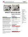
Product Specification
36502B
• Isochronous
speed control
APECS® DPG-21XX-00X
Digital Controllers
DESCRIPTION
The DPG-21XX-00X digital controller is
used primarily to govern diesel or gas
fueled engines of generator sets. This
microprocessor-based, digital controller
performs across a wide speed range and
allows adjustment of set speed and gain
parameters with the built-in user interface.
The COMM port provides access to all
other controller settings, allowing
adaptation to each application during
service and initial configuration.
Separately programmable Proportional,
Integral, and Derivative gains are provided
for tailoring controller response to many
engine applications. Other adjustments
include acceleration and deceleration
ramp rates, idle speed set, hold time,
and more.
Properly tuned, this controller delivers fast
engine response to speed or load change
while providing precise stable isochronous
operation.
The controller’s internal FAILSAFE reacts
instantly to loss of the engine speed
signal, allowing the actuator to return to
minimum fuel.
ACTUATOR
COMPATABILITY
DYNA 2000 DYNA 2500
• Precision
frequency control:
0.25%
• Superior
temperature
stability
• Reverse battery
protection
• Input voltage
range: 9–30 Vdc
DYNA 8000 DYNA 8200 DYNA 8400
• Smoke control on
start up
DYNA 10141
• Remote setup
APECS 0150 APECS 0250 APECS 0300
• Serial
communications
port
DYNA 7000 DYNA 70025
Power Flow Series Gas Valves
APECS Linkage Free Integral Type
OTHER MODELS
AVAILABLE
DPG-2200 Series – Load Sharing
Generator Applications
DPG-2300 Series – For Off-Road
Applications
DPG-2400 Series – EFC Valve
Applications
CALIBRATION TOOL
DPG Calibration Kit P/N 8447-1003
SPECIFICATIONS
DPG-21XX-00X controllers are compliant with applicable CE Directives—EMC. The controller’s main electrical
and mechanical specifications are listed here along with several performance characteristics.
DPG-21XX-00X Series controllers are available in five hardware configurations.
Configurations
Connector Style
Options
7-wire
12-pin
Euro
Molex
Model No.
Speed Sensing
Options
Magnetic
Ignition
Pickup
Sense
Adj.
Set
Speeds
DPG-2101-00X
*
*
1 + idle
DPG-2111-00X
*
*
1 + idle
*
DPG-2145-00X
DPG-2146-00X
DPG-2155-00X
*
*
*
2 + idle
*
1 + idle
*
Remote
Speed
INC and
DEC
2 + idle
*
*
Electrical
Operating Voltage Range:
Rated Output Current:
Maximum Surge Current:
Connections:
Input Signal from Magnetic Pickup:
Input Signal from Engine’s
Ignition System:
9–30 Vdc *
7 A Maximum (continuous)
14 A (not to exceed ten seconds)
Terminal strip with 7 Euro style terminals or a quick
connector with 12 pins
2.0 VAC RMS minimum during cranking
40 V minimum during cranking
(*) All cabling for these controllers is limited to less than 30m (98.4’).
Power cabling is limited to less than 10m (32.8’) in total length.
See wiring diagrams in User Manual 36526 for specific cable types required.
Mechanical
Ambient Operating Temperature:
-40°F to +185°F (-40°C to +85°C)
Sealing:
Oil, water, and dust resistant via conformal coating
and die cast enclosure
Weight:
10 oz. (284 g)
Performance
Steady State Speed Band:
Engine Speed MPU
Measurement Range:
Governing Speed Rangewith MPU:
Engine Speed Ignition
Measurement Range:
Governing Speed Range with Ignition:
± .25% over ambient operating temperature range
10 MPU Hertz to 14,000 MPU Hertz
500 MPU Hertz to 11,000 MPU Hertz
2 Hertz to 350 Hertz
25 Hertz to 300 Hertz
Suggested Mating Connectors for DPG-2145-00X and DPG-2155-00X Models
AMP 770581-1
AMP 171637-3 or 794407-3
AMP 90707-1
Mini universal Mate-N-Lock
Duplex finish socket
Crimping hand tool for 18 gauge wire
AMP 408-4137
Crimping documentation
AMP 189727-1
Socket extraction tool
PARAMETER REFERENCE
The parameter list provides information regarding each of the parameters that can be adjusted when a computer is
connected to the controller via the COMM port and Universal PST program. The COMM port and Universal PST are
intended only for configuration and periodic service. Do not leave a computer and/or COMM cable connected to
the COMM port.
The following table lists each of the parameters and their default, minimum, and maximum values. Several of the
parameters have minimum and maximum values set by other parameters. Speed and Rate values are shown as
Hertz values.
PARAMETER LIST FOR DPG-2101-00X (MPU) & DPG-2146-00X (IGNITION)
(These controllers use the 7-terminal Euro style screw terminal connector.)
PARAMETER NAME
DEFAULT
MINIMUM
MAXIMUM
-001
0
0
0
-002
0
0
572
1000 (25)
Set Speed A Min
Set Speed A Max
50 (20)
Idle Speed Min
Idle Speed Max
Opt.
1. No. of Flywheel Teeth
or (Pulses per revolution)
Req.
2. Set Speed A
Opt.
4. Idle Speed
Req.
5. Proportional
25
1
99
Req.
6. Integral
50
0
99
Req.
7. Derivative
25
0
99
Req.
8. OVG @ Set Speed A
3. Not Available
Use the controller’s built-in GAIN potentiometer
9. Not Available
Opt.
10. OVG @ Idle Speed
20
1
99
Req.
Req.
11. Gain Factor
20 (40)
1
99
12. Speed Filter
16 (4)
1
24
Opt.
13. Idle Hold Time
0
0
9999
Opt.
14. Accel Rate
1000 (3000)
1
9999
Opt.
15. Decel Rate
1000 (3000)
1
9999
Opt.
16. Startup Rate
1000 (3000)
1
9999
Opt.
17. Integral Low Limit
0
0
Integral High Limit
Opt.
18. Integral High Limit
99
Integral Low Limit
99
Opt.
19. Password
0
0
99
Opt.
20. Over Speed Limit
Opt.
21. Set Speed A Min
100
15000 (450)
10 (2)
0
0
10 (2)
100
15000 (450)
Set Speed A
Opt.
22. Set Speed A Max
11000 (300)
Set Speed A
11000 (300)
-001
-002
23. Not Available
24. Not Available
Opt.
25. Idle Speed Min
10 (2)
10 (2)
Idle Speed
Opt.
26. Idle Speed Max
11000 (300)
Idle Speed
11000 (300)
Opt.
27. Duty Cycle Limit
95
10
95
Opt.
28. Startup Speed
1000 (25)
10 (2)
11000 (300)
Opt.
29. Startup Duty Cycle
30
5
95
Req. = Parameter adjustment required to achieve Basic Governing
Opt. = Parameter use is optional
Default, Minimum and Maximum values in parenthesis apply when the controller uses ignition pulses to
sense engine speed, which would be the case for a DPG-2146-00X controller.
PARAMETER REFERENCE (Cont’d.)
The parameter list provides information regarding each of the parameters that can be adjusted when a computer is
connected to the controller via the COMM port and Universal PST program. The COMM port and Universal PST are
intended only for configuration and periodic service. Do not leave a computer and/or COMM cable connected to
the COMM port.
The following table lists each of the parameters and their default, minimum, and maximum values. Several of the
parameters have minimum and maximum values set by other parameters. Speed and Rate values are shown as
Hertz values.
PARAMETER LIST FOR DPG-2155-00X (MPU) & DPG-2145-00X (IGNITION)
(These controllers use the 12-terminal quick connect.)
PARAMETER NAME
Opt.
1. No. of Flywheel Teeth
or (Pulses per Revolution)
DEFAULT
MINIMUM
MAXIMUM
-001
0
0
0
-002
0
0
572
Req.
2. Set Speed A
1000 (25)
Set Speed A Min
Set Speed A Max
Opt.
3. Set Speed B
1000 (25)
Set Speed B Min
Set Speed B Max
Opt.
4. Idle Speed
50 (20)
Idle Speed Min
Idle Speed Max
Req.
5. Proportional
25
1
99
Req.
6. Integral
50
0
99
Req.
7. Derivative
25
0
99
Req.
8. OVG @ Set Speed A
Opt.
9. OVG @ Set Speed B
Use the controller’s built-in GAIN potentiometer
20
1
99
Opt.
10. OVG @ Idle Speed
20
1
99
Req.
11. Gain Factor
20 (40)
1
99
Req.
12. Speed Filter
16 (4)
1
24
Opt.
13. Idle Hold Time
0
0
9999
Opt.
14. Accel Rate
1000 (3000)
1
9999
Opt.
15. Decel Rate
1000 (3000)
1
9999
Opt.
16. Startup Rate
1000 (3000)
1
9999
Opt.
17. Integral Low Limit
0
0
Integral High Limit
Opt.
18. Integral High Limit
99
Integral Low Limit
99
Opt.
19. Password
0
0
0
10 (2)
99
100
15000 (450)
Set Speed A
Opt.
20. Over Speed Limit
Opt.
21. Set Speed A Min
0
100
15000 (450)
10 (2)
Opt.
22. Set Speed A Max
11000 (300)
Set Speed A
11000 (300)
Opt.
23. Set Speed B Min
10 (2)
10 (2)
Set Speed A
Opt.
24. Set Speed B Max
11000 (300)
Set Speed B
11000 (300)
Opt.
25. Idle Speed Min
10 (2)
10 (2)
Idle Speed
Opt.
26. Idle Speed Max
11000 (300)
Idle Speed
11000 (300)
Opt.
27. Duty Cycle Limit
Opt.
28. Startup Speed
Opt.
29. Startup Duty Cycle
-001
-002
95
10
95
1000 (25)
10 (2)
11000 (300)
30
5
95
Req. = Parameter adjustment required to achieve Basic Governing
Opt. = Parameter use is optional
Default, Minimum and Maximum values in parenthesis apply when the controller uses ignition pulses to
sense engine speed, which would be the case for a DPG-2145-00X controller.
PARAMETER REFERENCE (Cont’d.)
The parameter list provides information regarding each of the parameters that can be adjusted when a computer is
connected to the controller via the COMM port and Universal PST program. The COMM port and Universal PST are
intended only for configuration and periodic service. Do not leave a computer and/or COMM cable connected to
the COMM port.
The following table lists each of the parameters and their default, minimum, and maximum values. Several of the
parameters have minimum and maximum values set by other parameters. Speed and Rate values are shown as
Hertz values.
PARAMETER LIST FOR DPG-2111-00X
(These controllers use the 7-terminal Euro style screw terminal connector.)
PARAMETER NAME
-001
DEFAULT
MINIMUM
MAXIMUM
0
0
0
Opt.
1. No. of Flywheel Teeth
or (Pulses per Revolution)
Req.
2. Set Speed A
Opt.
3. Not Available
Opt.
4. Idle Speed
Req.
5. Proportional
25
1
99
Req.
6. Integral
50
0
99
Req.
7. Derivative
25
0
99
-002
0
0
572
1000
Set Speed A Min
Set Speed A Max
50
Idle Speed Min
Idle Speed Max
20
1
99
The controller’s built-in GAIN ADJUST potentiometer
provides a +/-20% adjustment range of the
nominal gain value entered.
Req.
8. OVG @ Set Speed A
Opt.
9. Not Available
Opt.
10. OVG @ Idle Speed
20
1
99
Req.
11. Gain Factor
20
1
99
Req.
12. Speed Filter
16
1
24
Opt.
13. Idle Hold Time
0
0
9999
Opt.
14. Accel Rate
1000
1
9999
Opt.
15. Decel Rate
1000
1
9999
Opt.
16. Startup Rate
1000
1
9999
Opt.
17. Integral Low Limit
0
0
Integral High Limit
Opt.
18. Integral High Limit
99
Integral Low Limit
99
Opt.
19. Password
0
0
0
10
99
100
15000
Set Speed A
Opt.
20. Over Speed Limit
Opt.
21. Set Speed A Min
0
100
15000
10
Opt.
22. Set Speed A Max
11000
Set Speed A
11000
Opt.
23. Not Available
Opt.
24. Not Available
Opt.
25. Idle Speed Min
10
10
Idle Speed
Opt.
26. Idle Speed Max
11000
Idle Speed
11000
Opt.
27. Duty Cycle Limit
95
10
95
Opt.
28. Startup Speed
1000
10
11000
Opt.
29. Startup Duty Cycle
30
5
95
-001
-002
Req. = Parameter adjustment required to achieve Basic Governing
Opt. = Parameter use is optional
PO Box 1519
Fort Collins CO, USA
80522-1519
1000 East Drake Road
Fort Collins CO 80525
Ph: +1 (970) 482-5811
Fax: +1 (970) 498-3058
Distributors & Service
Woodward has an
international network of
distributors and service
facilities. For your nearest
representative, call the
Fort Collins plant or see
the Worldwide Directory
on our website.
Corporate Headquarters
Rockford IL, USA
Ph: +1 (815) 877-7441
www.woodward.com
EUROPEAN COMPLIANCE FOR CE MARKING
EMC DIRECTIVE
Declared to 89/336/EEC COUNCIL DIRECTIVE of 03 May 1989 on the approximation of
the laws of the Member States relating to electromagnetic compatibility. See the
Declaration of Conformity in User Manual 36526.
EMC LIMITATIONS
Cabling
All cabling for this unit is limited to less than 30m (98.4’).
Power cabling is limited to less than 10m (32.8’) in total length from its source; power is
intended to be from a local bus structure. The control is not intended to have a power bus
that is derived from a plant-wide distribution system, remote source, or similar “mains”
type distribution systems. The power to the control should also be a dedicated circuit,
directly to the battery or source via a power and return wire that are routed together.
See User Manual 36526 for additional regulatory information, limitations, and wiring
diagrams with specific, required cable types.
Power Bus
The power bus is intended to be a local bus and to have inductive load kickback events
suppressed. Therefore, the control’s power input is not designed to withstand a charging
system load dump, heavy inductive kickbacks, or heavy surge type pulses. If the control is
installed outside its intended usage, as described in this manual, centralized voltage pulse
suppression should be implemented to protect the control and other components on the
bus. (See the installation instructions in User Manual 36526.)
COMM Port
The COMM port is intended to be a service port, with only temporary connection during
service or initial configuration. The COMM port is susceptible to some EMC phenomena
and possible unintentional battery return currents.
1. Battery return (B-) is also the communication signal common; typically PCs
connect the communication signal’s common to protective earth. The PC
grounding can provide an unintended return path for B- currents. If B- and the PC
are grounded to protective earth, a communication isolator should be used
between the PC and the control. Damage to the PC or control, and/or unintended
operation may result from a broken battery return wire or the parallel path.
2. The pins inside the COMM port plug are susceptible to damage by ESD
discharges, static electricity arcs. Care should be taken not to touch them with
tools or put fingers into the port. Always touch your hand or tool to a grounded
piece of metal (discharge ESD) before coming in contact with the COMM port.
3. The input is susceptible to RF noise such as switching transients and transmitter
signals coupled into the communication cable. Cable orientation and short cable
length may be used to eliminate these issues, depending on the severity of the
environment.
RELATED DOCUMENTATION
This document is distributed
for informational purposes
only. It is not to be construed
as creating or becoming part
of any Woodward Governor
Company contractual or
warranty obligation unless
expressly stated in a written
sales contract.
User Manual 36526
© Woodward 2006
All Rights Reserved
06/03/M
For more information contact: