1
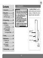
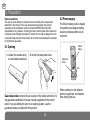
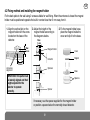
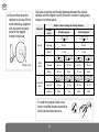
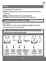
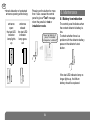
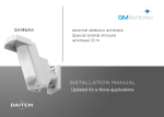
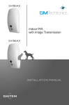
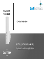
Updated for e-Nova applications
GB
Contents
1. Introduction
1. Introduction .................... 57
IMPORTANT
• Some functions are only available
with versions 2.0.0 or later (press
on
the control panel keypad to
check the version).
• The operating differences with
former ranges are described in
the compatibility booklet
available in the Daitem installers
section at www.daitem.co.uk.
2. Preparation ..................... 58
2.1 Opening...................... 58
2.2 Power supply ............. 58
3. Programming.................. 59
4. Installing.......................... 60
4.1 Choosing
the best place ............ 60
4.2 Fixing method
and installing
the magnet holder...... 61
The contact detector is used to
protect openings such as doors &
windows. It is fitted with a built-in
magnetic contact (reed switch).
LED indicator
lamp
5. Testing ............................. 63
Test button
6. Maintenance................... 64
6.1 Battery low
indication.................... 64
6.2 Changing
the battery .................. 65
Screw cover
Built-in
magnetic
contact
7. Technical data ................ 66
57
GB
2. Preparation
Recommendations
The user must not attempt to access the siren’s internal parts, except areas
described in this manual. If the user does access these parts, the product
guarantee will be considered null and void and DAITEM shall not be held
responsible for any problems. Touching the siren’s internal parts and/or electronic
components can damage the product. Furthermore, the siren is designed in such
a way that these parts and components do not need to be accessed for operation
or maintenance purposes.
2.2 Power supply
The lithium battery pack is clipped
into position (see diagram below).
An arrow indicates which way to
connect it.
Lithium
battery
2.1 Opening
1. Loosen the screws using
a cross-head screwdriver.
2. Unclip the base plate cover.
Alignment
arrow
LED
Guarantee sticker: remove the pre-cut part of the sticker and stick it to
the guarantee certificate in the user manual supplied with the control
panel. If you are adding the siren to an existing system, use the
guarantee sticker provided with this product.
58
When switched on the detector
performs a self-test: the indicator
lamp briefly lights up.
GB
3. Programming
During recognition
programming, the product to be
programmed for use with the
control panel does not need to
be placed next to it. In fact, we
recommend you place the
product at a short distance from
the control panel (at least
2 meters away).
Programming enables contact
detectors to be recognised by the
control panel.
1. To programme contact
detectors the control panel
must be in installation mode.
If it is not, you will require the
user’s master code, press:
master code
then press:
2. Programme the device as follows:
“detector X”
“group ?”
“time delay?”
“beep, detector X,
group Y,
immediate
(or delayed
or combined)”
)))
))
to
then
10 s max.
Press
‹ then #
on the
control panel
keypad
Press
and hold the
“test” button
until the control
panel responds
*
to
* according
to the type
of control panel
The control panel
waits for a group
to be chosen (from
1 to 8)*. Choose
the groups by
pressing the
corresponding
numeral on the
control panel
keypad
Choose the type
of triggering:
0: immediate
1: delayed
2: combined
Use the control
panel keypad
to select the type
The control
panel gives a
voice message
to confirm
detector
programming
IMPORTANT: the control panel indicates an error by emitting 3 short
beeps. When this happens programming should be carried out again.
engineer installer code
59
GB
• Example: programming of 1st detector allocated to Group 2 with immediate triggering.
“detector 1”
“group ?”
“time delay?”
“beep, detector 1
group 2,
immediate”
)))
))
then
10 s max.
4. Installing
IMPORTANT: make sure there is a distance of at least 2 meters between each product, except between 2
detectors.
4.1 Choosing the best place
The contact detector must be placed:
• inside the protected area,
• preferably on the door frame of the entrance to be protected at least 1 m above ground level,
• far away from any sources of interference (electricity meter, metallic frame, etc.),
• on a flat surface.
IMPORTANT: when the detector is fixed to a metal support, insert a 20 mm thick wooden or plastic spacer
between the base and the metal frame.
60
GB
4.2 Fixing method and installing the magnet holder
Fix the back plate to the wall using 2 screws suitable for wall fixing. When the entrance is closed the magnet
holder must be positioned opposite the built-in contact less than 5 mm away from it.
1. Align the vertical slot on the
magnet holder with the arrow
located on the base of the
detector.
2. Adjust the height of the
magnet holder according to
the diagrams below.
3. Fix the magnet holder base,
place the magnet inside the
cover and clip it to the base.
Max :
5 mm
Max :
5 mm
Magnet holder
Detector
Cover
Magnet
35 mm
slot-arrow
alignment
Spacers
Base
IMPORTANT: the parts must
be laterally aligned and their
height adjusted for the
detector to operate
correctly.
Spacers
Spacer
If necessary use the spacer supplied for the magnet holder
or position a spacer below the normally closed detector.
61
GB
Overview of opening and closing distances between the contact
detector and the magnet used by the built-in contact to analyse any
change in entrance status.
Built-in contact opening and closing distances
Movement
Contact
status
Wooden support
t
t
Spacing
opening
23 mm
22 mm
closing
11 mm
11 mm
Soft iron support
t
4. Clip and then screw the
detector to its base. Fit the
screw head plug (supplied
with the bunch of plastic
parts for the magnet
holder) to the cover.
t
t
24 mm
24 mm
19 mm
closing
20 mm
9 mm
15 mm
8 mm
opening
15 mm
12 mm
15 mm
12 mm
closing
9 mm
7 mm
8 mm
6 mm
To unclip the magnet holder cover,
insert a small flat-headed screwdriver
into the slot provided and turn.
62
t
34 mm
t
Horizontal
sliding
t
opening
2,5
t
Vertical
sliding
t
Screw cover
GB
5. Testing
The contact detector has a “test” mode for testing:
• the battery: the LED indicator lamp lights up when the test button is pressed to indicate the battery is
working correctly,
• detection: the LED indicator lamp lights up when the contact changes status,
• the radio link: see § on Checking the radio links described in the control panel manual.
IMPORTANT: the control panel must be in installation mode for testing.
To test the detector:
• press the test button and the detector changes to test mode for about 90 sec. After this period the
detector automatically returns to normal operating mode,
!
In accordance with the new functional requirements of EN50131-2-6, the LED is factory defaulted to be
Inactive in Test Mode. To change this parameter, programme:
about 10 sec.
Commence
the sequence
by pressing the
test button until
the LED is off.
2
Press 2 times
depending
on the required
parameter number.
about
5 sec.
Press and hold
and then release the
test button as soon
as the LED lights
for the 2nd time.
1 or 2
Press the test 1 or 2
times to select the
required parameter.
• 1: inactive
• 2: active.
63
about 10 sec.
Finish the
programming
by pressing the test
button until the led
is off.
about
2 sec.
LED lights for 2
seconds to
confirm valid
programming.
GB
• check detection of protected
entrance opening and closing:
entrance
open:
the test LED
indicator
lamp lights
up
entrance
closed:
the test LED
indicator
lamp goes
out
Pressing on the button for more
than 1 sec. causes the control
panel to give a “Test” message
when the panel is in test or
installation mode.
“beep, test detector X,
group Y immediate
(or delayed or combined)”
)))
))
6. Maintenance
6.1 Battery low indication
The control panel indicates when
the contact detector’s battery is
low.
To check whether there is a
problem with the detector battery,
press on the detector’s test
button.
If the test LED indicator lamp no
longer lights up, the lithium
battery should be replaced.
64
GB
6.2 Changing the battery
To change the battery:
1. switch the control panel to installation mode and ask the master user to press:
then press:
master code
engineer installer code
2. open the detector casing (see § on Opening),
3. unclip the lithium battery pack,
4. wait 2 min. before replacing the flat lithium battery,
5. close the detector,
6. switch the control panel back to user mode, press:
IMPORTANT: the detector’s
configuration is saved when the
battery is changed.
engineer installer code
• The lithium battery pack must be replaced by the same type of pack with the same technical characteristics,
i.e. (3 V).
• We advise you to use the DAITEM BatLi31 pack available in the catalogue in order to guarantee
Li
individual safety and equipment reliability.
• Dispose of the waste lithium power pack in an appropriate recycling bin.
Waste processing of electrical and electronic devices at the end of their service life (Applicable in European
Union countries and other European countries with a waste collection system). Used on products or product
packaging, this symbol indicates that the product must not be thrown out with household waste. It must be taken
to a waste collection point for electrical and electronic product recycling. When you make sure that this product
is disposed of in the most appropriate manner, you are helping to protect the environment and human health. If you
would like additional information concerning the recycling of this product, please contact your town/city council, nearest waste collection centre or the shop where you bought the product.
65
GB
7. Technical data
Specifications
Built-in magnetic contact
1
Contact detector
Environment
building interior
Power supply
DAITEM lithium battery (BatLi31 - 3 V)
Battery life
5 years in normal conditions of use
Radio links
TwinBand® 400/800 MHz
Test button
programming, battery and detection test
LED Indicator lamp
1
Operating temperature
-10 °C to +55 °C
Anti-tamper & protection
• against opening and removal
• against loop cutting
Degrees of mechanical protection
IP 31/IK 04
Dimensions L x W x H
108 x 26 x 30 mm
Weight (with battery)
60 g
66
GB
To obtain advice when installing your
system or before returning equipment,
please contact the Daitem technical
support team (see telephone number at
the back of the alarm system installation
manual) or check the web site at:
www.daitem.co.uk
A team of qualified technicians will
advise you what to do.
DECLARATION OF CONFORMITy
13
Manufacturer: Hager Security SAS
Address: F-38926 Crolles Cedex - France
Product type: Contact detector
Trade mark: Daitem
We declare under our sole responsibility that the product to which this declaration relates
is compliant with the essential requirements of the following directives:
• R&TTE Directive: 99/5/EEC
• Low voltage directive: 2006/95/EC
• Directive ROHS: 2002/95/EC
in compliance with the following harmonised European standards:
Products code
EN 300 220-2 V2.3.1
EN 50130-4 (95) + A1 (98) + A2 (2002)
EN 55022 & 55024 (2002)
EN 60950 (2006)
EN 301 489-1 V1.8.1
SH273AX
X
X
X
X
X
SH274AX
X
X
X
X
X
This product can be used in all EU, EEA Countries and Switzerland.
Crolles, 08.04.2013
Signature: Patrick Bernard
Director of Research and Development
Non-contractual document, may be modified without prior notice.
67
805350/A - 04.2013