1
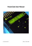
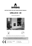
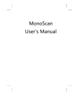
Indoor PIR
with Image Transmission
GB
Contents
1. Introduction..................................................................................... 93
2. Preparation...................................................................................... 95
3. Recognition programming ............................................................ 97
3.1 Programming for recognition by the control panel ................... 97
3.2 Programming for recognition by the standalone dialler............ 99
4. Parameter-setting ........................................................................ 101
4.1 Setting the parameters of detector SH195AX......................... 101
4.2 Setting the parameters of detector SH196AX......................... 101
4.3 Parameter-setting procedure................................................... 102
5. Installing the detector.................................................................. 103
5.1 Choosing the best place.......................................................... 103
5.2 Fixing the detector in place ..................................................... 105
6. Testing operation.......................................................................... 105
6.1 Testing infrared detection......................................................... 105
6.2 Testing the radio link ................................................................ 105
6.3 Testing SH196AX detector non-detection of pets .................. 106
6.4 Testing the optical field in the daytime
or in low lighting conditions ..................................................... 106
7. Maintenance ................................................................................. 107
7.1 Fault indications ....................................................................... 107
7.2 Changing the battery ............................................................... 107
8. Technical data............................................................................... 109
Recommendations
The user must not attempt to access the detector’s internal parts, except areas
described in this manual. If the user does access these parts, the product guarantee
will be considered null and void and DAITEM shall not be held responsible for any
problems. Touching the detector’s internal parts and/or electronic components can
damage the product. Furthermore, the detector is designed in such a way that these
parts and components do not need to be accessed for operation or maintenance
purposes.
92
GB
1. Introduction
IMPORTANT
• Some functions are only available with control panel version 2.0.0
or later (enter
) on the control panel
keypad to check the version).
• Operating differences with respect to former ranges are described
in the compatibility booklet available in the Daitem Installers section
at www.daitem.co.uk.
The motion detector with image transmission SH195AX or SH196AX (pettolerant) provides:
• protection against intrusion in the home,
• recording of a sequence of images if an alarm is triggered,
• transmission of a sequence of images when intrusion occurs, via the
GSM/GPRS and/or ADSL standalone dialler (or a control panel fitted
with an ADSL or GSM/GPRS transmission module).
The SH196AX pet-tolerant motion detector monitors the interior of a room
and is able to distinguish between the presence of a human being and
that of a pet (cat, dog, etc.). The detector can be used for pets whose
weight does not exceed 25 kg and according to their type of coat (see
table below).
Animal coat
Weight (W)
More than 25 kg
Long hair
Medium
length/wire hair
Short hair
detector
detector
detector
cannot be used cannot be used cannot be used
20 kg < W < 25 kg
detector
can be used
detector
detector
cannot be used cannot be used
12 kg < W < 20 kg
detector
can be used
detector
can be used
detector
cannot be used
Below 12 kg
detector
can be used
detector
can be used
detector
can be used
IMPORTANT: if there are several animals in the same room, it is their
total weight that must be taken into account according to the table
above.
93
GB
If intrusion occurs and the control panel is armed:
• the alarm system is triggered via the control panel,
• a sequence of 10-second images is recorded by the camera built into
the detector. Its built-in flash ensures visibility even in low lighting
conditions.
The microSD card stores the last 10 image sequences.
The recorded image sequences can be retrieved and viewed by
inserting the microSD card into a computer drive (Windows SP2
minimum required - not compatible with other operating systems such
as Mac OS X, Linux, etc.).
• and if the system is fitted with a GSM/GPRS and/or ADSL standalone
dialler (or a control panel fitted with a GSM/GPRS and/or ADSL
transmission module), the motion detector transmits the recorded
image sequence via TwinBand® radio to the dialler (or to the control
panel transmission module).
This image sequence is remotely sent by the standalone dialler (or by
the control panel fitted with a transmission module) for immediate
image/video confirmation of intrusion to:
- a remote monitoring centre,
- a mobile phone in MMS format.
On receipt of the sequence it is possible to visually check what has
really happened on the premises where the alarm was triggered as soon
as the information is received.
When the system is fitted with a standalone dialler powered by the
mains (or if the control panel is fitted with a transmission module
powered by the mains), you can ask to view an image sequence via
your computer or Smartphone (iPhone/Android) when there is no
intrusion.
This feature can be accessed by the system user once the installer has
created a customer account via the secure Internet Portal dedicated to
Daitem system use when this becomes available (accessed via
http://www.daitem.co.uk.
When this request is received via the Portal, the detector’s response is
similar to when an intrusion occurs, i.e. it records an image sequence on
the microSD card and transmits this but without any alarm information.
The sequences of images recorded or transmitted are date and timestamped. The date and time are automatically updated by the control
panel (the control panel date and time must be correct).
94
GB
If a drop in temperature is detected (below 5°C), telephone transmission
to correspondents is activated 24 hours a day.
The detector is factory set not to detect below freezing temperatures (see
chapter “4. Parameter-setting”).
Front view
¿ Test button.
¡ Detection lens.
¬ Test LED (behind lens).
√ MicroSD card (supplied) compartment.
ƒ Night lighting flash.
≈ Removable cover.
∆ Camera.
¿
¡
¬
∆
√
ƒ ≈
The infrared detection
protects rooms at risk (living
room, parents’ bedroom,
etc.) according to a 90°
angle over a distance of
12 m.
The infrared detection zone
is identical to the optical
field zone (camera).
The optical field
corresponds to the view of
the built-in camera
according to an angle of 90°
with a range of up to 12 m.
IMPORTANT: when images
are recorded in the dark,
the range of the built-in
flash is limited to 7 m
maximum.
95
GB
2. Preparation
Opening the detector
1. Unclip the cover at the side
in order to remove it.
¬
cover
2. Loosen the locking screw
using a Philips screwdriver
and open the box.
¿
t
3. Remove the protective film
from the lens.
¡
Pozidriv 2
Power supply
Position the lithium power pack supplied in its
compartment making sure it is the right way
round. The red LED behind the lens lights up for
roughly 2 s (it is normal for the red LED to
constantly flash when the detector is not clipped
on to its base).
196-21X
Coller sur certif
A1142A047879
196-21X
Coller sur certif
A1142A047879
t
Guarantee sticker
Remove the pre-cut part of the sticker and
stick it to the guarantee certificate inside the
user manual supplied with the control panel. If
you are adding to an existing system, use the
guarantee certificate supplied with this
product.
lithium
power
pack
SH196AX
Coller sur certif
A1142A047879
IMPORTANT
• If the red LED does not light up when the power pack is
connected, check the pack is properly positioned.
• If the red LED flashes very quickly when the pack is connected,
check the lithium battery reference (BatLi30) as well as its date
of manufacture, which must be 10/2012 or later.
96
GB
IMPORTANT: if there is no microSD card inserted
or it is not recognised by the motion detector,
image sequences can no longer be recorded but
they can be transmitted.
4GB
Inserting the microSD card
Insert the microSD card into its compartment
making sure it is the right way round:
• if the microSD card is recognised, the red LED
behind the lens lights up for roughly 1 s.
• if the microSD card is not recognised, the red
LED behind the lens flashes 3 times. Check the
card is inserted the right way round and start
again.
microSD card
compartment
3. Recognition programming
Image transmission motion detectors must be programmed for
recognition either by:
• the control panel (intrusion event management)
• the control panel fitted with the transmission module (intrusion event
management and image transmission).
For the transmission of image sequences via a standalone dialler, the
detector must first be programmed for recognition by the control panel
(intrusion event management) and then by the standalone dialler (image
transmission).
3.1 Programming for recognition by the control panel
Recognition programming enables the detector to be recognised by the
control panel as well as images to be transmitted if the control panel
is fitted with a transmission module.
The image sequences are recorded on the microSD card even if the
control panel is not fitted with a transmission module or if the installation
does not have a standalone dialler.
97
GB
IMPORTANT
• During recognition programming, the detector does not need to be
placed close to the control panel. In fact, we advise you to place it at
least 2 metres away.
• The detector must be programmed for immediate triggering
for image sequences to be recorded and transmitted when intrusion
occurs.
1. To perform detector recognition programming, the control panel
must be in installation mode. If it is not, ask the user to enter:
“beep,
installation mode”
master code (factory: 0000)
then
installer code (factory: 1111)
2. Perform the following recognition programming sequence:
“detector X”
“group”
“time delay?”
“beep,
detector X,
group Y,
immediate”
)))
))
to
then
10 s max.
Press ‹ then
# on the
control panel
keypad
Press and hold
the “test”
button until the
control panel
responds
Select a group
from 1 to 8.
Use the
control panel
keypad to do
this.
Programme the
detector for
immediate
triggering.
Use the control
panel keypad
to do this.
The
control panel
confirms
recognition
programming
and the red
LED on the
detector lights
up twice
for 2 s.
The control panel issues three short beeps to indicate a
programming error. When this happens, perform programming
again from the start.
98
GB
3. Check recognition programming. Press the test button on the
detector until the control panel issues the voice message
corresponding to the selected programming.
))
“beep, test detector X,
group Y, immediate”
)))
IMPORTANT: if, at a later date, the control panel is fitted with a
transmission module, detector/control panel recognition programming
must be performed again for the image sequences to be transmitted.
3.2 Programming for recognition by the standalone dialler
For image sequence transmission via a standalone dialler, the detector
must be programmed for recognition by the dialler.
IMPORTANT
• Image transmission motion detectors must be programmed for
recognition by the control panel (intrusion event management) and
the standalone dialler (image transmission).
• Programming image transmission motion detectors (up to 40) to be
recognised by the dialler is only possible if the alarm control panel
has been programmed for recognition by the dialler.
• The number is automatically allocated by the dialler during
recognition programming. For example, the same detector cannot be
programmed for recognition by the control panel as number 10 and
programmed for recognition by the dialler as number 6.
• To perform recognition programming operations, the dialler must be
in installation mode. When powered, the dialler is in installation mode.
If a control panel has been programmed for recognition by the dialler,
the dialler switches to the same mode as the control panel after 4 h
with no order being issued and automatically enters user mode.
99
GB
1. To perform detector recognition programming, the dialler must be
in installation mode. If it is not, ask the user to enter:
“beep,
installation mode”
master code (factory: 0000)
then
installer code (factory: 1111)
DIALLER
2. Perform the following recognition programming sequence:
“detector X”
DIALLER
))
)))
DIALLER
then
10 s max.
Press ‹ then #
on the dialler
keypad
Press and hold the
“test” button until the
dialler responds
The dialler issues
a voice message to
confirm detector
recognition
programming.
The red LED on
the detector
lights up twice
for 2 s.
• The dialler issues three short beeps to indicate a programming
error. When this happens, perform programming again from the
start by placing the unit approximately 2 m from the transmitter.
• If recognition programming repeatedly fails, proceed as follows:
1. disconnect the power supply from the alarm control panel as
well as the radio repeater relay(s) if there are any in the
installation,
2. perform recognition programming again,
3. after “learning-in” re-apply power to the alarm control panel
and any radio relay units.
3. Check recognition programming. Press and hold the “test” button
on the detector until the dialler responds.
))
)))
“beeep, beep, detector X”
100
GB
4. Parameter-setting
IMPORTANT: detector parameter-setting must only be performed with
the detector cover open.
4.1 Setting the parameters of detector SH195AX
Function
description
Parameter Parameter
value
n°
1
Detection
sensitivity
1
Test LED
lighting (1)
2
Alarm level
4
Image sequence
on request (2)
6
Above freezing
temperature
7
2
1
2
1
2
3
4
1
2
1
2
Characteristics
Beam crossed a first time: not recommended
Beam crossed a second time (factory
configuration): recommended
Deactivated (factory configuration)
Activated
Intrusion (factory configuration)
Prealarm
Deterrence
Warning
Authorisation activated (factory configuration)
Authorisation deactivated
Detection deactivated (factory configuration)
Detection activated
4.2 Setting the parameters of detector SH196AX
Function
description
Parameter Parameter
value
n°
Test LED
lighting (1)
2
Sensitivity level
setting
3
Alarm level
4
Image sequence
on request (2)
6
Above freezing
temperature
7
1
2
1
2
3
4
1
2
3
4
1
2
1
2
Characteristics
Deactivated (factory configuration)
Activated
Level 1: standard sensitivity
(factory configuration)
Level 2: average sensitivity
Level 3: high sensitivity
Level 4: maximum sensitivity
Intrusion (factory configuration)
Prealarm
Deterrence
Warning
Authorisation activated (factory configuration)
Authorisation deactivated
Detection deactivated (factory configuration)
Detection activated
(1) The infrared detector has a test mode for testing the detection zone:
• press the test button and the detector switches to test mode for 90 seconds,
• each detection is indicated by the LED lighting up.
(2) Image transmission request via Daitem user Portal (when no intrusion has occurred).
101
GB
Sensitivity level setting
In most cases, level 1 (factory configuration) and compliance with
installation rules ensure that the room is properly protected and that
pets do not trigger the system.
However, depending on the pet and the configuration of the room,
the detector’s level of sensitivity can be modified so that it has pet
detection zones and pet non-detection zones.
Set according to graph below:
IMPORTANT: the smaller the
pet, the higher the sensitivity
level can be.
Size of pet
Large
Small
Sensitivity
level
Level 1
Level 2
Level 3
Level 4
4.3 Parameter-setting procedure
Perform the parameter-setting procedure described below:
roughly 10 s
To start
the sequence,
press and hold
the button
until the LED
goes out.
1, 2, 3, 4,
6 or 7
roughly
5s
1 to 4
Press
the button
1, 2, 3, 4, 6
or 7 times
to select the
parameter.
Press and
hold the
button until
the LED
goes out
and then
lights up
again.
Press
the button
1 to 4 times
according
to the
chosen
parameter
value.
102
roughly 10 s
To end
the sequence,
press and hold
the button
until the LED
goes out.
roughly 2 s
LED
steadily
lit =
programming
confirmed
GB
5. Installing the detector
IMPORTANT
• Make sure there is a distance of at least 2 metres between each
product, except between two detectors.
• Point the detector in the right direction using the swivel bracket
provided and so that the camera is monitoring the entrances to be
protected.
5.1 Choosing the best place
The motion detector must be placed:
• inside the home,
• at a height of roughly 2.2 m,
• at right angles to the entrances to be protected (interior detection works
best when the intruder walks across the detector’s field-of-view),
• in such a way that the area it protects does not overlap with that of
another motion detector.
The motion detector must not be placed:
• opposite or above a surface likely to heat up quickly (e.g. fireplace),
• opposite a bay window,
• pointing towards the sun or reflective surfaces (floor, tiles, mirror, etc.)
as the images picked up by the camera would be overexposed (white),
• pointing towards a moving object (curtains, blinds, etc.),
• pointing towards the outside of the home or placed in a draught,
• directly on to a metal wall or
close to sources of interference
(electricity meters, etc.)
• opposite stairs accessible to
pets so that it does not detect
these pets in the detection
zones (concerns SH196AX).
RIGHT
WRONG
RIGHT
WRONG
103
GB
Detection zones for pet-tolerant detector SH196AX
Detection zone for pets weighing less
than 6 kg
pets must not enter this zone
Detection zone for pets weighing more
than 6 kg
pets are allowed to enter this zone
Depending on the room and/or pet, the fixing height (measured
from the centre of the detector lens) can be adjusted. When the
detector is not fixed at a height of 2.2 m from the ground, the limit
between the detection zone and the non-detection zone can vary.
5.2 Fixing the device in place
1. Position the
Mount accessories
back-plate on
in this order
the wall in the
chosen
Pozidriv 1
location, mark
the position of
the screws and
drill the holes in
the wall.
2. Insert a longbase
stemmed screw
via the rear of
screw +
tightening
the back-plate
washer
and fix the
longswivel bracket
back-plate.
stemmed
screw
3. Position the
back-plate back-plate cover
back-plate
cover.
4. Assemble the two parts of the swivel bracket.
5. Insert the assembled swivel bracket into the long-stemmed screw.
6. Position the motion detector base.
7. Tighten the locking screw just enough to be still able to adjust detector
orientation.
8. Position the motion detector on its base and point it in roughly the right
direction.
9. Retighten the locking screw.
104
GB
6. Testing operation
IMPORTANT: it is normal for the red LED to constantly flash when the
detector is not clipped on to its base.
6.1 Testing infrared detection
Briefly press the detector test button (< 1 s) to check the detection zone
and the radio link: with each detection, the control panel issues the voice
message “beep, intrusion detector X”.
))
“beep,
intrusion, detector X”
)))
6.2 Testing the radio link
This test is to be performed with the device used for image
transmission, i.e.:
• either a standalone dialler,
• or a control panel fitted with a transmission module.
We advise you to test the radio link for each image transmission detector.
It is advisable to move at least 2 m away from the transmission device in
order to do this. To ensure radio link reliability over time, each radio link
must be carefully checked once all the products have been installed.
Proceed as follows:
1. Transmission
device(*) in
installation
mode.
2. Briefly press the detector test
button. The detector LED lights
up for 2 s and then lights up again
at the end of the test.
3. The transmission device (*) performs the test:
• the test is positive:
- the transmission device (*) issues a long beep,
- the detector LED lights up once for 2 s,
• the test is negative:
- the transmission device (*) issues 3 short beeps,
- the detector LED flashes 3 times.
(*) either the GSM/GPRS and/or ADSL standalone dialler, or the control panel fitted
with the GSM/GPRS and/or ADSL transmission module.
105
GB
6.3 Testing SH196AX detector non-detection of pets
Let your pet move around in the room to check detector non-detection
(control panel: no vocal notification).
Detection occurs
the 2nd time the
beam is crossed
Detection zone
for a human being
2,2 m
h
0
d
12 m
For example, with a level 1 sensitivity setting, when the detector is
fixed at a height of 2.2 m, a 1.7 m tall human being is detected as of
4 m (d). The higher the sensitivity level, the shorter distance “d” at
which a human being is detected.
6.4 Testing the optical field in the daytime or in low lighting
conditions
It is important to make sure that the optical field test works. If it does not,
loosen the screw and tightening washer and adjust detector orientation.
NOTE / Flash activation: during the optical field test in low lighting
conditions, the flash lights up so that image sequences can be
recorded up to a distance of 7 metres.
1. Briefly press the detector test button twice until the red LED flashes
rapidly behind the lens.
2. Move in front of the detector until the LED goes out.
optical field zone
106
GB
3. Check the sequences:
• recorded by reading the microSD card (see User guide),
• transmitted via the standalone dialler (or by the control panel fitted
with a transmission module).
4. If the optical field test does not work:
• check there are no obstacles in the way of the detection zone,
• loosen the screw and tightening washer in order modify detector
orientation.
5. Put the control panel back in user mode using the keypad to enter:
“beep,
disarmed”
installer code
6. Perform a real test.
7. Maintenance
7.1 Fault indications
The control panel constantly monitors detector status. Depending on the
fault, it issues a voice message when the system is disarmed or armed as
indicated in the table below:
Message issued by the control panel
Cause
“beep, fault, detector X”
no microSD card inserted or
card not recognised or faulty(*)
“beep, fault, tamper, detector X”
detector not properly clipped
on to base
“beep, fault, voltage, detector X”
lithium battery low
“beep fault, radio link, detector X”
radio link between detector
and control panel faulty
(*) check there is a micro SD card present and whether it is properly inserted.
7.2 Changing the battery
The control panel indicates a detector battery fault by
issuing the voice message “fault, voltage, detector X”.
To check whether the detector lithium power pack is faulty,
press the detector test button.
IMPORTANT: if the red LED does not light up when the test
button is pressed, the lithium power pack needs replacing.
107
GB
To change the battery:
1. Put the control panel in installation mode by asking the user to enter:
master code
“beep,
installation mode”
then
installer code
IMPORTANT
• To remain functional, the detector must be powered by a BatLi30
lithium power pack whose date of manufacture is 10/2012 or later.
• Detector programming is saved when the lithium power pack is
changed.
2. Loosen the locking screw to open the detector.
3. Unclip the lithium power pack.
4. Wait for 2 min before replacing the flat lithium power pack.
5. Close the detector and tighten the locking screw.
6. Press the test button and check the detection zone and optical field.
7. Put the control panel back in user mode using the control panel
keypad or a remote keypad to enter:
“beep,
disarmed”
installer code
• The lithium power pack must be replaced with the same type of pack
offering the same characteristics, i.e. 4.5 V – 3 Ah.
• We advise you to use a DAITEM BatLi30 power pack available in the
catalogue in order to guarantee equipment reliability and individual
safety.
• Dispose of the flat power pack in a lithium battery
Li
recycling bin.
108
GB
8. Technical data
Technical specifications
Motion detector
with image transmission
Infrared detection
• SH195AX: volumetric, 12 m, 90°
• SH196AX: volumetric, 12 m, 85°
Optical field
12 m, 90°
Storage capacity
the last 10 sequences lasting 10 s
Film format for microSD card
• 640 x 480 colour VGA
reading on a computer (following • 10-second image sequences
intrusion or on request to view
with 3 images/second
images)
MMS image format
• 320 x 240 colour JPEG
• 10-second image sequence
Remote monitoring centre film
format
10-second film with 1 image/second
Flash range
up to 7 m at 0 lux
Type of fixing
on swivel bracket
Use
indoor
Power supply
BatLi30 lithium power pack - 4.5 V - 3 Ah
(manufactured on 10/2012 or later)
Battery life
5 years: 5 image transmissions (intrusion)
per year + 10 image sequence
requests per month
LED
1
Operating temperature
0°C to + 55°C
Anti-tamper protection
against opening
Average humidity rate
from 5% to 75% without condensation
at 25°C
Degrees of mechanical protection IP 31/ IK 04
Dimensions without swivel
bracket
67 x 52 x 128 mm
Weight
325 g (with lithium battery, swivel bracket
and back-plate)
109
DÉCLARATION DE CONFORMITÉ
FR
Fabricant : Hager Security SAS
13
Adresse : F-38926 Crolles Cedex - France
Type de produit : Détecteur de mouvement
Marque : Daitem
Nous déclarons sous notre seule responsabilité que les produits auxquels se réfèrent
cette déclaration sont conformes aux exigences essentielles des directives suivantes :
• Directive R&TTE : 99/5/CE
• Directive Basse Tension : 2006/95/CE
• Directive ROHS : 2002/95/CE
conformément aux normes européennes harmonisées suivantes :
Référence produit
EN 300 220-2 V2.3.1
EN 50130-4 (2011)
EN 60950-1 (2006)
EN 301 489-1 V1.8.1
SH195AX
X
X
X
X
SH196AX
X
X
X
X
Ces produits peuvent être utilisés dans toute l’UE, l’EEA et la Suisse
Crolles, le 02.01.2013
Signature :
Patrick Bernard
Directeur Recherche et Développement
Document non contractuel soumis à modifications sans préavis.
DICHIARAZIONE DI CONFORMITÀ
IT
Fabbricante: Hager Security SAS
13
Indirizzo: F-38926 Crolles Cedex - France
Tipo di prodotto: Rivelatore di movimento
Modello depositato: Daitem
Dichiariamo sotto la nostra responsabilità che i prodotti cui questa dichiarazione
si riferisce sono conformi ai requisiti essenziali delle seguenti Direttive Europee:
• Direttiva R&TTE: 99/5/CE
• Direttiva Bassa Tensione: 2006/95/CE
• Direttiva ROHS: 2002/95/CE
in ottemperanza alle seguenti Normative Europee armonizzate:
Codice dei prodotti
EN 300 220-2 V2.3.1
EN 50130-4 (2011)
EN 60950-1 (2006)
EN 301 489-1 V1.8.1
SH195AX
X
X
X
X
SH196AX
X
X
X
X
Questi prodotti possono essere utilizzati in tutta l’UE, i paesi di EEA, Svizzera.
Crolles, 02.01.2013
Firmato:
Patrick Bernard
Direttore Ricerca e Sviluppo
Documento non contrattuale, può essere soggetto a modifiche senza preavviso.
110
KONFORMITÄTSERKLÄRUNG
DE
Hersteller: Hager Security SAS
13
Adresse: F-38926 Crolles Cedex - France
Gerätetyp: IR Bewegungsmelder mit Kamera innen
Marke: Daitem
Diese Produkte entsprechen den grundsätzlichen Anforderungen der folgenden
europäischen Richtlinien, und zwar:
• Richtlinie R&TTE: 99/5/EG
• Niederspannungsrichtlinie: 2006/95/CE
• Richtlinie ROHS: 2002/95/CE
konform mit folgenden europäischen harmonisieren Normen:
Produktreferenz
EN 300 220-2 V2.3.1
EN 50130-4 (2011)
EN 60950-1 (2006)
EN 301 489-1 V1.8.1
SH195AX
X
X
X
X
SH196AX
X
X
X
X
Dieses Produkt darf in der EU, dem EWR und der Schweiz betrieben werden.
Crolles, den 02.01.2013
Unterschrift:
Patrick Bernard
Leiter Forschung & Entwicklung
Hinweis: Änderungen der technischen Daten und des Designs aufgrund von
Produktverbesserungen bleiben uns ohne Ankündigung vorbehalten. Nachdruck, auch
auszugsweise, nur mit ausdrücklicher Genehmigung des Herstellers.
DECLARACION DE CONFORMIDAD
ES
Fabricante: Hager Security SAS
13
Dirección: F-38926 Crolles Cedex - Francia
Tipo de producto: Sensor de movimiento
Marca: Daitem
Declaramos bajo nuestra sola responsabilidad que los productos a los cuales
se refiere esta declaración son conformes con las exigencias esenciales
de las directivas siguientes:
• Directiva R&TTE: 99/5/CE
• Directiva Baja Tensión: 2006/95/CE
• Directiva ROHS: 2002/95/CE
de conformidad con las normas europeas armonizadas siguientes:
Referencia del producto
EN 300 220-2 V2.3.1
EN 50130-4 (2011)
EN 60950-1 (2006)
EN 301 489-1 V1.8.1
SH195AX
X
X
X
X
SH196AX
X
X
X
X
Estos productos pueden ser utilizados en toda la UE, la EEA y Suiza.
Crolles, el 02.01.2013
Firma:
Patrick Bernard
Director Investigación y Desarrollo
Documento no contractual sometido a modificaciones sin aviso previo.
111
GELIJKVORMIGHEIDSVERKLARING
NL
Fabrikant: Hager Security SAS
13
Adres: F-38926 Crolles Cedex - France
Soort product: Bewegingsdetector
Merk: Daitem
We verklaren op eigen verantwoordelijkheid dat de producten, waarop deze
gelijkvormigheidsverklaring betrekking heeft, beantwoorden aan de fundamentele
voorschriften van de volgende richtlijnen:
• Richtlijn R&TTE: 99/5/CE
• Richtlijn Laagspanning: 2006/95/CE
• Richtlijn ROHS: 2002/95/CE
conform met de volgende geharmoniseerde Europese normen:
Productreferentie
EN 300 220-2 V2.3.1
EN 50130-4 (2011)
EN 60950-1 (2006)
EN 301 489-1 V1.8.1
SH195AX
X
X
X
X
SH196AX
X
X
X
X
Deze producten mogen gebruikt worden in de Europese Unie,
de EEZ en in Zwitserland.
Crolles, op 02.01.2013
Handtekening: Patrick Bernard, Directeur Research & Ontwikkeling
Niet-contractueel document onderworpen aan wijzigingen zonder voorafgaande
kennisgeving.
DECLARATION OF CONFORMITY
GB
Manufacturer: Hager Security SAS
13
Address: F-38926 Crolles Cedex - France
Product type: Motion detector with image transmission
Trade mark: Daitem
We declare under our sole responsibility that the product to which this declaration relates
is compliant with the essential requirements of the following directives:
• R&TTE Directive: 99/5/EEC
• Low voltage directive: 2006/95/EC
• Directive ROHS: 2002/95/EC
in compliance with the following harmonised European standards:
Products code
EN 300 220-2 V2.3.1
EN 50130-4 (2011)
EN 60950-1 (2006)
EN 301 489-1 V1.8.1
SH195AX
X
X
X
X
This product can be used in all EU, EEA Countries and Switzerland.
Crolles, 02.01.2013
Signature:
Patrick Bernard
Director of Research and Development
Non-binding document, may be modified without prior notice.
112
SH196AX
X
X
X
X
113
114
115
805295/B - 07.2013