1
User’s
Manual
Model SC100
Panel Mount Conductivity Converter
IM 12D11A01-01E
IM 12D11A01-01E
1st Edition
Safety Precautions
r Introduction
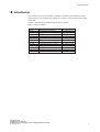
This manual covers the specifications, installation, operation and maintenance of the
panel-mount version of the SC100 Conductivity converter. Please read this before using
the SC100.
There are manuals for the related EXA100 series as follows:
Refer to them as required.
Model code
PH100
Manual Name
Panel Mount pH Converter
IM No.
IM 12 B11A01-01E
OR100
SC100
PH10FP
PH10RP
Panel Mount ORP Converter
Panel Mount Conductivity Converter
KCl Refillable pH Sensor
KCl Replenish-free pH Sensor
IM 12 C11A01-01E
IM 12 D11A01-01E
IM 12 B11C01-01E
IM 12 B11C02-01E
OR10FP
OR10RP
SC10XB
KCl Refillable ORP Sensor
KCl Replenish-free ORP Sensor
Conductivity Sensor for SC100
IM 12 C11C01-01E
IM 12 C11C02-01E
IM 12 D11C01-01E
WTB100
WF100
PH10HLD
PH10HG
Terminal Box for EXA100
Extension Cable for EXA100
Immersion Holder for EXA100
Guide-pipe Holder for EXA100
IM 12 B11E01-01E
IM 12 B11F01-01E
IM 12 B11D01-01E
IM 12 B11D02-01E
T000.eps
IM 12D11A01-01E
1st Edition: June. 2003 (YK)
All Rights Reserved, Copyright © 2003, Yokogawa Electric Corporation
IM 12D11A01-01E
i
r For the safe use of this equipment
(1) About This Manual
• This manual should be passed on to the end user.
• The contents of this manual are subject to change without prior notice.
• The contents of this manual shall not be reproduced or copied, in part or in whole,
without permission.
• This manual explains the functions contained in this product, but does not warrant that
they will suit the particular purpose of the user.
• Every effort has been made to ensure accuracy in the preparation of this manual.
However, should any errors or omissions come to the attention of the user, please
contact the nearest Yokogawa Electric representative or sales office.
• This manual does not cover the special specifications. This manual may be left
unchanged on any change of specification, construction or parts when the change does
not affect the functions or performance of the product.
• If the product is used in a manner not specified in this manual, the safety of this
product may be impaired.
(2) Safety and Modification Precautions
• Follow the safety precautions in this manual when using the product to ensure protection and safety of personnel, product and system containing the product.
(3) The following safety symbols are used on the product as well as in this manual.
DANGER
This symbol indicates that the operator must follow the instructions laid out in this
manual in order to avoid the risk of personnel injury, electric shock, or fatalities. The
manual describes what special care the operator must exercise to avoid such risk.
WARNING
This symbol indicates that the operator must refer to the instructions in this manual in
order to prevent the instrument (hardware) or software from being damaged, or a system
failure from occurring.
CAUTION
This symbol draws attention to information essential for understanding the operation and
functions.
Tip
This symbol gives information that complements the current topic.
SEE ALSO
This symbol identifies a source to which to refer.
Protective Ground Terminal
Function Ground Terminal (Do not use this terminal as the protective ground
terminal.)
Alternating current
ii
IM 12D11A01-01E
Safety Precautions
r NOTICE and Cautions
• Check specifications
When the instrument arrives, unpack the package with care and check that the
instrument has not been damaged during transportation. In addition, please check that
the specification matches the order, and required accessories are not missing. Specifications can be checked by the model codes on the nameplate. Refer to Chapter 1.2
Specifications for the list of model codes.
• Details on operation parameters
When the SC100 panel mount Conductivity Converter is operated without any key
operation at the user site, it will work based on the operation parameters (initial data
Table 5.1 to 5.3) set before shipping from the factory.
Ensure that the initial data is suitable for the operation conditions before conducting
analysis. Where necessary, set the instrument parameters for appropriate operation.
For details of setting data, refer to chapters 4 to 6.
When the operation parameters are changed, it is recommended to note down the
changed setting data.
Front Panel of SC100
IM 12D11A01-01E
iii
LED Display Symbols
• Alphanumerics are represented as follows on the LED display
Alphanumerics
iv
LED Display
Alphanumerics
LED Display
Alphanumerics
A
N
0
B
O
1
C
P
2
D
Q
3
E
R
4
F
S
5
G
T
6
H
U
7
I
V
8
J
W
9
K
X
L
Y
M
Z
LED Display
IM 12D11A01-01E
Safety Precautions
r After-sales Warranty
d For repair during the warranty period, carry or send the product to the local sales
representative or service office. Yokogawa will replace or repair any damaged parts
and return the product to you.
d Before returning a product for repair under warranty, give us information of the
model name and serial number and a description of the problem. Any diagrams or
data explaining the problems would also be appreciated.
d If we replace the product with a new one, we won’t provide you with a repair report.
d Yokogawa warrants the product for the period stated in the purchase quotation.
Yokogawa shall conduct warranty service based on its standard. When the customer
site is outside of the service area, a fee for dispatching the maintenance engineer will
be charged to the customer.
d In the following cases, customer will be charged for repair fee regardless of warranty
period.
• Failure of components which are out of scope of warranty stated in instruction
manual.
• Failure caused by usage of software, hardware or auxiliary equipment, which
Yokogawa Electric did not supply.
• Failure due to improper or insufficient maintenance by user.
• Failure due to modification, misuse or outside-of-specifications operation which
Yokogawa does not authorize.
• Failure due to power supply (voltage, frequency) being outside specifications or
abnormal.
• Failure caused by any usage out of scope of recommended usage.
• Any damage from fire, earthquake, storms and floods, lightning, disturbances, riots,
warfare, radiation and other natural changes.
d Yokogawa does not warrant conformance with the specific application at the user
site. Yokogawa will not bear direct/indirect responsibility for damage due to a specific
application.
d Yokogawa Electric will not bear responsibility when the user configures the product
into systems or resells the product.
d Our maintenance service and the supply of repair parts will be covered for five years
after the production ends. For product repair, please contact the nearest sales office
described in this instruction manual.
IM 12D11A01-01E
v
vi
IM 12D11A01-01E
Contents
r Introduction ...................................................................................................................... i
r For the safe use of this equipment ................................................................................ ii
r NOTICE and Cautions .................................................................................................. iii
r After-sales Warranty ...................................................................................................... v
1. Overview ..................................................................................................................... 1-1
1.1
1.2
1.3
1.4
EXA SC100 conductivity converter ...............................................................
Check the specifications .................................................................................
Features of the EXA SC100 conductivity converter ......................................
Standard Specifications ...................................................................................
1-1
1-1
1-2
1-2
2. Preparation for Operation ........................................................................................ 2-1
2.1
2.2
2.3
2.4
2.5
Unpacking .......................................................................................................
Choosing an Installation Location ..................................................................
External Dimensions .......................................................................................
Panel Cutout Dimensions ................................................................................
Mounting .........................................................................................................
2-1
2-1
2-2
2-3
2-3
3. Wiring .......................................................................................................................... 3-1
3.1
3.2
3.3
Direction of cable terminals fixing ................................................................. 3-2
Noise prevention ............................................................................................. 3-3
Wiring Terminal Diagram ............................................................................... 3-4
3.3.1 Use of EXA SC100 in combination with the SC10XB dedicated
conductivity sensor .................................................................................. 3-5
3.3.2 Use of EXA100 in combination with the SC4A conductivity sensor .... 3-6
3.4
Conductivity sensor detector wiring ............................................................... 3-8
3.4.1 Connection of the SC100 converter and the SC10XB conductivity
sensor ....................................................................................................... 3-8
3.4.2 Connection of SC100 converter and SC4A conductivity sensor ........... 3-8
3.5
Wiring the WF100 Extension Cable ............................................................... 3-9
3.6
Output Signal Cable Wiring ........................................................................... 3-9
3.7
Contact output wiring. .................................................................................... 3-9
3.7.1 Wiring when S1 is used .......................................................................... 3-9
3.7.2 Wiring for S2 (for two-contact-output specification) or S2, S3 and
S4 (for four-contact output specification) ............................................. 3-11
3.8
Power and Ground Wiring ............................................................................ 3-12
4. Overview of Operation Panel ................................................................................... 4-1
4.1
4.2
4.3
IM 12D11A01-01E
Overviews of names and functions of operation panel keys ......................... 4-1
Key Operation ................................................................................................. 4-2
Switching mode to be Displayed .................................................................... 4-3
vii
4.4
Display examples ............................................................................................ 4-4
4.4.1 Display in Initial model ........................................................................... 4-4
4.4.2 Display in Measurement mode ................................................................ 4-5
4.4.3 Calibration mode ..................................................................................... 4-6
4.4.4 Setting mode ............................................................................................ 4-7
5. Operation .................................................................................................................... 5-1
5.1
Start up ............................................................................................................
5.1.1 Check wiring ...........................................................................................
5.1.2 Start up Conductivity Converter .............................................................
5.1.3 Data Setting .............................................................................................
5.1.4 Preparation for Operation ........................................................................
5.2 Test Operation .................................................................................................
5.3 Normal Operation ............................................................................................
5.4 Stopping and Restarting Operation .................................................................
5-1
5-1
5-1
5-1
5-8
5-8
5-8
5-8
6. Settings ........................................................................................................................ 6-1
6.1
Setting Cell Constants ..................................................................................... 6-1
6.1.1 How to set cell constant .......................................................................... 6-1
6.1.2 Cell Constant ........................................................................................... 6-2
6.1.3 Cell Constant Retention ........................................................................... 6-2
6.2 Temperature Compensation Setting ................................................................ 6-2
6.2.1 Determining Temperature Coefficient .................................................... 6-3
6.2.2 Setting Temperature Coefficient ............................................................. 6-4
6.3 Compensation for Wiring Resistance ............................................................. 6-6
6.3.1 Setting Wiring Resistance ....................................................................... 6-6
6.3.2 Temperature Calibration .......................................................................... 6-6
6.4 Zero Calibration (Calibration in Air) .............................................................. 6-7
6.4.1 Procedure for Zero Calibration (Calibration in Air) ............................... 6-7
6.5 Calibration with Standard Solution................................................................. 6-9
6.5.1 Calibration with Standard Solution (when using NaCl for standard
solution) ................................................................................................. 6-10
6.5.2 Calibration (by comparison with reference conductivity meter) .......... 6-12
6.5.3 “Procedure for Calibration with Standard Solution”. ........................... 6-12
6.6 Canceling Calibration .................................................................................... 6-14
6.7 Escaping from Error Occurrences During Calibration ................................. 6-14
6.7.1 Conditions which cause errors during calibration: ............................... 6-14
6.7.2 How errors are displayed when errors occurs during calibration: ...... 6-14
6.7.3 Procedure for Recovering from Errors ................................................. 6-14
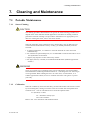
7. Cleaning and Maintenance ....................................................................................... 7-1
7.1
Periodic Maintenance ......................................................................................
7.1.1 Sensor Cleaning .......................................................................................
7.1.2 Calibration ...............................................................................................
7.2 Checks and Preventive Maintenance ..............................................................
viii
7-1
7-1
7-1
7-2
IM 12D11A01-01E
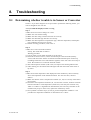
8. Troubleshooting .......................................................................................................... 8-1
8.1
8.2
8.3
Determining whether trouble is in Sensor or Converter ................................
Error display ....................................................................................................
Things to do when an error is detected ..........................................................
8.3.1 Error E-1 Conductivity input is out of measurement range ...................
8.3.2 Error E-2 Temperature measurement is out of range .............................
8.3.3 Error E-3 Temperature sensor abnormal .................................................
8.3.4 Error E-4 Converter abnormal ................................................................
8.3.5 Error E-5 Temperature Compensation Out of Range .............................
8.3.6 Calibration Error C-1 Standard solution temperature out of range ........
8.3.7 Calibration Error C-2 Calibration abnormal ...........................................
8.3.8 Calibration Error C-3 Zero calibration abnormal ...................................
8.3.9 Calibration Error C-4 The used standard liquid conductivity out of
measurement range ..................................................................................
8.4
Things to do when measurement value is abnormal. .....................................
8-1
8-6
8-7
8-7
8-7
8-7
8-8
8-8
8-8
8-8
8-9
8-9
8-9
Revision Record .................................................................................................................... i
IM 12D11A01-01E
ix
x
IM 12D11A01-01E
1. Overview
1.
Overview
1.1
EXA SC100 conductivity converter
The EXA SC100 conductivity converter is a panel-mount unit with built-in generalpurpose preamp, large 4-digit LED display for measured value and 4-digit LED display
for settings.
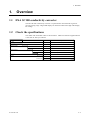
1.2
Check the specifications
The model code and suffix codes are shown below. Make sure that the supplied SC100
is the same as what you ordered.
Model
Suffix code
Option code
SC100
22222
Label language
Always -A
-A
English
-E
Japanese
-J
Contact output
2 contact outputs
-21
4 contact outputs
-41
22222
Option
Description
Panel mount conductivity converter
Always -NN
-NN
Unit
Construction
/UNT
S/m
/65
IP65
T02.EPS
IM 12D11A01-01E
1-1
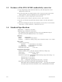
1.3
Features of the EXA SC100 conductivity converter
(1) Large 4-digit display. Both measured conductivity value and temperature can be
displayed at the same time.
(2) You can select either two output contacts or four ; and you can select each contact
output type from : high, low, high high, low low, and high high / low low.
(3) An isolated 4 to 20 mA analog output of measured value.
(4) The operation panel is rated for operation in an IP55. IP65 is optional.
(5) 96 mm x 96 mm DIN size panel-mount analyzer. Depth is 120 mm and weight is
600 g.
(6) Full set of self-diagnostic functions with indication of errors such as "out of measurement range", "converter abnormal", "calibration-time error".
1.4
Standard Specifications
Measurement: Conductivity of solution
Measuring range: 0.05mS/cm to 200 mS/cm
Note: Measuring range is defined by the sensor to be used. Maximum range of
applicable sensors (SC10XB and SC4A) is 0 to 2.0 mS/cm.
Indication
Display:
Range:
Indication:
Digital (LED)
0.000mS/cm to 200.0 mS/cm
Conductivity reading, setting, status, temperature (range: -10 to 1108C)
Input signal
Conductivity input range:
Minimum:
5 mS/cm3K (K: cell constant)
Maximum:
50 mS/cm3K (K: cell constant)
Temperature input:
Pt1000/Pt100
Temperature input range:
-10 to 1108C
Transmission signal output
Number of output points: 1 point (for output of conductivity reading only)
Output signal:
4 to 20 mA DC, isolated
Load resistance:
600 V or less
Transmission signal range: Configurable within measuring range (initial setting : 0 to
200 mS/cm)
Minimum span: 0 to 0.2 mS/cm
Maximum span: 0 to 200 mS/cm
Note: Configurable range depends on the sensor to be used.
Maintenance output signal: Output hold "enabled/disabled" selectable
Hold output value: Last measured value/preset value
(2.0 to 20.8 mA) selectable
Fail output signal: Downscale burndown (2 mA) "enabled/disabled" selectable
1-2
IM 12D11A01-01E
1. Overview
Contact output
Contact type : Relay contact output
Number of contacts : 2 or 4 outputs (must be specified when ordering)
Contact action : On/Off action
Contact functions : Selectable; High, low, high-high, low-low, high-high/low-low limit
alarms, FAIL
Contact output hysteresis : 0 to 100% (configurable)
Contact output delay time : 0 to 200 seconds (configurable)
Contact rating :
When 2 contact outputs specified
S1 : 240 VAC 3A or 30 V DC 3A (resistance load), Form C (NC/NO/COM, 3
terminals)
S2 : 240 VAC 3A or 30 V DC 3A (resistance load), Form A (NO/COM, 2
terminals)
When 4 contact outputs specified
S1 : 240 VAC 3A or 30 V DC 3A (resistance load), Form C (NC/NO/COM, 3
terminals)
S2, S3, S4 : 240 V AC 3A or 30 V DC 3A (resistanceload), Form A, shared common
Maximum load current on common is 3A.
Contact status:
Table 1.1
Terminal
Contact
S1
NO-COM
NC-COM
S2
S3 when specified
S4 when specified
Function selected
H, L, HH, LL, HH/LL limit alarms
Power on
Power off
No alarm Alarm
Open
Open
Closed
Closed
Closed
Open
Open
Open
Closed
Open
Open
Closed
Open
Open
Closed
Note: When a contact is activated, the LED on display panel turns on.
1
Power off
Open
Closed
Open
Open
Open
FAIL
Power on
No alarm Alarm
Closed
Open
Open
Closed
Closed
Open
Closed
Open
Closed
Open
S1
2
COM
3
S2
4
S3
5
S4
6
COM
7
NC
NO
Ambient temperature : -5 to 45 8C
Installation altitude: 2000 m or less above sea level
Storage temperature : -25 to 70 8C
Ambient humidity : 10 to 90% RH, non-condensing
Construction : Front panel : Dust-proof and drip-proof construction IP55,
IP65 (when “/65” option specified)
Materials : ABS resin and polycarbonate
Case color : Black
Rated Power supply : voltage : 100 to 240 V AC (610%), 50/60 Hz
Power consumption : Max. 9 VA
Weight : Approx. 600g
Dimensions : 96 (W) 3 96 (H) 3 120 (D) mm
Mounting : Panel mount
Panel cutout dimensions : 92 (W) 3 92 (H) mm
Wiring : M3.5 screw terminal
Grounding : grounding resistance 100 V or less
IM 12D11A01-01E
1-3
Conformance to Safety and Standards
Conforms to IEC1010-1: 1990 and EN61010-1: 1992.
Certified for CSA1010.
The overvoltage category of each input is CAT II (IEC1010-1)
Certified for UL61010C. *l
*l
"Overvoltage category (Installation category)" describes a number which defines a
transient overvoltage condition. It implies the regulation for inpulse withstand voltage.
" II " applies to electrical equipment which is supplied from the fixed installation like
distribution board.
" I " applies to electrical equipment which is supplied from the circuit when appropriate transient overvoltage control means (interfaces) are provided.
Note: CSA, UL are pending.
Functional specifications
Reference temperature conversion: 0.00 to 10.00%/8C or NaCl coefficient compensation
Reference temperature setting range:
0 to 1008C
Cell constant setting range:
0.0001 to 12.00 cm-1
Temperature value adjustment (cable length correction by temperature 1-point calibration)
Sensor cable length correction
Calibration function
Manual zero calibration (air calibration)
Span calibration (specified setting by specified solution, 1-point calibration)
Note: Temperature indication is available during manual calibration
Self-diagnostics function
FAIL output: Measuring range failure, temperature range failure, temperature sensor
failure, converter failure, invalid temperature compensation
Error indication: Calibration value failure, abnormal temperature range during calibration,
calibration solution measuring range failure
Converter performance: under normal operating conditions
Repeatability: 61% of span
Note: Span refers to the one of input range.
Temperature reproducibility: 618C
Transmission output accuracy: 60.3% of span
Note: Span refers to one of transmission signal output range.
Applicable sensors:
SC10XB Conductivity Sensor for SC100
Cable lenght : 3,5,10m
Extension cable length : up to 50m (Using the WTB100 terminal box)
Note : Extension cable length means that total cable length including sensor
cable is within 50m
Wetted part materials :
In applying piping adapter : SUS316, polypropylene and rigid PVC resin
(SC10XB) rigid PVC resin (adapter), Viton R
fluoroelastomer (O-ring for adapter)
In applying drop-in-type : SUS316, polypropylene, ridid PVC resin, silicone
rubber, PPS regin chlorinated polythylene rubber
(for cable seath)
SC4A 2-electrode Conductivity Sensor
Note: Refer to document GS12D08F03-01E when using SC4A sensor.
1-4
IM 12D11A01-01E
2. Preparation for Operation
2.
2.1
Preparation for Operation
Unpacking
When the instrument arrives, unpack the package with care and check that the instrument has not been damaged during transportation. In addition, please check that the
specification matches the order, and required accessories are not missing.
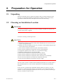
2.2
Choosing an Installation Location
WARNING
To minimize the danger of shock, the converter should be mounted on a panel for the
converter when power is applied.
Cautions in choosing a mounting location
CAUTION
(1) Mount the converter in a location which allows adequate space for access from the
rear for wiring and the like,
(2) Ideally the converter should be on the rear of a panel, so that unauthorized personnel
will not have access to the terminals,
(3) The converter should be located in a place with minimal vibration,
(4) The converter should not be exposed to corrosive gas atmospheres,
(5) Temperature should be near normal (23 8C) with minimal change,
(6) Humidity should be between 10% and 90% RH,
(7) The converter should not be exposed to direct heat radiation,
(8) The converter should not be exposed to strong magnetic fields,
(9) The converter should not be exposed to water or moisture to be condensed,
(10) The converter should not be mounted near flammable materials,
(11) The converter should not be exposed to strong UV light.
The case of the converter is made of flam-retarded polycarbonate resin, and the bezel is
flam-retarded ABS resin, so the converter should not be mounted above flammable
materials.
If the converter is mounted near flammable materials against our caution, cover the
converter by a plated steel plate at least 1.43 mm thick, or an uncoated steel plate of
thickness 1.6 mm, separating the material from the converter top, bottom, left and right
sides by a clearance of least 150 mm.
IM 12D11A01-01E
2-1
150 mm
150 mm
150 mm
150 mm
F2.1.EPS
Fig. 2.1
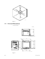
2.3
External Dimensions
• SC100 Converter
1-10
91.6 Max.
51-60 41-50 31-40 21-30 11-20
Unit: mm
Power supply terminal cover
11
111
111
mS/cm
mS/cm
S3
S4
96
S1
S2
91.6
EXASC100
CANCEL
CAL
MEAS
SET
ENT
96
Panel depth: 1 to 10
100
F2.2E.EPS
Fig. 2.2
2-2
IM 12D11A01-01E
2. Preparation for Operation
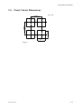
2.4
Panel Cutout Dimensions
Unit : mm
92 +0.8
0
145 Min.
125 Min.
92 +0.8
0
Fig. 2.3
IM 12D11A01-01E
2-3
2.5
Mounting
Large brackct (mount at top)
Panel
Terminal board
Insert from this
Side of panel
Insert driver to
tighten bracket
Small bracket (mount at bottom)
Fig. 2.4
Procedure 1
Cut panel out to mount the SC100 converter, referring to cutout dimensions shown
on previous page.
Procedure 2
Insert the rear of the converter (terminal block side) in panel cutout.
Procedure 3
Mount top and bottom brackets (see figure) to fix the converter to panel.
*When detector output is to be prewired, refer to Sec. 3.4(2)
WARNING
When mounting the converter to the cutout, do not tightly fit them, do not force it
because its case or mounting brackets may be damaged.
2-4
IM 12D11A01-01E
2. Preparation for Operation
WARNING
Up to
308
Install the converter within below 308 from the line perpendicular to the panel board.
Do not face the front of the converter upward.
F2.5.EPS
Fig. 2.5
IM 12D11A01-01E
2-5
2-6
IM 12D11A01-01E
3. Wiring
3.
Wiring
This section explains wiring of the EXA SC100 conductivity converter.
WARNING
Be sure to turn off power supply, and make sure, with a tester or the like, that the
dangerous voltage is not applied to cable to be connected. Do not touch terminals if power
be applied.
The recommended specifications for wiring terminals are shown below.
Use crimp-on terminals, designed to fit an ISO M3.5 screw, with an insulating sleeve.
3.7mm
Up to 7mm
Up to 7mm
3.7mm\
F3.1.EPS
Fig. 3.1
Table 3.1 Recommended terminals
Maker
model
Japan AMP Co., Ltd
JST Co., Ltd
1.25-YS3A
YD1.25-3.5
For wire size:
0.3~1.65mm
Tightening torque
0.8N . m (8 kgf . cm) Up to or Iess
T3.1.EPS
IM 12D11A01-01E
3-1
3.1
Direction of cable terminals fixing
When wiring cables to terminals on the rear of the instrument, put the cable terminals in
the terminal face of the converter in such direction as to draw the cable to left side. (see
Fig. 3.2)
CAUTION
There’s a terminal wiring diagram on the nameplate on the side of the converter.
Put in cable terminals from left side
Terminal name
S1(NC)
Terminal name
C1
1
11
S1(NO)
2
12
COM1
3
13
S
S2
4
14
I1
S3
5
15
I2
T1
C2
S4
6
COM2
7
17
L
8
18
T2
N
9
19
mA (1)
10
20
mA (2)
Power
cable Ground
cable
16
Conductivity Analog output
sensor
cable
cable
Converter rear panel
F3.2.EPS
Fig. 3.2 Direction to put cable terminals
3-2
IM 12D11A01-01E
3. Wiring
3.2
Noise prevention
dNoise sources
The following are typical sources of electrical noise
* Relays and contacts
* Solenoid coil, solenoid valre
* Solenoid coil, solenoid valve
* Power lines
* Inductive loads
* Inverters
* Motor commutators
* SCRs used for phase-angle control
* Wireless transmitters
* Welding equipment
* High-voltage ignition systems
dNoise prevention
When wiring, take the following precautions to minimize the effects of noise:
* Keep input circuit wiring as far as possible from power or ground wiring.
* Shielded wires are effective for minimizing pickup of noise from electrostatic
induction.
If neccessary, connect the shield to the ground terminal.
Avoid double-point grounding, though.
* Twisted wires for input are effective in minimizing pickup of noise from electromagnetic induction.
IM 12D11A01-01E
3-3
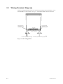
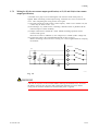
3.3
Wiring Terminal Diagram
There are wiring terminals on the rear of the SC100 converter. Wire to terminals 1 to 10
and terminals 11 to 20 as shown in Fig. 3.3. The terminal block cannot be removed.
Row of terminals
numbered 1 to 10
from top to bottom
Row of terminals
numbered 11 to 20
from top to bottom
Not used
1-10 51-60 41-50 31-40 21-30 11-20
SC100 Top view
F3.3.EPS
Contact output and power wiring
Conductivity sensor and Analog output cable
Fig. 3.3 Cable wiring position
3-4
IM 12D11A01-01E
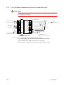
3. Wiring
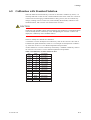
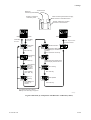
3.3.1
Use of EXA SC100 in combination with the SC10XB dedicated conductivity sensor
CAUTION
Screws on terminals are ISO M3.5. There’s a terminal wiring diagram on the converter
nameplate on the side of the converter.
Terminal
name
Contact output 1 (NC)
Contact output 1 (NO)
Extension cable
WF100-SC *2)
Terminal box
WTB100-SC *1)
1
S1(NC)
Terminal name
C1
11
C1
2
S1(NO)
C2
12
C2
3
COM1
S
13
S
Contact output 2
*3)
Contact output 3
4
S2
14
5
S3
15
*3)Contact output 4
6
S4
7
COM2
L
8
L
N
9
N
SC10XB
dedicated
conductivity sensor
16
T1
17
T1
T2
18
T2
mA(1)
19
mA(2)
20
Analog output
10
Shield
Ground to earth
(grounding resistance 100V or less)
Converter Rear View
Ground to earth
(grounding resistance 100V or less)
Fig. 3.4 Wiring diagram when the WTB100 terminal box is used
*1) The terminal box WTB100 is used when conductivity converter and
conductivity sensor are far apart.
*2) The extension cable WF100 is used when conductivity converter and conductivity
sensor are far apart.
*3) When only two contact outputs are specified, contact outputs 3 and 4 (S3 and S4)
are not used. When four contact outputs are used, S3 and S4 share the same
common lead (COM2).
IM 12D11A01-01E
3-5
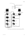
3.3.2
Use of EXA100 in combination with the SC4A conductivity sensor
CAUTION
Screw on terminals are ISO M3.5. There’s a terminal wiring diagram on the nameplate
on the side of the converter.
Terminal
name
Cable conductor number
Contact output 1 (NC)
1
S1(NC)
Terminal name
15
11
15
Contact output 1 (NO)
2
S1(NO)
13
12
13
3
COM1
S
13
Contact output 2
4
S2
14
14
14
Contact output 3
5
S3
16
15
16
Contact output 4
6
S4
COM2
16
T1
17
11
L
8
L
T2
18
12
N
9
N
mA(1)
19
mA(2)
20
7
SC4A
Conductivity sensor
Analog output
10
Ground to earth
(grounding resistance 100V or less)
Shield
Converter Rear View
Ground to earth
(grounding resistance 100V or less)
Note: Terminals are M3.5 screws. Terminal diagram is shown on the name plate on the side of the converter.
Fig. 3.5 Wiring diagram when intermediate terminal box is not used
In this combination, the WTB terminal box is also applicable.
When using the terminal box, refer to the terminal box Instruction manual.
3-6
IM 12D11A01-01E
3. Wiring
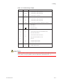
Table 3.2 Terminal wiring example
Terminal no. Signal name
Signal description
1
S1(NC)
Contact output 1 (relay contact) NC
2
S1(NO)
Contact output 1 (relay contact) NO
3
COM1
Contact output 1 (common)
4
S2
Contact output 2 (relay contact)NO
5
S3
Contact output 3 (relay contact) NO
6
S4
Contact output 4 (relay contact) NO
7
COM2
8
L
Power line L
9
N
Power line N
10
Contact output 2 (common) (shared by S2, S3 & S4)
Protective Ground
11
C1
Inner electrode terminal (for SC10XB and SC4A)
12
C2
Outer electrode terminal (for SC10XB and SC4A)
13
S
Electrode shield terminal
14
I1
Outer electrode terminal (for SC4A)
15
I2
Inner electrode terminal (for SC4A)
16
]
Reserved
17
T1
Temperature input terminal
18
T2
Temperature input terminal
19
mA(1)
Analog output terminal (1)
20
mA(2)
Analog output terminal (2)
T3.2.EPS
CAUTION
Figures 3.4 and 3.5 seem to indicate that cable can be pulled in from right hand side, but
in fact cable can only be pulled in from left hand side as described in Sec. 3.1
IM 12D11A01-01E
3-7
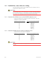
3.4
Conductivity sensor detector wiring
This section describes connection of the SC10XB or the SC4A conductivity sensor to
the EXA SC100 conductivity converter.
CAUTION
For a description of how to connect these sensors via extension cable and terminal box,
refer to the related documents : No. IM 12B11E01-01E for the EXA WTB100 terminal
box, and refer to No. IM 12B11F01-01E for the EXA WF100 extension cable.
3.4.1
Connection of the SC100 converter and the SC10XB conductivity sensor
Connect the conductivity sensor (detector) by cable to the terminals. The correct
combination to coonnect is listed below:
Conductivity converter terminal no.
11
12
13
14
15
16
17
18
3.4.2
Cable core color and code for SC10XB
sensors
White (C1)
Brown (C2)
Green (S)
Do not use
Do not use
Do not use
Red (T1)
Black (T2)
Connection of SC100 converter and SC4A conductivity sensor
Connect the sensor to the terminals as listed below.
Conductivity converter terminal no.
11
12
13
14
15
16
17
18
Cable core color code forSC4A sensor
Black (15)
Green (13)
Do not use
Yellow (14)
Pink (16)
Do not use
White (11)
Black (12)
CAUTION
Since SC4A cable core numbers do not agree with converter terminal numbers, take care
to connect.
3-8
IM 12D11A01-01E
3. Wiring
3.5
Wiring the WF100 Extension Cable
When the EXA SC100 conductivity converter is too far to connect directly the conductivity detector, use the EXA WTB100 terminal box and EXA WF100 extension cable
connect them, following the section 3.4.1.
3.6
Output Signal Cable Wiring
DANGER
To minimize the danger of shock, cut the power supply to the converter before connecting or disconnecting wires of output signal to an instrument such as a recorder.
The output signal wiring from the SC100 converter connects to recorders or the like.
Use two-core shielded cable for this wiring.
(1) Connect output signalcables to the terminals. Connect the cable to the recommended
terminal as show in Fig. 3.1.
Before connecting, remove the core wire covering in a correct length suitable for
crimping the terminal.
(2) As shown in Figures 3.4 and 3.5 of Section 3.3, ground to earth and ground connection at one point only.
3.7
Contact output wiring.
3.7.1
Wiring when S1 is used
A terminal cover plays a role in reducing the risk of electric shock when power is
applied. When connecting contact output wiring, loosen the two screws to remove the
cover. After completing the wiring, fix the cover again.
Terminal no.
NC
1
NO
2
Load
Load
COM
3
F3.6.EPS
Fig. 3.6 Relay contact output wiring
* If a load exceeds the contact rating (switch capacity : 240VAC 3A, 30VDC 3A), a
slave relay needs using.
* Output contacts have a limited life.
No use of such an inductive load as a slave relay or a solenoid valve can cause
malfunction or fault of the contacts.
Don't fail to connect a CR filter (in use of AC voltage ) or a diode (in use of DC
voltege) in parallel with the contacts.
IM 12D11A01-01E
3-9
WARNING
* Be sure to cut power to the converter before removing the terminal cover. To avoid
the danger of shock, turn off power and confirm that terminals are not live before
wiring. Never touch the terminals when power is applied.
Table 3.3 Recommended CR filters
Maker
Models
MATSUO Electric co.,Ltd
CR UNIT 953, 955 etc.
SHIZUKI Electric co.,Ltd
SKV, SKVB etc.
RUBYCON Corporation
CR-CFS, CR-U etc.
T3.3.EPS
• For an DC relay
External DC source
Instrument
R
Diode (mount directly on
relay coil terminals or socket)
Relay (coil rating
must not exceed converter contact rating)
F3.7.EPS
Fig. 3.7
• For an AC relay
External AC source
Instrument
R
CR filter (mount directly on
relay coil terminals or socket)
Relay (coil rating
must not exceed con
veter contact rating)
F3.8.EPS
Fig. 3.8
3-10
IM 12D11A01-01E
3. Wiring
3.7.2
Wiring for S2 (for two-contact-output specification) or S2, S3 and S4 (for four-contact
output specification)
A terminal cover plays a role in reducing the risk of electric shock when power is
applied. When connecting contact output wiring, loosen the two screws to remove the
cover. After completing the wiring, fix the cover again.
(1) If a load exceeds the contact rating (switch capacity : 240VA 3A or 30VDC 3A) use
a slave relay as shown in Sec. 3.7.1.
(2) If switching a very small current, connecting a bleeder resistor in parallel with the
load can improve contact reliability.
(3) Output contact have a limited life : about 100.000 switching operations with a
resistive load, typical.
Don't fail to connect a CR filter (in AC voltage use) or a diode (in DC voltage use).
(4) Connect the cable to the recommended terminal as show in Fig.3.1.
Before connecting, remove the wire covering in a correct length suitable for crimping
the terminal.
Terminal no.
S2
4
S3
5
Load
S4
6
Load
Load
7
COM
F3.9.EPS
Fig. 3.9
WARNING
* Be sure to cut power to the converter before removing the terminal cover. To avoid
the danger of shock, turn off power and confirm that terminals are not live before
wiring. Never touch the terminals be touched when power is applied.
IM 12D11A01-01E
3-11
3.8
Power and Ground Wiring
* Power: This wiring should connect a power source of the correct voltage and frequency to the EXA SC100 Conductivity Converter. The power wiring should be
heavy vinyl sheath cable rated at 600V insulation resistance (specifications equivalent
to JIS C 3307).
* Ground: Ground to earth (ground resistance 100 ohms or less). Use a sufficiently
heavy cable (cross sectional area of 2 mm2 or greater, nominal).
* Use the recommended terminals to terminate connecting cables, and make sure that
they are the correct size to match the cable core diameter.
A terminal cover is fitted to reduce the risk of electric shock when power is applied.
When connecting contact output wiring, you need to loosen the two cover screws to
remove the cover. After completing the wiring, take care not to forget to replace the
cover.
WARNING
* Be sure to cut power to the converter before removing the terminal cover. To avoid
the danger of shock, turn off power and confirm that terminals are not live before
wiring. Never touch the terminals be touched when power is applied.
CAUTION
The EXA SC100 conductivity converter does not have a power switch built in. You
should add an on-off switch with two poles (to disconnect both sides of the power line).
EXA SC100 conductivity
converter 1 ~ 10 Terminal no.
Switch (provided by user)
1
S1(NC)
2
S1(NO)
3
COM1
4
S2
5
S3
6
S4
7
COM2
8
L
9
N
Power wiring
Power
10
F3.10.EPS
Fig. 3.10
3-12
IM 12D11A01-01E
4. Overview of Operation Panel
4.
4.1
Overview of Operation Panel
Overviews of names and functions of operation panel
keys
1
Measured value display
4-digit display
*When measuring: conductivity value is
displayed
*When measuring or calibrating: numerical
data and alphanumerics is displayed
2
Auxiliary display
4-digit display
When measuring: measured temperature
is displayed (selectable)
When setting: parameters
4
Keypad area
Three keys:
*SET/ENT key
* m key
* . key
SET/ENT key
. key
3
m key
Status display
Four LEDs (When 2 contact outputs specified : two LEDs)
*Display contact output status (lit when operated)
F4.1E.EPS
Fig. 4.1
IM 12B11A01-01E
4-1
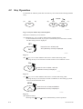
4.2
Key Operation
On the EXA SC100 front panel there are three keys for screen/mode switching and data
entry.
CANCEL
(A)
SET
(B)
key
CAL
(C)
MEAS
ENT
F4.2E.EPS
Fig. 4.2 Layout of three keys on front panel
Main uses of these keys are as follows:
(A) SET/ENT key: Use to confirm mode changes and data settings
* At the measurement mode, if you press it continuously for at least three seconds,
the data setting screen is displayed.
SET
Press for 3 sec. at least, and
ENT
SET (data entry screen) is displayed.
F4.3E.EPS
Fig. 4.3
(B) ( ) key: Use to select different menu item or reduce data setting value.
* Pressing this key for at least three seconds switches to the calibration screen.
CAL
Press for 3 sec. at least , and CAL
(calibration screen) is displayed.
F4.4E.EPS
Fig. 4.4
(C) ( ) key: Use to select different menu item or increase data setting value.
* Pressing this key for at least three seconds in calibration or data setting top mode
return to the measurement mode.
MEAS
Press for 3 sec. at least, and MEAS
(measurement screen) is displayed.
F4.5E.EPS
Fig. 4.5
(D) Operation cancel
* Pressing both ( ) and (
4-2
)) screen simultaneously cancels operations
IM 12D11A01-01E
4. Overview of Operation Panel
4.3
Switching mode to Displated
EXA PH100 has three menu screens: measurement, calibration and data setting screens.
The screen transition diagram is shown below.
Power ON
Initial mode (4?4?1)
Measurement mode
Press (
) key for 3 seconds
Calibration mode
(4?4?2)
Press SET/ENT key
for three seconds
Press (
Press (
) key for 3 seconds
(4?4?3)
) key for 3 sec.
Data setting mode
(4?4?4)
F4.6E.EPS
Fig. 4.6
IM 12B11A01-01E
4-3
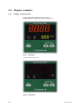
4.4
Display examples
4.4.1
Display in Initial model
Display when the SC100 converter is normal.
(1) All LEDs are lit when the converter is powered on.
F4.7E.EPS
Fig.4.7. All LEDs lit
(2) Then all LEDs turn off.
F4.8E.EPS
Fig.4.8. All LEDs off
4-4
IM 12D11A01-01E
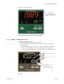
4. Overview of Operation Panel
(3) Move to measurement mode
Note:
" ] ] ] ]" is displayed on
measured value display portion
in case of unstable measured
value.
F4.9E.EPS
Fig. 4.9 Measurement mode with temperature display
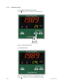
4.4.2
Display in Measurement mode
1) Display in Measurement mode
* Measurement display: Displays conductivity value.
The position of Decimal point automatically moves among four-digit numbers.
* Auxiliary display:
When temperature display functions are enable, the temperature and units (C
for 8C, F for 8F) are displayed. When temperature display functions are
unenable, nothing is displayed. (The initial setting is for no temperature display).
Conductivity display - up to 4 digits
Conductivity units mS/cm or mS/cm
When temperature display is enable.
temprature is displayed.
*1 When Sufflx Code / UNT specified,
mS/cm, mS/cm, S/m are provided
F4.10E.EPS
Fig. 4.10
IM 12B11A01-01E
4-5
4.4.3
Calibration mode
(1) Switching From Measurement mode
Press ( ) key for 3 sec. to transfer to Calibration mode
F4.11E.EPS
Press for at less3 sec.
Fig. 4.11 Measurement mode
(2) Calibration mode
F4.12E.EPS
Fig. 4.12 Calibration mode (for Autocalibration mode)
Press ( ) for at less 3 sec. to return to Measurement mode
4-6
IM 12D11A01-01E
4. Overview of Operation Panel
4.4.4
Setting mode
(1) Measurement mode display
Press SET/ENT key for at least 3 sec. to transfer to Setting mode.
F4.13E.EPS
Press for at less3 sec.
Fig. 4.13 Measurement mode
(2) Setting screen
F4.14E.EPS
Fig. 4.14 Setting mode
Press ( ) for at less 3 sec. to return to Measurement mode
IM 12B11A01-01E
4-7
4-8
IM 12D11A01-01E
5. Operation
5.
Operation
5.1
Start up
5.1.1
Check wiring
Check that all wiring is correct (refer to Sec. 3.3)
5.1.2
Start up Conductivity Converter
Apply power (100 to 240V AC 6 10% 50/60Hz) to EXA SC100 conductivity converter.
5.1.3
Data Setting
Set the following parameters after switching the Data setting mode -- (1) analog output
parameter, (2) calibration parameters, (3) alarm settings, and (4) other parameters -- in
the order listed, to enable desired operation for process conductivity control:
(1) Analog output parameters
“Ao.PA”, at the analogue output parameters setting mode, is displayed on the
Measured Value display area.
This mode is for user setting of analogue-output-related settings
(2) Alarm parameters (Page 5-4, 5-5)
“Alrm”, at the calibration parameters setting mode, is displayed on the Measured
Value display area.
This screen is for user setting of alarm-related settings
(3) Other parameters
“otHr”, at the calibration parameters setting mode, is displayed on the Measured
Value display area.
This mode is for user setting of parameter settings other than (1) to (2) above.
Note
See Sec. 4 “Overview of Operation Manual” and table of LED display symbols in
preface to this manual.
IM 12D11A01-01E
5-1
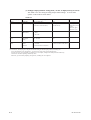
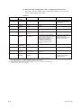
(1) Analogue output parameter setting mode (“Ao.PA” is displayed at top of screen)
This mode is for user setting of analog-output-related settings. A list of menu
options on this mode is shown below:
Table 5.1
Letters displayed
Parameter
Setting range
Initial value
Ao.PA
Menu Title
NA (not applicable)
NA
rH
Upper limit Range
0.2 mS/cm to 200.0 mS/cm (*1)
(0.02 mS/cm to 20.00 mS/m)
200.0 mS/cm
(20.00 mS/cm)
M.HLd
Hold during
Maintenance
0 : No Hold
1 : Hold
2 : Set value
1 : Hold
H.Ao
Hold output
setting
2.0 ~ 20.8mA
2.0
F.HLd
Hold if
abnormal
0 : No Hold
1 : Burn out down scale (2mA)
1 : Burn out down scale (2mA)
*1: It is possible to input 0.19 mS/cm or less with key, but this value is not set and does not become valid.
*2: For instance, when trying to set 20 mS/cm without moving the decimal point position, the setting can
be not "20.00 mS/cm" but "20.0 mS/cm".; you cannot set a value to the second decimal place.
For this reason, in case of inputting "19.99 mS/cm" as an example, setting the decimal point and conductivity
unit must be set before inputting conductivity value.
Otherwise, you cannot help inputting "20.0 mS/cm", rounding off "19.99 mS/cm".
5-2
Note
Decimal point and
conductivity unit is
set first.
After this, upper
limit is set. (*2)
T5.1E.EPS
IM 12D11A01-01E
5. Operation
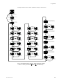
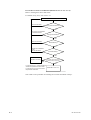
Example flow chart for analog output parameter setting is shown below
EXA
S1
S3
S2
S4
SC100
mS/cm
mS/cm
CANCEL
SET
CAL
MEAS
ENT
mesurement screen model
Press m key 3 sec.
Press SET/ENT key for 3 sec.
EXA
S1
S3
S2
S4
SC100
mS/cm
mS/cm
Ao. PA blinking
Analog output parameter seting screen mode
SET/ENT key
EXA
S1
S3
S2
S4
SC100
mS/cm
mS/cm
Change the decimal point position
with m or . key.
Conductivity unit is changed
by changing the decimalpoint position
SET/ENT key
EXA
S1
S3
S2
S4
Upper
limit range
Usem and . keys to
change value
SC100
mS/cm
mS/cm
EXA
S1
S3
S2
S4
SC100
EXA
mS/cm
mS/cm
SET/ENT key
SET/ENT key
(rewrites data)
EXA
S1
S3
S2
S4
Fold during
maintenance
Usem and . keys to
change value
SC100
mS/cm
mS/cm
EXA
S1
S3
S2
S4
S1
S3
S2
S4
Hold output
setting
EXA
S1
S3
S2
S4
Hold if
ubnormal
SET/ENT key
SET/ENT key
(rewrites data)
mS/cm
mS/cm
EXA
S1
S3
S2
S4
SC100
mS/cm
mS/cm
SET/ENT key
SET/ENT key
(rewrites data)
SC100
mS/cm
mS/cm
Usem and . keys to
change value
SC100
Usem and . keys to
change value
SC100
mS/cm
mS/cm
EXA
S1
S3
S2
S4
SC100
mS/cm
mS/cm
SET/ENT key
SET/ENT key
(rewrites data)
F5.1E.EPS
Fig. 5.1 Example flow chart for analog output parameter setting
* Note: To cancel, press both ( ) and ( ) simultaneously.
IM 12D11A01-01E
5-3
(2) Alarm parameter setting mode (“Alrm” is displayed at top of screen)
This mode is for user setting of alarm data. A list of menu options on this mode is
shown below:
Table 5.2
Parameter
Letters displayed
Alrm
top menu
Setting range
NA (not applicable)
Initial value
S1
S1
HY1
S1 hysteresis
0: high limit alarm
1: low limit alarm
2: high high limit alarm
4: high high limit/low low limited alarm
5: abnormal
0-100 %
dL1
S1 delay time
0-200 seconds
0
S2
S2
0: high limit alarm
1: low limit alarm
2: high high limit alarm
4: high high limit/low low limited alarm
5: abnormal
1: low limit alarm
HY2
S2 hysteresis
0-100 %
2%
dL2
S2 delay time
S3
S3
0-200 seconds
0: high limit alarm
1: low limit alarm
2: high high limit alarm
4: high high limit/low low limited alarm
5: abnormal
HY3
S3 hysteresis
dL3
Note
NA
0: high limit alarm
2%
0
2: high high limit alarm
when suffix
code is -21,
S3 does not
appear
0-100 %
2%
when suffix
code is -21,
HY3 does not
appear
S3 delay time
0-200 seconds
0
when suffix
code is -21,
dLY3 does not
appear
S4
S4
0: high limit alarm
1: low limit alarm
2: high high limit alarm
3: low low limit alarm
4: high high limit/low low limited alarm
5: abnormal
3: low low limit alarm
when suffix
code is -21,
S4 does not
appear
HY4
S4 hysteresis
0-100 %
2%
when suffix
code is -21,
HY4 does not
appear
dL4
S4 delay time
0-200 seconds
0
when suffix
code is -21,
dLY4 does not
appear
H.A
high limit alarm
0.000 mS/cm - 200.0 mS/cm
(0.0 mS/m - 20.00 S/m)
200.0 mS/cm
(20.00 mS/m)
L.A
low limit alarm
0.000 mS/cm - 200.0 mS/cm
(0.0 mS/m - 20.00 S/m)
0.000 mS/cm
(0.0 mS/m)
HH.A
high high limit alarm
0.000 mS/cm - 200.0 mS/cm
(0.0 mS/m - 20.00 S/m)
200.0 mS/cm
(20.00 mS/m)
LL.A
low low limit alarm
0.000 mS/cm - 200.0 mS/cm
(0.0 mS/m - 20.00 S/m)
0.000 mS/cm
(0.0 mS/m)
T5.3.EPS
5-4
IM 12D11A01-01E
5. Operation
Example of flow chart for alarm parameter setting is shown below
EXA
S1
S3
S2
S4
SC100
mS/cm
mS/cm
CANCEL
SET
CAL
MEAS
ENT
Measurement screen mode
Press SET/ENT key
for 3 sec.
Press m key
for 3 sec.
EXA
SC100
Ao.PA blinking
Press m key
for 3 sec.
S1
S3
S2
S4
mS/cm
mS/cm
Press m key
Press . key
EXA
EXA
SC100
S1
S3
S2
S4
SC100
mS/cm
mS/cm
Cange decimal point position and
conductiviting unit with m or . key
ALrm blinking
Alarm parameter
S1
S3
S2
S4
SET/ENT key
mS/cm
mS/cm
SET/ENT key
EXA
S1
S3
S2
S4
EXA
Usem and . keys to
change value
SC100
mS/cm
mS/cm
EXA
S1
S3
S2
S4
EXA
SC100
mS/cm
mS/cm
S1
EXA
S1
S3
S2
S4
S1
hysteresis
mS/cm
mS/cm
EXA
S1
S3
S2
S4
S1
S3
S2
S4
EXA
SC100
mS/cm
mS/cm
S1
S3
S2
S4
High limit
EXA
mS/cm
mS/cm
S1
S3
S2
S4
S3
hysteresis
Usem and . keys to
change value
SC100
mS/cm
mS/cm
EXA
S1
S3
S2
S4
Usem and . keys to
change value
SC100
S4
SET/ENT key
SET/ENT key
SC100
S1
S3
S2
S4
SC100
mS/cm
mS/cm
Cange decimal point position and
conductiviting unit with m or . key
SET/ENT key
mS/cm
mS/cm
EXA
SC100
EXA
S1
S3
S2
S4
Usem and . keys to
change value
SC100
mS/cm
mS/cm
EXA
S1
S3
S2
S4
Low limit
S1
S3
S2
S4
S1
delay time
EXA
mS/cm
mS/cm
S1
S3
S2
S4
SET/ENT key
SET/ENT key
S1
S3
S2
S4
mS/cm
mS/cm
S1
S3
S2
S4
S3delay time
EXA
mS/cm
mS/cm
SET/ENT key
(rewrites data)
(rewrites data)
EXA
SC100
EXA
Usem and . keys to
change value
SC100
mS/cm
mS/cm
SET/ENT key
SET/ENT key
alarm
SC100
SET/ENT key
(rewrites data)
Usem and . keys to
change value
SC100
mS/cm
mS/cm
mS/cm
mS/cm
(rewrites data)
EXA
(rewrites data)
EXA
S3
S2
SC100
SET/ENT key
SET/ENT key
SC100
S1
alarm
(rewrites data)
SC100
EXA
mS/cm
mS/cm
SET/ENT key
(rewrites data)
Usem and . keys to
change value
SC100
mS/cm
mS/cm
SET/ENT key
SET/ENT key
SET/ENT key
EXA
S4
EXA
(rewrites data)
Usem and . keys to
change value
SC100
S3
S2
SC100
S3
SET/ENT key
SET/ENT key
S1
Usem and . keys to
change value
Usem and . keys to
change value
SC100
EXA
SC100
S1
S3
S2
S4
SC100
mS/cm
mS/cm
Cange decimal point position and
conductiviting unit with m or . key
pH
S1
S3
S2
S4
mS/cm
mS/cm
S1
S3
S2
S4
mS/cm
mS/cm
S2
SET/ENT key
SET/ENT key
S1
S3
S2
S4
S4
mS/cm
mS/cm
S1
S3
S2
S4
EXA
SC100
EXA
SC100
EXA
(rewrites data)
Usem and . keys to
change value
SC100
SET/ENT key
SET/ENT key
SET/ENT key
(rewrites data)
Usem and . keys to
change value
mS/cm
mS/cm
EXA
SC100
EXA
S1
S3
S2
S4
SC100
EXA
mS/cm
mS/cm
S1
S3
S2
S4
High-high
S1
S3
S2
S4
mS/cm
mS/cm
S2
hysteresis
S1
S3
S2
S4
SET/ENT key
SET/ENT key
EXA
S1
S3
S2
S4
S2
delay time
(rewrites data)
Usem and . keys to
change value
SC100
mS/cm
mS/cm
SET/ENT key
mS/cm
mS/cm
EXA
S1
S3
S2
S4
S1
S3
S2
S4
S4
hysteresis
SC100
SET/ENT key
(rewrites data)
S1
S3
S2
S4
S4
delay time
S1
S3
S2
S4
mS/cm
mS/cm
SET/ENT key
limit alarm
(rewrites data)
Usem and . keys to
change value
SC100
mS/cm
mS/cm
mS/cm
mS/cm
SET/ENT key
SET/ENT key
(rewrites data)
SET/ENT key
SET/ENT key
EXA
mS/cm
mS/cm
mS/cm
mS/cm
SC100
EXA
S1
S3
S2
S4
SC100
EXA
S1
S3
S2
S4
SC100
mS/cm
mS/cm
Cange decimal point position and
conductiviting unit with m or . key
mS/cm
mS/cm
SET/ENT key
(rewrites data)
EXA
S1
S3
S2
S4
Usem and . keys to
change value
SC100
mS/cm
mS/cm
Low-low
limit alarm
EXA
S1
S3
S2
S4
SC100
mS/cm
mS/cm
SET/ENT key
SET/ENT key
(rewrites data)
F5.2E.EPS
Fig. 5.2 Example of flow chart for alarm parameter setting
* Note: To cancel, press both ( ) and ( ) simultaneously.
IM 12D11A01-01E
5-5
(3) Other parameter setting mode ("other" is displayed at top of screen)
This mode is for user setting of other measurement parameter. A list of menu
options on this mode is shown below:
Table 5.3
Letters displayed
Parameters
Setting range
]
Initial Value
]
otHr
Menu title
C.C
Cell constant
0.0001,12.00 cm-1 (*1)
1.00
Cb.r
Wiring resistance
0.00,50.00V
0.00V
dP.t
Temperature
0: OFF
0: OFF
display
1: ON
Unt
Temperature Unit
0: 8C
Note
Set the decimal point and
conductiving unit first. After this,
set the numbers.
0: 8C
1: 8F
t.Sn
RTD type
0: Pt1000
0: Pt1000
1: Pt100
t.CL
S.tC
St.t
Temperature
-15.0,115.0 8C (*2)
Calibration
(5.0,239.0 8F)
Temperature
0: Temperature Cofficient
Compensation
1: NaCl
Standard
0,1008C (14,230 8F)
For your reference, intial temperature
is displayed as what has been measured
right after switchig temererature
calibration mode. In addition, Once
the templerature is displayed,
the temperature keops constant
even though measurement value
changes.
with m or . key, actual temperature
of measurement sample.
Temperature measurement error is
corrected by this operation.
0: Temperature Cofficient
258C (77 8F)
temperature
t.Co
d.InS
temperature
0.0,10.00 %/8C
0.008
coefficient
(0.0,18.00 %/8F)
(0.00 %/8F)
InsP menu display 0: no display
flag setting
0: no diaplay
1: display
Always set "0".
when the power is turned off,
the setting become "0".
(*1) When no decimal point is displayed, setting range is 0.0001-0.0999 cm-1 (display 0001-0999)
When 3 digits below dec. pt., setting and display ranges are 0.001-0.999 cm-1
When 2 digits below dec. pt., setting and display ranges are 0.01-12.00 cm-1
(*2) Actual liquid temperature entered may be in the range —20.0 to +5.0…C relative to displayed value.
If RTD is changed, display may change to [ - - - - ]
5-6
T5.3.EPS
IM 12D11A01-01E
5. Operation
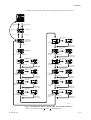
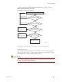
Example of flow chart for setting other measurent parameters is shown below
EXA
S1
S3
S2
S4
SC100
mS/cm
mS/cm
CANCEL
SET
CAL
MEAS
ENT
Mesurement screen mode
Press m key for
3 sec.
Press SET/ENT key for
3 sec.
EXA
Press m key for
3 sec.
Ao.PA blinking
S1
S3
S2
S4
mS/cm
mS/cm
Push . key 2 times
Push m key 2 times
EXA
S1
S3
S2
S4
EXA
SC100
mS/cm
mS/cm
otHr blinking
other parameter
seting mode
S1
S3
S2
S4
Usem and . keys to
change value
SC100
mS/cm
mS/cm
EXA
S1
S3
S2
S4
SC100
mS/cm
mS/cm
Set RTD type
SET/ENT key
SET/ENT key
(rewrites data)
EXA
S1
S3
S2
S4
Cell constant
SC100
EXA
mS/cm
mS/cm
Usem and . keys to
change value
S1
S3
S2
S4
Temperature
calibration
SET/ENT key
Usem and . keys to
change value
SC100
mS/cm
mS/cm
EXA
S1
S3
S2
S4
SC100
mS/cm
mS/cm
SET/ENT key
SET/ENT key
(rewrites data)
EXA
S1
S3
S2
S4
Usem and . keys to
change value
SC100
mS/cm
mS/cm
EXA
S1
S3
S2
S4
EXA
SC100
mS/cm
mS/cm
S1
S3
S2
S4
Temperature
compensation
SET/ENT key
Usem and . keys to
change value
SC100
mS/cm
mS/cm
EXA
S1
S3
S2
S4
S1
S3
S2
S4
Set wiring
resistance
Usem and . keys to
change value
SC100
mS/cm
mS/cm
EXA
S1
S3
S2
S4
SET/ENT key
(rewrites data)
EXA
SC100
mS/cm
mS/cm
S1
S3
S2
S4
Standard
temperature
SET/ENT key
Usem and . keys to
change value
SC100
mS/cm
mS/cm
EXA
S1
S3
S2
S4
S1
S3
S2
S4
Set temperature
display
Usem and . keys to
change value
SC100
mS/cm
mS/cm
EXA
S1
S3
S2
S4
EXA
S1
S3
S2
S4
Set temperature
coefficient
SET/ENT key
Usem and . keys to
change value
SC100
mS/cm
mS/cm
EXA
S1
S3
S2
S4
Usem and . keys to
change value
SC100
EXA
SC100
mS/cm
mS/cm
SET/ENT key
SET/ENT key
(rewrites data)
SET/ENT key
(rewrites data)
EXA
mS/cm
mS/cm
SET/ENT key
(rewrites data)
SC100
mS/cm
mS/cm
SC100
SET/ENT key
SET/ENT key
(rewrites data)
EXA
mS/cm
mS/cm
SET/ENT key
SET/ENT key
(rewrites data)
EXA
SC100
SC100
EXA
Usem and . keys to
change value
SC100
EXA
SC100
pH
S1
S3
S2
S4
mS/cm
mS/cm
S1
S3
S2
S4
mS/cm
mS/cm
Set temperature unit
SET/ENT key
SET/ENT key
(rewrites data)
S1
S3
S2
S4
Set InSP menu
display and flag
setting
mS/cm
mS/cm
S1
S3
S2
S4
mS/cm
mS/cm
SET/ENT key
SET/ENT key
(rewrites data)
F5.3E.EPS
Fig. 5.3 Example flow chart for setting other measurement parameters
Note: To cancel, press both ( ) and ( ) simultaneously.
IM 12D11A01-01E
5-7
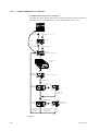
5.1.4
Preparation for Operation
When using the EXA SC100 conductivity converter together with a conductivity
detector, perform initial setup and calibration as follows:
(1) Carefully set correct cell constant as described in Sec. 6.1
(2) Perform wiring compensation
As described in Sec. 6.2, set wiring resistance and perform temperature calibration.
(3) Zero calibration (in air)
As described in Sec. 6.3, perform zero calibration (in air).
(4) Calibration with standard solution
Normally, in start-up, it is not necessary to calibrate with standard solution
5.2
Test Operation
Monitor the EXA SC100 conductivity converter in test- operation mode for a while, in
order to confirm it normally works.
5.3
Normal Operation
From the parameter setting screen mode, press the (
return to the measurement screen.
) key for at least 3 seconds to
Apart from when changing settings or calibrating with standard solution, this converter
doesn’t need operating during normal operation. If an error message is displayed or the
output scales out, referring to Sec. 8 for troubleshooting, find clearly the cause and solve
problems immediately.
In addition, be sure to perform the daily checks and maintenance described in Sec. 7 in
order to maintain reliable operation.
5.4
Stopping and Restarting Operation
Turn simply off the power supply to stop operation.
However, in case of changing settings, be sure to wait at least 2 seconds from this
changing before turning off the power. In other cases, no special precautions are
required.
To restart operation, simply restore power. The parameter values remain the same as
before the power failed.
5-8
IM 12D11A01-01E
6. Settings
6.
6.1
Settings
Setting Cell Constants
The EXA SC100 conductivity converter is used with the dedicated SC10XB conductivity sensor or with the SC4A conductivity sensor; before use it is necessary to enter the
cell constant marked on the cell or the cable. Even for the same type of conductivity
sensor the cell constant varies from cell to cell. You need to enter the cell constant into
the converter before using it.
6.1.1
How to set cell constant
Set cell constant as follows:
EXA
S1
S3
S2
S4
SC100
mS/cm
mS/cm
CANCEL
SET
CAL
MEAS
ENT
Measuring screen
Press m key 3 sec.
Press SET / ENT key 3 sec.
EXA
Press m key 3 sec.
Ao.PA blinks
S1
S3
S2
S4
mS/cm
mS/cm
Press m key 2 times
Press . key 2 times
EXA
SC100
OtHr blinks
Other parameter setting screen
S1
S3
S2
S4
mS/cm
mS/cm
SET / ENT key
EXA
SC100
Use m and . keys to set
dec. pt. position
S1
S3
S2
S4
EXA
mS/cm
mS/cm
Usem and . keys to
change value
SC100
EXA
SC100
Cell constant
setting
S1
S3
S2
S4
Press SET / ENT key
several times to revert
to otHr panel
mS/cm
mS/cm
S1
S3
S2
S4
mS/cm
mS/cm
To skip to next menu without
changing cell constant,
press SET / ENT key
SET / ENT key
( rewrites data )
F6.1E.EPS
Fig. 6.1
IM 12D11A01-01E
6-1
6.1.2
Cell Constant
The default cell constant value is preset to 1.00 cm-1 in the converter at shipping-time.
Before use, change to the cell constant value of the conductivity sensor to be used, as
described in Sec. 6.1.1.
6.1.3
Cell Constant Retention
The cell constant stored in the conductivity converter is retained even when power is
turned off. If the associated conductivity sensor is changed or replaced, then the cell
constant in the converter must be updated accordingly.
6.2
Temperature Compensation Setting
The conductivity is affected by solution temperature - usually the effect of temperature
on conductivity is 2% per 8C temperature change. However the effect depends on
solution composition, concentration, and measurement temperature span, so compensation is determined based on these factors. The coefficient a represents the % change in
conductivity for a 18C temperature change.
Most of applications need to monitor or measure concentration change of solution
without the influence of the temperatur change. For this reason, temperature compensation is meaningful. Table 6.1 shows temperature compensation coefficients for NaCl
solution.
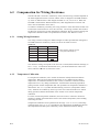
Table 6.1 Compensation for NaCl solution, standard temperature 258C, IEC746-3
T
Kt
a
T
Kt
a
0
0.54
1.8
60
1.76
2.2
10
0.72
1.9
70
1.99
2.2
20
0.90
2.0
80
2.22
2.2
25
1.00
90
2.45
2.2
30
1.10
2.0
100
2.68
2.2
40
1.31
2.0
110
2.90
2.2
50
1.53
2.1
T6.1E.EPS
Kt: Conductivity as a ratio to value at 258C.
T: Liquid temperature (8C).
CAUTION
If the output and display of the conductivity value without compensation is desired, set
the coeffecient “0.00”.
6-2
IM 12D11A01-01E
6. Settings
6.2.1
Determining Temperature Coefficient
If the temperature coefficient of the solution to be measured is not known;
(1) Start by setting the coefficient to zero
(2) Measure the variation in conductivity over a range of 10 to 30 8C (for a standard
temperature of 258C)
(3) Derive a linear approximation for the temperature coefficient using the following
equation:
Temperature coefficient a:
a=
K2 2 K1
K1 (t2 2 25) 2 K2 (t1 2 25)
3 100 (% / 8C)
where t1 , t2 : liquid temperature ( 8C)
K1 : conductivity at temperature t1
K2 : conductivity at temperature t2
25 : Standard temperature ( 8C )
F6.2.1-1E.eps
Calculation example:
Derive a linear approximation for the temperature coefficient for a solution that had a
conductivity of 124.5 m S/cm at 18.0 8C, and a conductivity of 147.6 m S/cm at 31.0 8C
(Standard temperature is 25 8C). Substituting t1 = 18.0, t2 = 31.0, K1 = 124.5, and K2
= 147.6:
a=
=
147.62124.5
124.5 3 (31.0225) 2 147.6 3 (18.0225)
23.1
747.02 (21033.2)
3100
3100
F6.2.1-2E.eps
a = 1.298
For the EXA SC100 conductivity converter, the temperature coefficient can be entered
with just three-digit precision, so we set 1.30
IM 12D11A01-01E
6-3
6.2.2
Setting Temperature Coefficient
(1) Setting Solution Temperature Coefficient
After determining the solution temperature coefficient (whether determined using the
procedure in 6.2.1, or already known), follow the procedure below to set it.
EXA
SC100
mS/cm
S1
S3
S2
S4
mS/cm
CANCEL
SET
CAL
MEAS
ENT
Measuring screen mode
Pressmkey for 3 sec.
Press SET / ENT key for 3 sec.
EXA
Ao.PA blinks
Press m key for 3 sec.
S1
S3
S2
S4
mS/cm
mS/cm
Press m key for 2 sec.
Press.key for 2 sec.
EXA
S1
S3
S2
S4
EXA
SC100
mS/cm
mS/cm
OtHr blinks
(Other parameter setting screen)
SC100
EXA
SC100
EXA
SC100
EXA
SC100
EXA
EXA
Press SET / ENT
key 8 times
SC100
EXA
S1
S3
S2
S4
SC100
mS/cm
mS/cm
SC100
Temperature
compen-sation
setting screen
Confirm that zero is displayed
S1
S3
S2
S4
mS/cm
mS/cm
Press SET / ENT key
EXA
S1
S3
S2
S4
Change value
using m and . keys
SC100
Standard
temperature
setting screen
EXA
mS/cm
mS/cm
S1
S3
S2
S4
SC100
mS/cm
mS/cm
Press SET / ENT
key (writes data)
EXA
Temperature
coefficient
S1
S3
S2
S4
Press SET / ENT key
several times to revert
to otHr panel
Change value
using m and . keys
SC100
mS/cm
mS/cm
EXA
S1
S3
S2
S4
SC100
mS/cm
mS/cm
When temperature
coefficient is 1.30
To skip to next menu without
changing cell constant,
press SET / ENT key
F6.2E.eps
Fig. 6.2
6-4
IM 12D11A01-01E
6. Settings
(2) Setting temperature coefficient for NaCl solution
Procedure for setting NaCl temperature compensation is as follows:
EXA
SC100
mS/cm
S1
S3
S2
S4
mS/cm
CANCEL
SET
CAL
MEAS
ENT
Measuring screen mode
Pressmkey for 3 sec.
Press SET / ENT key for 3 sec.
EXA
Ao.PA blinks
Press m key for 3 sec.
S1
S3
S2
S4
mS/cm
mS/cm
Press m key for 2 sec.
Press.key for 2 sec.
SC100
EXA
S1
S3
S2
S4
EXA
mS/cm
mS/cm
OtHr blinks
(Other parameter setting screen)
SC100
EXA
SC100
EXA
SC100
EXA
SC100
EXA
EXA
Press SET / ENT
key 8 times
SC100
EXA
S1
S3
S2
S4
SC100
mS/cm
mS/cm
SC100
Temperature
compen-sation
setting screen
Confirm that zero is displayed
S1
S3
S2
S4
mS/cm
mS/cm
Press SET / ENT key
EXA
S1
S3
S2
S4
Change value
using m and . keys
SC100
Standard
temperature
setting screen
EXA
mS/cm
mS/cm
S1
S3
S2
S4
SC100
mS/cm
mS/cm
Press SET / ENT
key (writes data)
EXA
Temperature
coefficient
S1
S3
S2
S4
Press SET / ENT key
several times to revert
to otHr panel
Change value
using m and . keys
SC100
mS/cm
mS/cm
EXA
S1
S3
S2
S4
SC100
mS/cm
mS/cm
When temperature
coefficient is 1.30
To skip to next menu without
changing cell constant,
press SET / ENT key
F6.2E.eps
Fig. 6.3
IM 12D11A01-01E
6-5
6.3
Compensation for Wiring Resistance
The EXA SC100 is wired to a conductivity sensor, and the wiring resistance depends on
the cable length between the converter and the sensor. Yokogawa’s SC10XB conductivity sensor is offered with its cable length; selectable as 3 m, 5 m or 10 m. When the
SC10XB is used with the WF100 terminal box, cable length between converter and
sensor can be extended to 50 m (max.).
To measure conductivity accurately, the wiring resistance of the cable must be taken into
account (the value needs to be set in the converter). The wiring resistance also needs to
be taken into account for accurate temperature calibration. Wiring resistance setting and
temperature calibration need to be performed once when a new detector is used.
6.3.1
Setting Wiring Resistance
The wiring resistance settings for different lengths of cables provided with Yokogawa’s
SC10XB and SC4A conductivity sensors are shown in Table 6.2 below.
Table 6.2
Cable length
SC10XB
SC4A
3m
0.60V
0.00V
5m
1.00V
0.05V
10m
2.00V (*1)
0.20V
20m
4.00V (*1)
0.50V
50m
10.00V (*1)
(*1) When cable is used with WF100,
0.2V (Total cable length m)
T6.3E.EPS
The resistance setting corresponds to the item Cb.r of otHr (Other Parameter Settings) in
Sec. 5.1.3 (3). To minimize measurement error, you should measure the return resistance, subtract 0.1V from it, and set this value.
6.3.2
Temperature Calibration
For temperature calibration, use a solution at about the usually-measured solutions
temperature. When the environmental temperature is very different from solution
temperature, use sufficient amounts (4 liter or more) of solution so that the solution
temperature won’t vary during measurement. A thermometer should be prepared for
getting accurate solution temperature data. The procedure for temperature calibration is
described in “Sec. 5.1.3 (3) Other Parameter Setting screen tCL (temperature calibration)”. Immerse the conductivity sensor (up to the level of the electrode to be wetted
during operation) and the thermometer in the solution to be used for temperature
calibration.
For more accurate temperature calibration, leave the sensor in solution in about two
minutes to satbilize the measurement value at the solution temperature, before reading
and setting the value.
Temperature calibration can be performed in the range -15 8C to +115 8C, and setting
within the range -20 8C to +5 8C is possible for the compensation: the difference between
the temperature measured by the conductivity sensor and the thermometer reading.
6-6
IM 12D11A01-01E
6. Settings
6.4
Zero Calibration (Calibration in Air)
The EXA SC100 is wired to a conductivity sensor, and the capacitance of the cable is
proportional to the cable length between converter and sensor. For accurate conductivity
measurement, cable capacitance needs to be compensated for. This cable capacitance
has a particularly large effect on accuracy when measuring low conductivity values, and
the purpose of the zero calibration (calibration in air) described below is to eliminate
this error.
6.4.1
Procedure for Zero Calibration (Calibration in Air)
1) Press the
key on the measurement panel for 3 sec. to switch to the manual calibration screen (the Aux. display should show “CAL”.)
2) Remove the sensor from the solution, completely wipe off any water, and leave the
sensor in air.
3) Press the SET / ENT key. The Aux. display shows “CAL”, blinking (meaning
Calibration Start).
4) Press
key. The Aux. display shows “Air”.
5) Press the SET / ENT key. The Aux display shows “Str” (waiting for zero calibration).
6) Press the SET / ENT key. The measurement value blinks indicating that zero
calibration (in air) has started.
The Aux. display shows “WAI”.
7) This continues until zero calibration in air completes.
Note: Zero calibration in air takes about 60 sec.
8) When zero calibration in air ends successfully, the Aux. display shows “Goo”
blinking.
9) To return to the measurement mode, press the
key for at least 3 sec.
IM 12D11A01-01E
6-7
To EXA SC100
Wash conductivity electrode, then dry completely.
EXA
S1
S3
S2
S4
SC100
EXA
S/cm
S/cm
S1
S3
S2
S4
SC100
S/cm
S/cm
CANCEL
SET
CAL
CANCEL
MEAS
CAL
ENT
MEAS
ENT
Measurement screen mode
Press mkey
for 3 sec.
Measurement screen mode
Press .key
for 3 sec.
EXA
S1
S3
S2
S4
Press mkey for 3 sec.
to revert to online
SC100
EXA
S/cm
S/cm
Manual
calibration
screen
S1
S3
S2
S4
S1
S3
S2
S4
SC100
EXA
S/cm
S/cm
Small display
shows Str
blinking
S1
S3
S2
S4
S1
S3
S2
S4
SC100
S/cm
S/cm
Large display
shows
measured
value
Small display
shows
Air blinking
SET / ENT key
S/cm
S/cm
S1
S3
S2
S4
SC100
S/cm
S/cm
SC100
WAI on small display
blinks
S/cm
S/cm
Waits for calibration in
air to end
Approx. 60 sec
m key
EXA
EXA
Small display
shows Str
blinking
Press m.keys to shift dec.
pt. position
then press SET/ENT
key to set.
SET / ENT key
EXA
SC100
EXA
SC100
S/cm
S1
S3
S2
S4
Data updated
S/cm
SET / ENT key
Simultaneously press
and hold m.keys to
return to top panel
F6.4E.eps
Fig. 6.4
6-8
IM 12D11A01-01E
6. Settings
6.5
Calibration with Standard Solution
When the EXA SC100 Conductivity Converter is used with a conductivity sensor, it is
normally sufficient to enter the cell constant marked on the sensor cable once. However
if the sensor becomes aging or deformed due to many-year use, the cell constant may
change, resulting in errors. In this case, wash manually the electrode, calibrate it with
standard solution, and re-set the cell constant in the converter.
CAUTION
Calibration with standard solution means measuring the conductivity of standard solution
with the already-known conductivity value, and adjusting the converter so that it will
display the conductivity of the standard solution.
There are usually two methods for calibration.
A method is to set the already-known conductivity value to the converter. The value is
available from public documents; Table 6.2 is an example of already-known conductivity values. See section 6.5.1 for detailed explanation and procedure.
Another method is to set the conductivity measured by a standard conductivity meter to
the converter. See section 6.5.2 for detailed explanation and procedure.
Table 6.2 Conductivity of NaCl solution at 258C
wt %
mg/kg
Conductivity
0.001
10
21.4 mS/cm
0.003
30
64.0 mS/cm
0.005
50
106.0 mS/cm
0.01
100
210.0 mS/cm
0.03
300
617.0 mS/cm
0.05
500
1.03 mS/cm
0.1
1000
1.99 mS/cm
0.3
3000
5.69 mS/cm
0.5
5000
9.48 mS/cm
1
10000
17.6 mS/cm
3
30000
48.6 mS/cm
5
50000
81.0 mS/cm
10
100000
140.0 mS/cm
T6.2E.EPS
IM 12D11A01-01E
6-9
6.5.1
Calibration with Standard Solution (when using NaCl for standard solution)
(1) Before calibration, make sure the electrode is not dirty. If dirty, carefully wash it in
pure water.
(2) Prepare standard solution on the basis of Table 6.3
Dissolve a prescribed amount of NaCl (purity 99.99% or greater) in water to produce
a solution of accurately-known concentration. When preparing the standard solution,
be sure to use pure water with conductivity less than 1/100 conductivity of the
solution to be prepared, or equvalent to 1/100. After preparation, stabilize the
standard solution at the standard temperature (initial setting is 258C). The solution
conductivity may be derived from public standard tables and from Table 6.3.
(3) Set the temperature compensation as NaCl and standard temperature as 258C into the
SC100 converter. Refer to Sec. 5.1.3 (3) Other Parameters setting mode.
Procedure for Calibration with Standard Solution
(1) On the measuring mode, press the key for 3 sec. to switch to calibration mode.
The Aux. display shows “CAL”
(2) After washing the electrode in pure water and wiping it off, immerse the sensor in
standard solution.
(3) Press SET/ENT key. The Aux. display shows “CAL”, blinking (meaning start
calibration).
(4) Press SET/ENT key. The measured value is displayed, blinking. The Aux. display
shows “CAL”.
(5) Wait for measured value to stabilize, then press SET/ENT key.
The measured value display shows measured value with decimal point blinking.
The Aux. display shows “CAL”.
(6) Set decimal point position with
and
keys.
By pressing
or
key, you can move the decimal point.
(7) If you press the SET/ENT key, the lowest digit of the measurement value blinks.
or
key.
(8) Set conductivity value with
(9) Press SET/ENT key and measurement panel blinking stops. “Ent” is blinking on the
smaller screen.
Note) At this time, the calibrated value has an effect on measurement value, but isn’t
memorized. If you desire to repeat this calibration stage with the standard solution,
press
and
key simultaneously.
(10) Press SET/ENT key (settlement of calibration data).
“Goo” blinks on the Aux. display.
The calibration results are written to EEPROM
(11) Press SET/ENT key. -> the converter moves to “CAL” stage in item (1) by this
operation.
(12) Set the original temperature compensation and standard temperature before calibration with standard liquid. Unless they are set, the converter remains compensating
the measurement value for NaCl solution. Refer to Temperature Compensation and
Reference Temperature setting items in Sec. 5.1.3 (3) Other Parameters.
(13) After set the sensor to the original place, press
key for 3 sec. and measurement
screen is displayed.
6-10
IM 12D11A01-01E
6. Settings
To EXA SC100
Wash conductivity electrode thoroughly,
then immerse in standard solution.
Standard solution
EXA
S1
S3
S2
S4
SC100
EXA
S/cm
S/cm
S1
S3
S2
S4
SC100
S/cm
S/cm
CANCEL
CAL
CANCEL
MEAS
CAL
ENT
MEAS
ENT
Measurement screen mode
Measurement screen mode
Press .key
for 3 sec.
Press mkey
for 3 sec.
EXA
S1
S3
S2
S4
Press key for 3 sec.
to revert to online
SC100
EXA
S/cm
S/cm
Calibration
screen
S3
S2
S4
S1
S3
S2
S4
EXA
S/cm
S/cm
S1
S3
S2
S4
SC100
S/cm
S1
S3
S2
S4
S/cm
Large display
blinking
Wait until
conductivity
stabilization
EXA
S1
S3
S2
S4
S4
Press m.keys to
shift dec. pt.
position
S4
S/cm
S/cm
SC100
S/cm
S/cm
SC100
S/cm
SET / ENT key
EXA
S/cm
S/cm
S3
S2
Ent blinking
S3
S2
SC100
Dec. pt.
blinking
S1
S/cm
S1
After stabilizes
SET / ENT key
EXA
S/cm
S/cm
Measured value blinking stops
Small display switches to Ent
SET / ENT key
EXA
SC100
the lowest digit blinking
Use,m.keys for conductivity
setting
Then press SET / ENT key
SC100
Small display
blinking
EXA
Standard solution
S1
SET / ENT key
EXA
SC100
SC100
Data updated
S1
S3
S2
S4
S/cm
S/cm
SET / ENT key
Simultaneously press
and hold m.keys to
return to top panel
F6.5.eps
Fig. 6.5 Calibration with standard solution (when NaCl standard solution used)
IM 12D11A01-01E
6-11
6.5.2
Calibration (by comparison with reference conductivity meter)
Calibration procedure
(1) Before calibration, make sure the sensor isn’t dirty. If dirty, wash it in pure water
etc.
(2) Use, as calibration solution, the solution that has similar conductivity to usuallymeasured value at usually-measured temperature.
(3) Make sure that temperature coefficient and reference temperature settings of a
reference conductivity meter are the same as those of the SC100 conductivity
converter.
(4) Right after measuring conductivity with the reference conductivity meter, measure
conductivity with the SC100.
CAUTION
In case of using the SC82 conductivity meter as reference, the immersion of both the
SC82 sensor and the SC100 sensor is acceptable to calibrate. However, in using the
other conductivity meter, check interaction of two sensors because the interaction may
influence measurement.
(5) Calibrate the SC100 converter in accordance with item (1), (3)-(11) and (13) in the
6.5.3
“Procedure for Calibration with Standard Solution”.
CAUTION
Use a reference conductivity meter to meet the following conditions:
• The arithmetic method for temperature compensation of the meter is the same as that
of the SC100 converter.
• Temperature coefficient and reference temperature settings of the meter are the same
as those of the SC100 conductivity converter. The different temperature compensation
use may cause the calibration error.
It is recommended to use the SC82 personal conductivity meter as a standard.
6-12
IM 12D11A01-01E
6. Settings
Reference
conductivity meter
To EXA SC100
Detector of reference
conductivity meter
Wash conductivity electrode thoroughly,
then immerse in standard solution.
Soluition meeting the condition
of solution to be measured.
EXA
S1
S3
S2
S4
SC100
EXA
S/cm
S/cm
S1
S3
S2
S4
SC100
S/cm
S/cm
CANCEL
CAL
CANCEL
MEAS
CAL
ENT
MEAS
ENT
Measurement screen mode
Measurement screen mode
Press .key
for 3 sec.
Press mkey
for 3 sec.
EXA
S1
S3
S2
S4
Press key for 3 sec.
to revert to online
SC100
EXA
S/cm
S/cm
Calibration
screen
S1
S3
S2
S4
S1
S3
S2
S4
EXA
S/cm
S/cm
S1
S3
S2
S4
SC100
S/cm
S1
S3
S2
S4
S/cm
Large display
blinking
Wait until
the value
stabilizes
EXA
S1
S3
S2
S4
S4
Press m.keys to
shift dec. pt.
position
S4
S/cm
S/cm
SC100
S/cm
S/cm
SC100
S/cm
SET / ENT key
EXA
S/cm
S/cm
S3
S2
Ent blinking
S3
S2
SC100
Dec. pt.
blinking
S1
S/cm
S1
After stabilizes
SET / ENT key
EXA
S/cm
S/cm
Measured value blinking stops
Small display switches to Ent
SET / ENT key
EXA
SC100
Least significant digit blinking
Use,m.keys for conductivity
setting
Then press SET / ENT key
SC100
Small display
blinking
EXA
Standard solution
SET / ENT key
EXA
SC100
SC100
Data updated
S1
S3
S2
S4
S/cm
S/cm
SET / ENT key
Simultaneously keep pressing
m.keys until returning to top panel
F6.6e.eps
Fig 6.6 Calibration (by Comparison with Reference Conductivity Meter)
IM 12D11A01-01E
6-13
6.6
Canceling Calibration
To cancel calibration:
keys several times, and abort the present calibration
1) Simulateneously press and
(by this action even if calibration is completed successfully, converter parameters
will not updated) and revert to the initial calibration screen (“CAL” is displayed on
Aux. screen).
2) By pressing the key for at least 3 sec. until the measurement screen is displayed,
revert to measurement screen mode.
6.7 Escaping from Error Occurrences During Calibration
If an error occurs, the calibration result is not updated into converter parameters.
(Refer to Tables 8.1 and 8.2 for detailed error codes)
6.7.1 Conditions which cause errors during calibration:
(1)Related to calibration with standard solution:
The case that the calculated cell constant has changed by more than 620% from the
original cell constant.
Note: The calculated cell constant means the constant compensated by calibration, and
the value which is displayed on the cell constant setting screen also has changed.
(2)Related to zero calibration:
The case that the zero point value is outside normal zero limits after calibration.
6.7.2 How errors are displayed when errors occurs during calibration:
Measurement value display: Measurement value continues to be displayed.
Auxiliary display: Error code is displayed and blinks
Simultaneous pressing
and
keys is the only acceptable key entry during the
manual calibration screen: that is, only cancelling the calibration is possible (See 6.7.3
about things afer cancellation).
6.7.3 Procedure for Recovering from Errors
To repeat calibration :
1) Press
and
keys simultaneously to revert to initial calibration screen.
2) Press SET/ENT key to repeat calibration procedure.
To Quit the Calibration Panel
1) Press
and
keys simultaneously to revert to initial calibration screen.
2) Press the key for at least 3 sec. until the measurement screen is displayed.
CAUTION
Make sure that the sensor is in the process solution before pressing the keys to revert to
the measurement screen and measurement screen mode.
6-14
IM 12D11A01-01E
7. Cleaning and Maintenance
7.
Cleaning and Maintenance
7.1
Periodic Maintenance
7.1.1
Sensor Cleaning
CAUTION
The cleaning procedures described here are typical; the actual cleaning procedure will
depend on the sensor materials and the application. The effects of cleaning cannot be
guaranteed. Consider cleaning to be preventative maintenance. For appropriate procedures for cleaning the sensor, refer to the sensor manual.
When the electrodes of the conductivity sensor become dirty, this can affect the cell
constant and the measurement accuracy. Usually, you should periodically clean the
electrode.
1. In general applications, it is effective to wash the electrode in warm water with
household soap.
2. For carbonate or hydroxide deposits, it’s recommended to wash the electrode in 5% to
10% hydrochloric acid solution.
3. Organic (oily) deposits are best removed by acetone.
4. For algae, bacteria, or mould, use standard household bleach (Sodium hypochlorite
solution).
WARNING
Never use an acidic type of cleaning agent, such as hydrochloric acid, with standard
household bleach (sodium hypochlorite solution etc.). The dangerous toxic chlorine gas
can be generated. When washing the sensor in warm water, in acid solution, or in
sodium hypochlorite solution, be sure to ventilate well and to wear gloves to protect
your body.
7.1.2
Calibration
When the conductivity sensor becomes dirty, the electrode surface will become covered
by an insulating film, causing an increase in the cell constant and consequential measurement errors. You can calculate the errors from the equation below:
2 3 (Rv/Rcel) 3 100%
Rv: Resistance of dirty layer
Rcel: Cell resistance
Refer to Sec. 6 for calibration with standard solution.
IM 12D11A01-01E
7-1
7.2
Checks and Preventive Maintenance
• Checking Display of Conductivity Converter
Use soft tissue paper or cloth to wipe any dirt off the display of the EXA SC100
Conductivity Converter. You may also use wipers wetted with neutral detergent if
required. Do not use organic solvents.
7-2
IM 12D11A01-01E
8. Troubleshooting
8.
8.1
Troubleshooting
Determining whether trouble is in Sensor or Converter
Caution: If you ask Yokogawa service personnel to perform the following checks, you
will be charged for this work fee.
A. If you think the displayed value is wrong
Step 1
• Make sure that converter settings are correct
(1) Make sure cell constant setting
(2) Make sure that wiring resistance has been set correctly
(3) Make sure that RTD type has been set correctly
(4) Make sure that temperature compensation type, reference temperature, and temperature coefficient have been set correctly.
For details of setting procedures, refer to Sec. 6
Step 2
• Make sure if sensor electrode cleanness
If dirty, then wash them as follows:
Washing procedure
(1) Use tap water to wash metal electrode tip of the sensor.
(2) If the dirt is hard to remove, remove the external part of the electrode (held by
screws) and clean inner surface of external electrode and metal parts of sensor tip
(including around the screws which hold it together) with a soft cotton wool swap or
cloth. Be careful not to scratch the electrode surface.
(3) The neutral aqueous solution (cold or hot) can improve the cleaning effectiveness.
(4) After washing, fix the external electrode again and wash the whole of the sensor in
tap water.
Step 3
• Make sure that the temperature value displayed on the conductivity meter accurately
shows the temperature of the measured solution. If it does not show, check as
follows:
(1) Make sure that the sensor’s temperature terminals (T1, T2) are correctly connected to
the converter.
(2) Disconnect the temperature terminals (T1, T2) from the converter, measure resistance
between terminals at room temperature (about 258C) and verify the resistance it by
Table 9.3 If there is a big difference between them, the wires may be broken or the
insulation may be poor. In this case, replace the conductivity sensor.
(3) If no problem is found in steps (1) and (2), perform temperature calibration. The
procedure for temperature calibration is described in Sec. 6 above.
IM 12D11A01-01E
8-1
Step 4.
• Perform zero calibration (calibration in air), and calibration in standard solution.
The procedure for zero calibration is described in Sec. 6.
(1) If an error occurs during calibration, refer to item B “Escaping from Error Occurrences during Calibration” (page 8-4).
(2) If an error does not occur during calibration, but calibration is not completed
normally, check the followings:
1 If zero calibration (calibration in air) is not successful, make sure that any liquid
doesn’t remain on the electrodes. If it remains, dry the electrode then repeat zero
calibration.
2 If calibration with standard liquid is not successful, check no moisture and no drop
water on the electrode and the correct setting of the temperature compensation
method. Also re-make sure standard solution concentration is correct. If not correct,
prepare a fresh standard solution and try calibration again.
Step 5.
• Make sure that the electrode tip of the conductivity sensor is not damaged.
(1) Remove the outer electrode (held by screws) and make sure that the inner surface of
the outer electrode and the surface of the inner metal electrode are not dent and
scratched.
(2) If the metal parts of the electrodes are damaged, replace the sensor.
Step 6.
• Check good insulations not only between terminals of conductivity sensor cable but
also between terminals of converter.
(1) Remove terminals of the conductivity sensor from the converter. Before measuring,
Check no moisture and no drop water on the electrode Make sure that insulation
between terminals is at least 1MV. If the resistance between electrodes is low, the
cable insulation is probably poor, so you should replace the sensor.
(2) Check no dirt and no moisture (that might lower the insulation) between the sensor
terminals of the conductivity converter. If there is dirt or moisture, wipe them with a
dry cloth or a cloth containing pure alcohol. Use a drier if it is difficult to remove
moisture.
Step 7
• Make sure that conductivity converter is not abnormal
(1) Remove the conductivity sensor terminals C1, C2 from the conductivity converter,
and connect a 1 kV61% resistor instead.
(2) Make sure that it the measurement value of the converter agrees with the conductivity calculated from the below expression. If their difference is than 610%, replace
the converter because it is probably out of order.
Conductivity [S/cm] = cell constant set in converter [cm-1] / resistance in ohms
of connected resistor.
Calculation example:
When cell constant set in converter is 0.05 [ cm-1], and resistance of connected resistor
is 1V, we have:
Conductivity = 0.05 / 1000 = 0.00005 [ S/cm ] = 50 [m S/cm ]
Since this conductivity is calculated without temperature compensation, set the temperature compensation coefficient to 0.00 when checking the conductivity with the resistor.
8-2
IM 12D11A01-01E
8. Troubleshooting
(3) Remove the resistor connected between the terminals C1, C2 of the conductivity
converter, and reconnect the conductivity sensor cable to the terminals. Next remove
the cable terminals T1, T2 of the conductivity sensor from the conductivity converter, and connect a 1V61% resistor instead.
(4) Make sure that the conductivity sensor temperature is displayed in the range of -108C
to 108C. If not displayed, the converter is probably defective and should be repaired
or replaced.
(5) If the converter is defective, restore its converter settings and the wiring to the
sensor, and proceed to Step 8.
If the converter is defective, then contact the agent you purchased it from, or the
regional service station.
CAUTION
If you request Yokogawa or its agent to remove or replace the converter and they work
for doing, their work fee shall be charged.
Step 8.
A. Re-check the errors or troubles, and take countermeasures following the below
procedures.
(1) Take countermeasures, referring to Table 8.4 in Sec. 8.4 “Diagnosing Cause of
Abnormal Measurement Results”.
(2) If you diagnose the causes and take the countermeasures but still cannot solve the
problems, the conductivity sensor is probably due to its product life and should be
replaced with a new one.
IM 12D11A01-01E
8-3
B. If an Error Occurs in Calibration (Related errors are C-1 to C-4).
Refer to the diagnostic flow chart below.
For details of any error, refer to Sec. 8.3
Error C-2, C-3 or C-4 in calibration
Check connections
Wrong cable connections?
YES
NO
Use correct concentration
of standard solution
Wrong concentration?
YES
NO
Clean the electrode
Electrode dirty?
YES
NO
Repeat zero calibration
(in air)
with dry electrode
Electrode damp?
YES
NO
Converter check shows that
it s abnormal?(*note below)
Replace converter
YES
NO
In case of error C-1, ensure standard
solution temperature is within limits.
In case of error C-4 then set correct
temperature coefficient.
Electrode is worn out,
CALER.EPS
Note: Refer to the procedure for checking the converter described in Step 7.
8-4
IM 12D11A01-01E
8. Troubleshooting
C. If an Error Occurs at Measurement time (Related errors are E-1 to E-5).
Refer to the diagnostic flow chart below.
For details of any error, refer to Sec. 8.3
Error E-1, E-2, E-3 or E-5 at measurement time
Clean the electrode
the ekectrode is fouled
YES
NO
Check connections
YES
Wrong cable connections?
NO
Replace sensor
YES
temperature sensor
containing its cable is
broken or short-circuited.
NO
Replace converter
YES
Converter check shows that
it s abnormal?(*note below)
NO
Electrode is worn out,
MESER.EPS
Note: Refer to the procedure for checking the converter described in Step 7.
If the error E-4 occurs:
The converter is probably abnormal due to fault. If the error recurs after turning power
OFF then ON again, remove the converter and contact the agent you purchased it from
or the regional service station, for replacement or repair.
CAUTION
If you request Yokogawa or its agent to remove or replace the converter and they work
for doing, their work fee shall be charged.
IM 12D11A01-01E
8-5
D. If the problem is not solved by replacing the conductivity sensor
The converter is likely to be abnormal. Perform Step 1 through Step 8 of Sec. A “If you
think the displayed value is wrong” above. If the converter is abnormal after performing
these steps, contact the agent you purchased it from or the regional service station, for
replacement or repair.
CAUTION
If you request Yokogawa or its agent to remove or replace the converter and they work
for doing, their work fee shall be charged.
8.2
Error display
If an abnormality is detected in the EXA SC100 Conductivity Converter, a blinking
error code is displayed in the message area and the FAIL contact also operates in case of
selecting the FAIL functions for contact outputs. The analogue outputs also become
burnt down (2 mA) if the analog output is set to “hold output”. Related error codes and
their meanings are listed in the table 8.1 and 8.2:
Table 8.1
Error code Aux. display
Meaning of error
1
E-1
Conductivity input is outside measurement range
2
E-2
Temperature measurement out of range
3
E-3
Temperature sensor abnormal
4
E-4
Converter abnormal
5
E-5
Temperature correction out of range
T8.1E.EPS
Table 8.2
Calibration Error
Aux. display
1
C-1
Standard solution temperature out of range
Meaning of error
2
C-2
Calibration error
3
C-3
Zero calibration abnormal
4
C-4
Standard liquid conductivity
outside measurement range
T8.2E.EPS
Details of these error codes are described in Section 8.3.
8-6
IM 12D11A01-01E
8. Troubleshooting
8.3
Things to do when an error is detected
When an error occurs, check the displayed error code and take actions as follows:
Note:
Error code keeps on display until the cause of the error is solved.
8.3.1
Error E-1 Conductivity input is out of measurement range
Aux. display: E-1
[Cause]
Conductivity input signal from the sensor is too small or large to measure accurately.
[Things to do]
1. Check connection between the sensor and the converter.
2. Make sure that the sensor or cable is not abnormal.
3. If the sensor is found to be broken, replace it.
8.3.2
Error E-2 Temperature measurement is out of range
Aux. display shows E-2
[Cause]
Temperature input resistance is out of measurement range.
[Things to do]
1. Check the connection between the sensor and the converter.
2. Temperature of measured solution should be within the range -10 to 1108C.
3. If temperature of solution is within the permissible range but error still occurs, the
sensor is probably broken and should be replaced.
8.3.3
Error E-3 Temperature sensor abnormal
Aux. display: E-3
[Cause]
Sensor wiring broken or wires shorted. Type of RTD used to measure temperature does
not agree with RTD setting in converter (error E-2 in this case).
[Things to do]
(1) Check if the RTD type of the used sensor agrees with the RTD type set in the
converter.
(2) Make sure the electrical connections (temperature terminal: T1 and T2) between the
sensor and the converter. If their connections are incorrect, re-connect the properly.
Even though an error still occurs, temperature sensor is probably bad - replace the
conductivity sensor.
(3) Remove sensor from measurement solution and leave it to reach room temperature.
Disconnect the sensor cable terminals (T1, T2) from the converter, and measure the
resistance between the terminals. The resistance of each RTD type at 258C is shown
in Table 8.3; verify that the measured resistance is correct.
Table 8.3 Temperature of different types of RTD at 258C
RTD temperature
Resistance
Pt1000
Approx.1100 V
Pt100
Approx.110 V
T8.3E.EPS
IM 12D11A01-01E
8-7
8.3.4
Error E-4 Converter abnormal
Aux. display: E-4
[Cause]
Converter is abnormal.
[Things to do]
Turn power OFF then ON again. If the error recurs, then contact Yokogawa.
8.3.5
Error E-5 Temperature Compensation Out of Range
Aux. display: E-5
[Cause]
Temperature compensation is out of range. The screen shows [ - - - - ]
[Things to do]
Refer to Sec. 6.2.1, determine the temperature coefficient, and re-set this value.
8.3.6
Calibration Error C-1 Standard solution temperature out of range
Aux. display: C-1
[Cause]
At calibration time, standard solution temperature was measured out of the temperature
range 08C to 1008C.
[Things to do]
Use solution within the permissible temperature range.
8.3.7
Calibration Error C-2 Calibration abnormal
Aux. display: C-2
[Cause]
The compensated cell constant is out of the range of 620% of the set cell constant.
Note:
The set cell constant is the value directly inputted into the converter (Refer to sec 6.1).
The compensated cell constant is the value which is calculated and compensated with
the calibration by standard solution,
[Things to do]
1. Make sure sensor isn’t dirty. If dirty, wash the electrode.
2. Make sure bubbles wasn’t stuck to the electrode at time of calibration with standard
solution. If stuck, dislodge them by wishing the sensor up and down and re-calibrate
the sensor.
3. Make sure the concentration of the used calibration solution is correct.
4. If the above do not solve the problem, then the electrode is probably deteriorated due
to aging. Replace the sensor.
8-8
IM 12D11A01-01E
8. Troubleshooting
8.3.8
Calibration Error C-3 Zero calibration abnormal
Aux. display: C-3
[Cause]
At zero calibration time, zero point was out of the permitted range.
[Things to do]
1. Make sure sensor is dry. If not dry, wipe off water and dry it.
2. If the above does not solve the problem, then the electrode is probably deteriorated
due to its aging. Replace the sensor.
8.3.9
Calibration Error C-4 The used standard liquid conductivity out of measurement
range
Aux. display: C-4
[Cause]
The used standard liquid conductivity was out of measurement range.
[Things to do]
1. Check the electrical connection between the sensor and the converter.
2. Check the sensor cable.
3. If the sensor is found defective, replace it.
8.4 Things to do when measurement value is abnormal.
When abnormal measurement value occurs and obstruct operation, refer to Table 8.4.
Table 8.4 Causes and solution for troubles
Trouble
Cause
Solution
Unstable measurement
1. Air bubbles exist in solution
1. Improve measuring place
value in spite of stable
2. Poor insulation in electric circuit
2. Remove dirt and moisture on the converter terminals
actual solution conductivity
3. Power supply fluctuate beyond
3. Make power stable
permissible range
4. Influenced by the temperature
4. Control solution temperature and/or set temperature
compensation
fluctuation of solution.
Lower measurement
value than the actual
1. Poor insulation of the cable or
its connection
2. Poor connection of temperature
element wiring
3. Poor immersion of the electrode
into solution
Higher measurement
value than the actual
1. Poor connection of temperature
element wiring
1. Restore the insulation to the 13108V or more.
2. Check the resistance between T1 and T2 terminal
of the sensor at about 258C.If it is very different from
measurement value, replace the sensor.
3. Re-position the sensor so that its electrode will be
sufficiently immersed
1. Check the resistance between T1 and T2 terminal of
the sensor at about 258C.If it is very different from
measurement value, replace the sensor.
Slow response
1. Solution is not exchanged in
the measuring place.
2. Poor immersion of the electrode
into solution
Hunting measurement
1. Improve the measuring place so that solution can be
exchanged.
2. Re-position the sensor so that its electrode will be
sufficiently immersed
3. Flow rate is low
3. Change to higher flow rate.
1. Air bubbles exist in solution
1. Improve measuring place
value
T8.4E.eps
IM 12D11A01-01E
8-9
8-10
IM 12D11A01-01E
Revision Record
Manual Title : Model SC100 Panel Mount Conductivity Converter
Manual Number : IM 12D11A01-01E
Edition
Date
Remark (s)
1st
June. 2003
Newly published