1
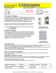
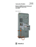
A66SM Manual A66SM Installation and Programming Manual This Manual describes the A66SM Communications Adapter for the Altivar 66 Variable Frequency Drive, its uses and set up. Effective: 22 February 1999 Niobrara Research and Development Corporation P. O. Box 3418 Joplin, MO 64803 Telephone: (800) 235-6723 or (417) 624-8918 Facsimile: (417) 624-8920 Internet: http://www.niobrara.com Altivar, SY/MAX, PowerLogic, and PNIM are trademarks of Square D. Modbus Plus is a trademark of Schneider Automation. Subject to change without notice. Niobrara Research and Development Corporation 1998. All Rights Reserved. 2 A66SM Manual Contents CONTENTS.................................................................................................................3 1 INTRODUCTION ...................................................................................................5 2 INSTALLATION ....................................................................................................7 3 OPERATION .........................................................................................................9 A66SM Manual 3 1 Introduction The A66SM communications adapter card connects an Altivar 66 variable frequency drive controller (see Figure 1 below) to a SY/MAX PowerLogic or PNIM multidrop network. It will allow the PowerLogic or PNIM bus master to adjust drive operational parameters, command, control, and monitor drive operation, and diagnose drive fault conditions. The A66SM is a Type 3 PCMCIA card with an attached 3 meter cable terminated with a 15pin D-Sub connector. The A66SM is designed to operate in the PCMCIA slot of an I/O extension module (VW3A66201T or VW3A66202T) or communication carrier module VW3A66205 (not the drive’s main PCMCIA slot), and requires drive firmware revision 3.2 or later. NOTE: This manual is not intended to be used as a guide for drive operations. It is written to explain connection of the A66SM to the PowerLogic or PNIM network, and to describe the mapping of the drive parameters into registers. For information on drive operation, refer to Instruction Bulletin VD0C06S304B (Altivar 66 User’s Manual). Figure 1: Altivar 66 variable frequency drive. A66SM Manual 5 2 Installation Refer to Section 1 of Instruction Bulletin VD0C06S308 for installation instructions for the A66SM communication card in the Altivar 66 drive controller. Please note the following additions/modifications to the Square D installation instructions: • For the A66SM communications card to operate correctly, the drive into which it is installed must have revision 3.2 or later firmware. This may be viewed on the Drive Identification menu page, for example “ATV66U41N4, CT, V3.2” • In the drive’s communications setup (Menu 11), set Protocol to Modbus+ and Address to the desired slave address. Set the Timeout to a value appropriate for the system’s scan rate. When the drive is under Serial Link Control, this timeout value will determine how long the drive will run without receiving communications from the PNIM or PowerLogic bus master before shutting down. The Peer Cop and Global Data parameters are not used and should be set to NO and zero respectively. When the card is recognized by the drive, the drive’s Comm. State menu (menu 12) will reflect the selected address and show a constantly changing token counter. • The adapter supports the SY/MAX PNIM and PowerLogic serial protocols at 9600 bits per second, 8 data bits,1 start bit, 1 stop bit, and even parity. The port settings cannot be changed in the field. The A66SM PCMCIA card has an attached cable which terminates in a 15-pin DSubminiature male plug. LAN Connection to this plug is as shown in Figure 2 on page 8. Connection to this plug may be made using Phoenix Contact part number FLKM-D 15 SUB/B, or by building a cable to make the following connections: A66SM Manual 7 IN- 8 15 7 14 6 SHIELD OUTOUT+ 13 5 12 4 11 3 IN+ 10 2 9 1 Figure 2: Connection of PowerLogic network to A66SM DB-15 connector. Two-Wire Connection The A66SM may be run on a two wire RS-485 network, with Circuit Monitors, and probably other devices which use PNIM protocol. Two wire RS-485 communication to a PowerLogic network may only be done using the PNIM protocol (PowerLogic protocol is full-duplex). To connect the A66SM to a 2-wire network, its transmit and receive pairs must be electrically connected near the connector (i.e. IN+ to OUT+ and IN- to OUT-). Thus, the (+) wire of the RS-485 network connects to both IN+ and OUT+, and the (-) wire connects to both IN- and OUT-. 8 A66SM Manual 3 Operation The essential command and monitoring parameters of the Altivar 66 drive controller are mapped into registers as described in Table 1, beginning on page 11. The most basic motor control can be accomplished using registers 2021, 2022, and 2032: NOTE: This manual references bits in the standard SY/MAX notation where the least significant bit (lsb) is bit 1 and the most significant bit (msb) is bit 16. Instruction Bulletin VD0C06S309 (Modbus+ PCMCIA manual) uses the notation of the lsb being bit 0 and the msb bit 15. Register 2021 contains a bitmap of discrete drive controls. Bits 2 and 3 of register 2021 put the drive controller in SLC (Serial Link Control) mode when set, and release the drive controller into local control mode when cleared. (NOTE: SLC mode is not available when the drive controller has its PI regulator enabled.) In SLC, the drive receives its operational parameters (speed, direction, etc.) from the A66SM, whereas in local control mode serial communications can only be used to gather data. Bit 6 of Register 2021 starts the motor when set, and stops the motor when cleared. Register 2022 sets the reference frequency (thus, speed) of the drive. Bit 2 of Register 2032, when set, commands the drive to run in the reverse direction. While in SLC mode, the drive controller will stop the motor if it does not receive valid communication from its master within the Communications Timeout interval (programmed through the keypad, in Menu 11). Bit 5 of Register 2021, when set, disables this serial link timeout feature, such that if serial communications are lost, the drive will continue to run. This mode of operation is not recommended for normal use. During loss of control, it is almost always safest for the operation to cease until repairs can be made. A communications timeout fault, or any other resettable fault can be cleared by setting Bit 1 of register 2021. This bit will automatically return to 0 after being set. For further information on register significance, and drive operation refer to Instruction Bulletin VD0C06S309 (Modbus+ PCMCIA manual). The A66SM card has two LED indicators. The green indicator will flash as PNIM or SY/MAX communications packets are received. The red indicator will flash if a packet or A66SM Manual 9 command is in error or otherwise not recognized by the card. If the last message sent to the card has an error, the red light may stay on until a new, good, packet is received. Errors which will light the red LED include: Checksum error, inter-character timeout error, attempt to read or write an unsupported or illegal register, or an illegal SY/MAX opcode. 10 A66SM Manual Table 1: Register map for the A66SM Address Bit Description 2001 2002 2003 2004 2005 2006 2007 2008 2009 2010 2011 2012 2013 2021 --------------------------1 2 3 4 5 6 7 8 9 10 11 12 13 15 16 --2-4, 7-9 --------------- High Speed Low Speed Accel 1 Decel 1 Accel 2 Decel 2 Slip Compensation IR Compensation Profile Voltage Boost Damping Bandwidth Motor Overload Drive Reset Assignment of logic commands over link (DLI) Assignment of references over link (FLI) Alternate ramps (Ramp 2) Suppression of communication control (NTO) Run/Stop Command Braking by DC injection (DCB) Orient Stop Freewheel Stop Fast Stop Command of voltage reduction Multi-Motors Multi-Parameters External fault command (EFL) Peer Cop Adjustment storage Reference Frequency Command of LOx / ROx state Command of AO1 Level Current Limit level Motoring torque limit level Regenerating torque limit level Voltage reduction level Command of AO2 level Command of AO3 level 2022 2023 2024 2025 2026 2027 2029 2030 2031 A66SM Manual 11 Table 1: Register map for the A66SM (cont’d) 2032 2041 2042 2043 2044 2045 2046 2047 2048 12 1 2 4 9 1 2 3 4 5 6 7 8 9 10 11 12 13 15 16 ----2-9 10-11 12-15 ------1 2 3 4 5 6 7 8 9 10 11 12 14 15 16 Command of current limit Run direction Command of torque limit Elapsed timer reset Mode in which all commands are assigned Drive controller ready (RDY or SLC) Fault (FLT) Reset authorized Brake engage relay state Forced local NTO Resettable fault Motor running Actual rotation direction DC injection braking Steady state Motor thermal overload alarm Current limit No line power (NLP) Output frequency Output current Display of logic input activation (LI1 - LI8) Display of logic output activation (LO1 - LO2) Display of relay activation (R1 - R4) Value of analog input (AI1) Motor torque Speed reference Local command mode T/K Logic commands over link (DLI) Reference commands over link (FLI) Dynamic braking Fast stop Power loss, ramp stop Gating state Orient complete Deceleration (DEC) Acceleration (ACC) Multi-motor or Multi-parameter selected Drive controller thermal fault Torque limit Stopping by the keypad A66SM Manual Table 1: Register map for the A66SM (cont’d) 2049 2050 2051 2052 2053 2054 2055 2056 2057 2058 2059 2060 2061 2062 2063 2064 2065 2066 2067 2068 2069 2070 2072 2075 2076 2077 A66SM Manual 1 2 3 4 5 6 7 8 9 10 11 12 13 14 1 5 6 ------------------------------------------------- Jog Shutdown complete Cycle complete Alternate ramp Auto/Manual Frequency level 1 attained Frequency level 2 attained Current level 1 attained Current level 2 attained Thermal level 1 attained Thermal level 2 attained No ramp follow Run output command Rotation direction Drive faulted, stopped State of adjustment semaphore State of command semaphore Display of fault causing trip Display of present faults Output power Output voltage Line voltage Bus voltage Motor thermal state value Drive controller thermal state value Elapsed time (hours) Elapsed time (minutes) Output speed (rpm) Machine frequency reference number (customer units) Machine frequency (customer units) Value of analog input AI2 Value of analog input AI3 Value of analog input AI4 Value of AO1 Value of AO2 Value of AO3 Speed ramp output Nominal motor voltage range Number of motor or parameter set selected Cycles step number in progress Preset speed number in progress 13 Table 1: Register map for the A66SM (cont’d) 2101 2102 2103 2104 2105 2106 2107 2108 2109 2112 2113 2114 2115 2116 2117 2118 2119 2120 2121 2122 2123 2141 2142 2143 2144 2145 2146 2147 2148 2149 2150 2151 2152 2153 2154 2155 2156 2157 14 ----------------------------------------------------------------------------- Assignment of AI1 Assignment of AI2 Assignment of AI3 Assignment of AI4 Assignment of AO1 Assignment of AO2 Assignment of AO3 Assignment of LO1 Assignment of LO2 Assignment of R1 Assignment of R2 Assignment of R3 Assignment of R4 Assignment of LI1 Assignment of LI2 Assignment of LI3 Assignment of LI4 Assignment of LI5 Assignment of LI6 Assignment of LI7 Assignment of LI8 Indicates the position of marker on 1 of 8 past faults Past fault 1: Drive controller state Past fault 1: Name of fault Past fault 2: Drive controller state Past fault 2: Name of fault Past fault 3: Drive controller state Past fault 3: Name of fault Past fault 4: Drive controller state Past fault 4: Name of fault Past fault 5: Drive controller state Past fault 5: Name of fault Past fault 6: Drive controller state Past fault 6: Name of fault Past fault 7: Drive controller state Past fault 7: Name of fault Past fault 8: Drive controller state Past fault 8: Name of fault A66SM Manual Table 1: Register map for the A66SM (cont’d) 2201 2202 2203 2204 2205 2206 2207 2212 2213 2214 2215 2217 A66SM Manual ------------------------- Drive controller horsepower (hardware rating) Drive controller horsepower (configured rating) Drive controller voltage range Line frequency recognized Drive controller maximum rated frequency Drive controller nominal current Drive controller maximum current Memory card option Communication carrier option Presence of keypad I/O Extension option card PCMCIA communication card 15