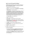
1
User manual
Cordless Twin Port
HW 8612 DECT
HW 8612/US FHSS
Version 1.05
This document and its contents shall not be reproduced or transferred in any form without express permission.
Compensation will be claimed for any infringement. All rights reserved in the event of patenting or registration of utility
models.
© Höft & Wessel AG 2001
Subject to amendment, errors excepted
HW8612engA4_V1.05.doc
TABLE OF CONTENTS
Table of contents
1. Introduction................................................................................................................. 5
1.1
1.2
1.3
1.4
References ............................................................................................................. 5
Important user information...................................................................................... 6
Special note for users in the USA (HW 8612/US only) .......................................... 7
Important Information for users in Canada (HW 8612/US only) ............................. 7
2. Product description.................................................................................................... 8
2.1
2.2
2.3
2.4
Operational elements ............................................................................................. 8
Technical specification – HW 8612 ........................................................................ 9
Technical specification - HW8612/US .................................................................. 10
Included delivery................................................................................................... 11
3. Installation................................................................................................................. 12
3.1 Data Unwired system architecture........................................................................ 12
3.1.1 Wireless Internet access via ISDN (DECT only) ............................................ 13
3.1.2 Wireless Internet access via analogue modem lines (DECT only) ................. 13
3.1.3 Wireless server or shared peripheral access ................................................. 14
3.2 Hardware installation ............................................................................................ 15
3.2.1 Getting the best radio coverage ..................................................................... 15
3.3 LED display information........................................................................................ 16
4. Taking HW 8612 into operation ............................................................................... 17
4.1 Setting-up your computer ..................................................................................... 17
4.2 Subscribing the HW 8612 to a base station.......................................................... 17
4.3 Configuration using the Data Unwired Configurator ............................................. 18
4.3.1 Installation of the Data Unwired Configurator................................................. 18
4.3.2 Using the Data Unwired Configurator............................................................. 19
4.4 Configuration using a terminal program................................................................ 21
4.4.1 Entering and leaving the configuration mode ................................................. 21
4.4.2 Performing the subscription ........................................................................... 22
4.4.3 Setting the base station’s PIN code ............................................................... 22
4.4.4 Advanced configuration.................................................................................. 23
5. Using the HW 8612 ................................................................................................... 24
6. Appendix ................................................................................................................... 25
6.1 Serial port pinout .................................................................................................. 25
6.2 Current consumption diagrams ............................................................................ 26
6.2.1 HW 8612 ........................................................................................................ 26
6.2.2 HW 8612/US .................................................................................................. 26
6.3 Manufacturer address........................................................................................... 27
6.4 Troubleshooting.................................................................................................... 28
6.4.1 Power supply.................................................................................................. 28
6.4.2 Availability of a base station........................................................................... 28
6.4.3 Erroneous configuration mode ....................................................................... 29
6.4.4 No connection ................................................................................................ 29
6.4.5 The HW 8612 does not enter the configuration mode.................................... 30
6.4.6 Subscription to the base station fails.............................................................. 30
7. Index of figures ......................................................................................................... 31
1.05 • 30.07.2004 3
TABLE OF CONTENTS
8. Index .......................................................................................................................... 31
9. Notes.......................................................................................................................... 33
4
1.05 • 30.07.2004
INTRODUCTION
1.
Introduction
Thank you for choosing Data Unwired products of Hoeft & Wessel.
The HW 8612 cordless twin port is a powerful solution for cordless data
communication when replacing V.24 cables by a radio connection in order to
address different peripheral devices via common interface.
Data Unwired products operate according the international DECT
telecommunication standard resp. the North American FCC and the Canadian
standard.
•
DECT offers a reserved radio spectrum which is free from interference.
Operation of Data Unwired DECT systems is unrestricted and licence-free in all
countries of the EU.
•
Data Unwired FHSS (Frequency Hopping Spread Spectrum) systems operate in
the open 2.4 GHz band and comply with FCC part 15.
Data Unwired products are easy to install and do not require specific drivers. So
they can be used with most computers and operating systems.
This manual describes how to install and use the HW 8612 cordless twin port.
In case of problems during the installation or during the operation of the HW 8612
that cannot be solved with the information given in this manual, please contact the
service department of your local dealer or contact the Hoeft & Wessel-service line
directly at
[email protected].
For further information about Data Unwired products please visit our Website:
www.data-unwired.com
1.1
References
Please follow the explanation and instructions in the Integration Manual IM86010
and Firmware Manual FM86010, too.
In the case of inconsistency the documents apply in the following order of priority:
1. Firmware Manual FM86010, 2. Integration Manual IM86010, 3. this manual.
1.05 • 30.07.2004 5
INTRODUCTION
1.2
Important user information
The HW 8612 does not require maintenance work or special attendance, except for
the instructions mentioned below.
CAUTION!
Do not operate device within the range of strong electromagnetic fields.
Notice the temperature range for operation given in chapter 2.2. Do especially
avoid overheating.
Protect device against humidity and dust.
Do clean device only with a soft cloth and mild cleaning agent. Do not apply
water or wet cleaner.
Do not insert any objects into openings of the device unless specifically
mentioned otherwise in this document. This may damage the device.
Do not open the HW 8612
The HW 8612 does not contain parts which could be maintained, exchanged
or repaired by the customer or non-authorised maintenance personnel.
Opening
the
device
might
damage
the
electric
A correct function of the device is no longer guaranteed!
components.
Only operate the HW 8612 with the enclosed AC adapter
The HW 8612 is delivered with an AC adapter. Using any other power supply
may damage the device or cause radio interference.
Before connecting the AC adapter make sure that the voltage fits the local
power supply.
6
1.05 • 30.07.2004
INTRODUCTION
1.3
Special note for users in the USA (HW 8612/US only)
NOTE:
This equipment has been tested and found to comply with the limits for a
Class B digital device, pursuant to Part 15 of the FCC Rules. These limits are
designed to provide reasonable protection against harmful interference in a
residential installation. This equipment generates, uses and can radiate radio
frequency energy and, if not installed and used in accordance with the
instructions, may cause harmful interference to radio communications.
However, there is no guarantee that interference will not occur in a particular
installation. If this equipment does cause harmful interference to radio or
television reception, which can be determined by turning the equipment off
and on, the user is encouraged to try to correct the interference by one or
more of the following measures:
•
•
•
Reorient or relocate the receiving antenna.
Increase the separation between the equipment and receiver.
Connect the equipment into an outlet on a circuit different from that to
which the receiver is connected.
•
Consult the dealer or an experienced radio/TV technician for help.
The maximum output power of the Base Station transmitter is 100 mW. Though this is a low power level
a minimum separation distance of 20 cm from the enclosure of the Base Station to all persons must be
kept. The antennas must not be co-located and operating in conjunction with any other antenna or
transmitter.
1.4
Important Information for users in Canada (HW 8612/US only)
NOTE!
To prevent radio interference to the licensed service, this device is intended
to be operated indoors and away from windows to provide maximum
shielding. Equipment (or its transmit antenna) that is installed outdoors is
subject to licensing.
1.05 • 30.07.2004 7
PRODUCT DESCRIPTION
2.
Product description
2.1
Operational elements
Höft & Wessel
Push button
LED 1
LED 2
Figure 1: HW 8612 top view
Push
Button
Pressing this button activates the on-air subscription procedure
LED1
LED2
The two LEDs indicate the operational state of the device
DC in
COM-MOD
COM-PC
Figure 2: HW 8612 back view
COM-PC
Connect the HW 8612 to your computer with the enclosed serial
data cable
COM-MOD Connect the HW 8612 to your Modem with the enclosed serial
data cable
DC in
8
Connect the HW 8612 with the AC adapter (included in the
delivery)
1.05 • 30.07.2004
PRODUCT DESCRIPTION
2.2
Technical specification – HW 8612
Dimensions:
Weight:
Temperature range:
Power supply:
Interfaces:
Frequency:
Output power:
Standards:
Conformity:
Modulation:
Data capacity:
Antenna system:
Range:
Operational elements:
Casing:
Accessories:
approx. 145 x 88 x 46 mm
approx. 180 g
0 .. +55 °C operating
6.0 .. 10.0 V, 300 mA
RS-232, 115 kBd (max)
2 serial interfaces (9-pin Sub-D connectors, V.24)
1.880 .. 1.900 MHz
250 mW (max.)
EN 300 175 parts (DECT Common Interface)
EN 301 406 (TBR6 2nd edition)
ETS 300 329 (EMC for DECT equipment)
ETS 300 651 (Data Services DSP C.2)
DECT CTR 6
Gaussian FSK
115.2 kBd max., protected
two integrated antennas,
external connector opt.
up to 60 m inhouse, up to 300 m outdoor
1 push button
2 LEDs
plastic housing, suitable for wall mount or desktop
installation
external power supply unit HW 1202, 240V/50Hz prim.,
6.0 V/300 mA sec., V.24 data cable
1.05 • 30.07.2004 9
PRODUCT DESCRIPTION
2.3
Technical specification - HW8612/US
Dimensions:
Weight:
Temperature range:
Power supply:
Interfaces:
Frequency:
Output power:
Standards:
Modulation:
Mode:
Duty cycle:
Data capacity:
Antenna system:
Range:
Operational elements:
Casing:
Accessories:
10
1.05 • 30.07.2004
approx. 145 x 88 x 46 mm
approx. 180 g
0 .. +55 °C operating
6.0 .. 10.0 V, 300 mA
RS-232, 115 kBd (max)
2 serial interfaces (9-pin Sub-D connectors, V.24)
2.400 .. 2.483 GHz
100 mW
EN 300 328
FCC part 15 (Low power devices operating in
2400 MHz band)
EN 300 175 parts 4 - 6
(DECT Common Interface)
ETS 300 329 (EMC for DECT equipment)
ETS 300 651 (Data Services DSP C.2)
Gaussian FSK
FHSS
max. 16.67 %
115.2 kBd max., protected
two integrated antennas, external connector opt.
up to 60 m inhouse, up to 300 m outdoor
1 push button
2 LEDs
plastic housing, suitable for wall mount or desktop
installation
external power supply unit, UL1310 (class 2),
120V/60Hz prim.,
7.5 V/600 mA sec.,
V.24 data cable
2.4
Included delivery
The device is shipped with the following components:
•
HW 8612 or HW 8612/US
•
Power supply unit
•
1 serial data cable
•
Configuration software
1.05 • 30.07.2004 11
INSTALLATION
3.
Installation
3.1
Data Unwired system architecture
The HW 8612 cordless twin port acts as a mobile station of a Data Unwired system.
Every Data Unwired system requires a base station and may contain one ore more
mobile stations.
If you purchased the HW 8612 as part of a communication set the base station is
included.
Single HW 8612 devices are also available, in case you want to extend an existing
Data Unwired installation with an additional mobile station.
Different base stations are available that offer dedicated connectivity:
12
Data Unwired ISDN
HW 8621 (DECT only)
Base station for Internet access via ISDN
Data Unwired Modem
HW 8622 (DECT only)
Base station for Internet access via analogue modem
lines
Data Unwired Base
HW 8612
Base station for access to a shared peripheral device or
a server computer
via serial interface
1.05 • 30.07.2004
INSTALLATION
3.1.1
Wireless Internet access via ISDN (DECT only)
HW 8612
ISDN S0
HW 8612
HW 8621
Figure 3: Wireless Internet access via ISDN
The basic system comprises a single HW 8612 cordless twin port together with an
ISDN base station HW 8621. The system may be expanded so multiple PCs can
use the base station alternately.
3.1.2
Wireless Internet access via analogue modem lines (DECT only)
HW 8612
line
HW 8612
HW 8622
Figure 4: Wireless Internet access via analogue modem lines
The basic system comprises a single HW 8612 cordless twin port together with a
modem base station HW 8622. The system may be expanded so multiple PCs can
use the base station alternately.
1.05 • 30.07.2004 13
INSTALLATION
3.1.3
Wireless server or shared peripheral access
HW 8612
HW 8612
server
HW 8612
Figure 5: Wireless server or shared peripheral access
The basic system comprises a single HW 8612 cordless twin port together with a
V.24 base station HW 8612. The system may be expanded so multiple PCs can use
the base station alternately.
14
1.05 • 30.07.2004
INSTALLATION
3.2
Hardware installation
This chapter deals with the hardware installation of the HW 8612. In case you
purchased it together with a base station in a communication set, base station and
HW8612 are ready for communication.
In order to establish a data connection to your computer, please connect the
enclosed
V.24
data
cable
to
the
V.24
port
of
the
HW 8612 and to a COM port of your computer.
The cable fits to 9-pin COM port. Some older computers still have 25-pin COM port
connectors.
In
this
case
you
will
need
a
9 (male) / 25 (female) sub-D adapter, which is available from your local dealer.
For power supply, first connect the AC adapter to the HW 8612. Before plugging it
into the mains, check that your local supply voltage fits to the voltage range printed
on the AC adapter.
3.2.1
Getting the best radio coverage
Like any radio device the coverage range of the HW 8612 is limited by the available
transmit power and losses on the radio path.
Data Unwired can bridge distances up to 300m in open space. In real environments
the range is influenced by shielding, reflections and interference. In a typical indoor
environment like an apartment, a range up to 60m can be expected. In order to
achieve these results, take care where you locate your radio devices (i.e. mobile
and base stations).
•
•
•
•
•
Operate the radio device in a dry and clean place on moderate temperatures.
Keep the device away from heat sources.
Do not place the radio device close to large metal objects.
Each object in between the mobile and the base station will attenuate the radio
waves.
Try to install the base station as high above ground as possible, since most
obstacles are on the ground.
Walls will attenuate the radio signal. Light walls have only little impact whereas
armed concrete absorbs most of the radio energy. Try to achieve a line-of-sight
condition between the mobile and the base station.
1.05 • 30.07.2004 15
INSTALLATION
3.3
LED display information
When the HW 8612 is powered-on, one or both of the LEDs will light-up in intervals
or continuously. This signals the operational state of the device. The meaning of the
different LED displays is further explained below
LED1
(red)
16
LED2
Meaning
(green)
•
•
Power off condition
•
☼☼••
Power on, not locked to a base station
(slow blink)
•
☼
☼
☼
End-to-end connection established. The exact meaning on LED1
depends on the function of the base station.
☼
•
Device has entered configuration mode.
☼•☼•
•☼•☼
On-air subscription in progress
(fast alternating blink)
☼•☼•
•
On-air subscription failure (fast blink)
•
☼•☼•
On-air subscription success (fast blink)
DECT connection to base station established
While data is transmitted, LED2 flickers.
1.05 • 30.07.2004
TAKING HW 8612 INTO OPERATION
4.
Taking HW 8612 into operation
This chapter describes the basic configuration of the HW 8612 cordless twin port.
More advanced configuration features are provided, but generally not required in
typical applications.
4.1
Setting-up your computer
As a default, the V.24 port of the HW 8612 is configured to
115.200 Bd
8 data bits
no parity
1 stop bit
RTS/CTS handshake on
You must configure the COM port on your computer for these settings.
On Windows operating systems, applications usually do not directly access the
COM port. Take care to set up the baud rate at the right place. If you use the HW
8612 together with an ISDN base station HW 8621 or a modem base station HW
8622 you must set up the baud rate under Settings / Modems. A detailed
description can be found in the user manual of the respective base station
4.2
Subscribing the HW 8612 to a base station
A mobile station only works with a base station where it has been subscribed. This
is a security feature of your Data Unwired system that prevents access from
unauthorised devices. It also applies to the HW 8612.
During the subscription procedure the HW 8612 and the associated base station
agree on a secret key that is then used for data encryption. The key depends on
unique hardware addresses of base and mobile stations and a PIN code to be
configured by the user.
Unless the pin code of the system is changed, the subscription procedure must be
done only once during the installation of each mobile station.
1.05 • 30.07.2004 17
TAKING HW 8612 INTO OPERATION
4.3
Configuration using the Data Unwired Configurator
The delivery encloses a configuration software tool that simplifies configuration of
Data Unwired products. The Data Unwired Configurator requires a Win98, WinNT,
WinME or Win2000 operating system.
Usage of this tool is highly recommended because it makes configuration easier
and also includes a self check of the system. However, configuration can also be
made without this utility, e.g. if the HW 8612 is connected to a non-Windows system
(4.4).
4.3.1
Installation of the Data Unwired Configurator
Start the application DUConf.exe from hard disk, your provided disk or CD ROM
and follow the instructions given in section 4.3.2.
18
1.05 • 30.07.2004
TAKING HW 8612 INTO OPERATION
4.3.2
Using the Data Unwired Configurator
Step 1: Welcome
Click button [Next]
Step 2: Connect base station
Connect the base station to a COM port of your
PC. Select the COM port in the dialog box.
Click button [Next].
Step 3: Base station settings
Enter a baud rate and PIN of your choice. The
PIN is stored inside the Configurator for easier
re-use.
Click button [Next].
The base station is ready now.
1.05 • 30.07.2004 19
TAKING HW 8612 INTO OPERATION
Step 4: Connect mobile station
Disconnect the base station from your PC, but
leave it powered-on.
Connect the HW 8612 to a free COM port of your
PC and select that COM port in the dialog box.
Click button [Next].
Step 5: Perform subscription of the mobile
station
Press the push button on the base station for
about 5 seconds until the two LEDs are blinking
alternately. The base station is now ready to
accept a subscription of the mobile station.
Click button [Next].
This will trigger the subscription procedure.
Step 6: Ready
After a successful subscription the base station's
green LED will start blinking quickly for 5
seconds, then turn to blinking slowly.
The radio set is ready for wireless
communication now. If you want to subscribe
another mobile station to the same base, click
button [Another]. Otherwise click [Exit] to
terminate the Configurator program.
When ready, please reset both base and mobile
station by disconnecting them from the power
supply
for 5 seconds.
20
1.05 • 30.07.2004
TAKING HW 8612 INTO OPERATION
4.4
Configuration using a terminal program
This method must be used, if you configure the HW 8612 on a non-Windows
computer, or in case you want to perform advanced configuration commands.
Please set-up your computer as described in section 4.1.
Start
a
HW 8612.
4.4.1
terminal
program
on
your
computer
and
access
the
Entering and leaving the configuration mode
The HW 8612 has a configuration mode. In this mode it can be configured using
simple text-based command.
To start the configuration mode, enter the key sequence + - + on the terminal
program. The following timing requirements apply:
•
•
Before the first + character and after the last + character there must be a pause
of at least 500 ms
Between two characters of the escape sequence the maximum allowed pause
is 200 ms
The red LED1 will light up which indicates that the HW 8612 is in configuration
mode. In this mode the HW 8612 will response to commands received via the V.24
interface.
All commands have to be terminated by [↵] (RETURN key).
When keying in the command EXIT the configuration mode will be terminated.
1.05 • 30.07.2004 21
TAKING HW 8612 INTO OPERATION
4.4.2
Performing the subscription
Please make sure the HW 8612 is connected to the power supply as well as to your
terminal program and is properly set to configuration mode (see 4.4.1). Please
ensure the base station is also connected to its power supply.
Please press the push button of the base station until the two LEDs start blinking
fast and alternately.
Enter the command
SISUA <pin>
- where <pin> is the PIN code of your base station. For instructions how to set the
PIN code of the base station please refer to the next section.
Example:
SISUA 0
Note that leading zeros of PIN codes are relevant, e.g. PIN code 0 is different from
PIN code 000.
After successful subscription the green LED on the HW 8612 and the base station
will start blinking fast.
Leave the configuration mode by use of the command
EXIT
4.4.3
Setting the base station’s PIN code
Please make sure the base station is connected to the power supply as well as to
your terminal program and is properly set to configuration mode.
Please enter the command
SIPIN <pin>
Leave the configuration mode by use of the command
EXIT
22
1.05 • 30.07.2004
TAKING HW 8612 INTO OPERATION
4.4.4
Advanced configuration
This document describes only the basic configuration of the Cordless Twin Port. All
Data Unwired products can be customized by using special commands. For detailed
information about advanced configuration of Data Unwired products please contact
your
service
department
of
your
local
dealer
or
contact
the
Hoeft & Wessel service line directly at
[email protected]
1.05 • 30.07.2004 23
USING THE HW 8612
5.
Using the HW 8612
After
the
HW
8612
has
been
Data Unwired system is ready to be used.
taken
into
operation,
A
cordless
data
connection
to
the
base
station
automatically
established
when
your
computer
activates
DTR
line
of
the
COM-port.
Typical
PC
applications
the DTR signal as soon as they allocate a COM-port.
your
is
the
set
When the wireless data connection is no longer needed, the application clears the
DTR signal and the wireless data connection is released.
24
1.05 • 30.07.2004
APPENDIX
6.
Appendix
6.1
Serial port pinout
DC in
COM-MOD
COM-PC
Figure 6: HW 8612 back view
COM-PC
Pin no.
1
2
3
4
5
6
7
8
9
RS232 signal
DCD out
RXD out
TXD in
DTR in
GND
DSR out
RTS in
CTS out
RI out
5 4 3 2 1
9 8 7 6
COM-MOD
Pin no.
1
2
3
4
5
6
7
8
9
RS232 signal
DCD in
RXD in
TXD out
DTR out
GND
DSR in
RTS out
CTS in
RI in
1 2 3 4 5
6 7 8 9
1.05 • 30.07.2004 25
APPENDIX
6.2
Current consumption diagrams
6.2.1
HW 8612
mA
700
600
500
400
300
200
100
0
0
2
4
6
8
10
11
12
13
14
ms
Figure 7: HW8612 typical consumption diagram (4 bearers in use)
6.2.2
HW 8612/US
mA
700
600
500
400
300
200
100
0
0
2
4
6
8
10
11
12
13
14
ms
Figure 8: HW8612/US typical consumption diagram (4 bearers in use)
26
1.05 • 30.07.2004
APPENDIX
6.3
Manufacturer address
Hoeft & Wessel AG
Rotenburger Str. 20
D - 30659 Hannover
Phone:
+49 511 / 6102 - 0
Fax: +49 511 / 6102 - 411
www.hoeft-wessel.com
[email protected]
www.hoeft-wessel.de
[email protected]
www.data-unwired.com
Service line: +49 / 1803 / 23 28 29
1.05 • 30.07.2004 27
APPENDIX
6.4
Troubleshooting
6.4.1
Power supply
Make sure that the HW 8612 is properly connected to the AC connector which is
plugged to the mains. When the device is powered, at least one of the LEDs will
light up or blink.
In case both LEDs remain dark, a problem with the power supply is the most likely
reason.
•
Please unplug the device from the power supply and re-connect it.
If the problem persists please contact the Hoeft & Wessel service line for further
support.
6.4.2
Availability of a base station
A slow blinking red LED indicates that the HW 8612 is not able to find a base
station. This may have several reasons.
•
•
•
Check the power supply of the base station. Please refer to the base station
documentation for further details
Maybe the coverage range of the base station is exceeded. In this case the
problem will disappear as you get closer to the base station. Follow the
instructions in section 3.2.1 to improve the coverage range of your system.
The subscription information of the HW 8612 is invalid. Try to renew the
subscription as described in section 4.2.
If you cannot solve the problem with these hints, please consult the Hoeft & Wessel
service line.
28
1.05 • 30.07.2004
APPENDIX
6.4.3
Erroneous configuration mode
A continuously lit red LED indicates that the device is in configuration mode. In this
mode it will not set up a connection to the base station.
The configuration mode is left by use of the EXIT command (see section 4.4.1). An
alternate way to quit the configuration mode is to simply execute a power-off/poweron reset.
If such a problem occurs frequently you should consult the Hoeft & Wessel service
line.
6.4.4
No connection
A slow blinking green LED on the HW 8612 indicates that it has found a base
station. In this state it should be able to establish a wireless data connection. If
there is no connection, please check the following possible causes:
•
•
•
•
Verify that the V.24 cable from your computer to the HW 8612 is correctly
connected.
Make sure that the PC COM port is set-up correctly (see section 4.1).
Check that the application running on your computer has opened the COM port
and set the DTR signal.
Verify that the base station is ready to accept a connection. Please refer to
chapter 4.2 for further information.
In case the problem persists, you should consult the Hoeft & Wessel service line.
1.05 • 30.07.2004 29
APPENDIX
6.4.5
The HW 8612 does not enter the configuration mode
Although
you
followed
the
instructions
in
section
4.4.1,
the
HW 8612 does not enter the configuration mode. Most likely there is a problem with
the V.24 connection between your computer and the HW 8612. Please proceed as
follows:
•
•
•
6.4.6
Make sure that the device is powered-up.
Verify that the V.24 cable from your computer to the HW 8612 is correctly
connected.
Make sure that the PC COM port is set-up correctly (see section 4.1).
Subscription to the base station fails
•
•
•
•
Check that you use the correct PIN
Verify that both devices are powered-up
The base station must be set to subscription mode, which is indicated by fast
and alternately blinking green and red LEDs
Make sure not to exceed the coverage range
In case the problem persists please consult the Hoeft & Wessel service line.
30
1.05 • 30.07.2004
INDEX OF FIGURES
7.
Index of figures
Figure 1: HW 8612 top view ............................................................................................................................ 8
Figure 2: HW 8612 back view.......................................................................................................................... 8
Figure 3: Wireless Internet access via ISDN ................................................................................................. 13
Figure 4: Wireless Internet access via analogue modem lines...................................................................... 13
Figure 5: Wireless server or shared peripheral access.................................................................................. 14
Figure 6: HW 8612 back view........................................................................................................................ 25
Figure 7: HW8612 typical consumption diagram (4 bearers in use) .............................................................. 26
Figure 8: HW8612/US typical consumption diagram (4 bearers in use) ........................................................ 26
8.
Index
ISDN 12
—A—
AC adapter 8
AC connector 28
analogue modem 12
—L—
LED 22, 29
LEDs 22, 28, 30
—B—
—M—
base station 12, 17, 19, 20, 22, 28, 29
baud rate 17, 19
mobile station 12, 17
mobile stations 17
Modem 8
—C—
Canada 7
CD ROM 18
COM port 15, 17, 29, 30
configuration mode 21, 22, 29, 30
Configuration software 11
connectivity 12
consumption diagram 26
continuously 16
cordless 5
CTR 6 9
—N—
non-Windows 21
non-Windows system 18
—O—
on-air subscription 8
open space 15
operating system 18
operating systems 5, 17
—D—
—P—
data encryption 17
DECT 5, 9, 10, 12, 16
drivers 5
DTR signal 24, 29
—E—
peripheral 5
PIN 19, 22, 30
pin code 17
power supply 22, 28
Power supply unit 11
push button 22
escape sequence 21
EU 5
—R—
—F—
FCC 5
FHSS 5
—I—
radio 5
—S—
serial data cable 8
service line 27, 28, 29, 30
subscription 22, 28
subscription mode 30
indoor 15
interface 5
interference 5
1.05 • 30.07.2004 31
INDEX
—T—
V.24 interface 21
terminal program 21, 22
timing requirements 21
—W—
—U—
unauthorised 17
Unwired 5
USA 7
—V—
V.24 29, 30
32
1.05 • 30.07.2004
Win2000 18
Win98 18
Windows 17
WinME 18
WinNT 18
wireless 24, 29
wireless communication 20
NOTES
9.
Notes
1.05 • 30.07.2004 33