1
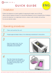
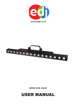
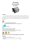
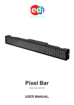
APMC4110 POWERED PMC CARRIER
STANDALONE PCI INTERFACE MODULE
USER’S MANUAL
ACROMAG INCORPORATED
30765 South Wixom Road
P.O. BOX 437
Wixom, MI 48393-7037 U.S.A.
Copyright 2010, Acromag, Inc., Printed in the USA.
Data and specifications are subject to change without notice.
Tel: (248) 295-0310
Fax: (248) 624-9234
8500-899-A10L000
2
APMC4110 User’s Manual
Standalone PMC Carrier
__________________________________________________________________
TABLE OF
CONTENTS
The information of this manual
may change without notice.
Acromag makes no warranty
of any kind with regard to this
material, including, but not
limited to, the implied
warranties of merchantability
and fitness for a particular
purpose. Further, Acromag
assumes no responsibility for
any errors that may appear in
this manual and makes no
commitment to update, or
keep current, the information
contained in this manual. No
part of this manual may be
copied or reproduced in any
form without the prior written
consent of Acromag, Inc.
IMPORTANT SAFETY CONSIDERATIONS
You must consider the possible negative effects of power, wiring,
component, sensor, or software failure in the design of any type of
control or monitoring system. This is very important where property
loss or human life is involved. It is important that you perform
satisfactory overall system design and it is agreed between you and
Acromag, that this is your responsibility.
1.0
1.1
1.2
1.3
1.4
GENERAL INFORMATION
FIELD I/O CONNECTORS
POWER
MANUAL RESET
XILINX JTAG PORT
3
3
6
6
6
2.0
2.1
2.2
2.3
PREPARATION FOR USE
UNPACKING AND INSPECTION
INSTALLATION CONSIDERATIONS
NON-ISOLATION CONSIDERATIONS
8
8
8
8
3.0 SERVICE AND REPAIR ASSISTANCE
3.1 PRELIMINARY SERVICE PROCEDURE
3.2 WHERE TO GET HELP
9
9
9
4.0 SPECIFICATIONS
4.1 PHYSICAL
4.2 ENVIRONMENTAL
4.3 POWER REQUIREMENTS
10
10
10
10
CERTIFICATE OF VOLATILITY
11
Trademarks are the property of their respective owners.
________________________________________________________________________
Acromag, Inc. Tel:248-624-1541 Fax:248-624-9234 Email:[email protected] http://www.acromag.com
APMC4110 User’s Manual
Standalone PMC Carrier
___________________________________________________________________
3
1.0 General Information
The Acromag APMC4110 Powered PMC Carrier is a board that functions as a stand-alone PCI
interface. Using an external power supply, the carrier allows any industry standard PMC module to
be mounted without an accompany processor. The user has full access to the field I/O via two 50pin ribbon cable connectors, P1 and P2. A 14-pin Xilinx JTAG connector is also available for
utilizing boundary scan debugging. A manual reset button allows the user to force a RST# signal
when needed. An on-board DC-DC converter creates +3.3VDC from the external +5VDC source,
lowering the number of external power connections required.
1.1 FIELD I/O CONNECTORS
The PMC module’s connections are made to the Acromag APMC4110 carrier field I/O
connections through the P1 and P2 50-pin connectors. The connections are terminated as defined
within the PCI specification. The reset and clock signals are sourced from the APMC4110. In
addition, power is provided to the PMC module through the APMC4110 Carrier board.
The field I/O connections are made via two 50 pin ribbon cable connectors. Table 1.1 indicates
the pin assignments for the field I/O signal mapping of the Powered PMC Carrier board for
connector P1. Table 1.2 indicates the pin assignments for the field I/O signal mapping of the
Powered PMC Carrier board for connector P2. The field I/O signals are split equally between the
two connectors.
The diagram below shows how the pins on the I/O pins in the tables correspond to the P1 and
P2 connectors on the Powered PMC Carrier module.
Note: Notice the notch on the top side of the connector. Pin 1 is indicated with a square pad.
The odd pins are in order on the top row from right to left, as shown. The even pins are in order on
the bottom row from right to left.
Pin 49
Pin 1
Pin 50
Pin 2
________________________________________________________________________
Acromag, Inc. Tel: 248-295-0310 Fax:248-624-9234 Email:[email protected] http://www.acromag.com
4
APMC4110 User’s Manual
Standalone PMC Carrier
__________________________________________________________________
Pin Description
Differential Ch0+ (1)
COMMON
Differential Ch1+ (3)
Differential Ch2+ (5)
COMMON
Differential Ch3+ (7)
COMMON
Differential Ch4+ (9)
Differential Ch5+ (11)
COMMON
Differential Ch6+ (13)
COMMON
Differential Ch7+ (15)
Differential Ch16+ (33)
COMMON
Differential Ch17+ (35)
COMMON
Differential Ch18+ (37)
Differential Ch19+ (39)
COMMON
Differential Ch20+ (41)
Differential Ch21+ (43)
COMMON
Differential Ch22+ (45)
Differential Ch23+ (47)
Connector P1
Pin
Pin Description
1
Differential Ch0- (2)
3
COMMON
5
Differential Ch1- (4)
7
Differential Ch2- (6)
9
COMMON
11
Differential Ch3- (8)
13
COMMON
15
Differential Ch4- (10)
17
Differential Ch5- (12)
19
COMMON
21
Differential Ch6- (14)
23
COMMON
25
Differential Ch7- (16)
27
Differential Ch16- (34)
29
COMMON
31
Differential Ch17- (36)
33
COMMON
35
Differential Ch18- (38)
37
Differential Ch19- (40)
39
COMMON
41
Differential Ch20- (42)
43
Differential Ch21- (44)
45
COMMON
47
Differential Ch22- (46)
49
Differential Ch23- (48)
Pin
2
4
6
8
10
12
14
16
18
20
22
24
26
28
30
32
34
36
38
40
42
44
46
48
50
Table 1.1: Powered PMC Carrier Board Field I/O Pin Connections for P1
Note that the number in parenthesis corresponds to rear I/O PMC P4 pin number.
________________________________________________________________________
Acromag, Inc. Tel:248-624-1541 Fax:248-624-9234 Email:[email protected] http://www.acromag.com
APMC4110 User’s Manual
Standalone PMC Carrier
___________________________________________________________________
Pin Description
Differential Ch8+ (17)
COMMON
Differential Ch9+ (19)
Differential Ch10+ (21)
COMMON
Differential Ch11+ (23)
COMMON
Differential Ch12+ (25)
Differential Ch13+ (27)
COMMON
Differential Ch14+ (29)
COMMON
Differential Ch15+ (31)
Differential Ch24+ (49)
COMMON
Differential Ch25+ (51)
COMMON
Differential Ch26+ (53)
Differential Ch27+ (55)
COMMON
Differential Ch28+ (57)
Differential Ch29+ (59)
COMMON
Differential Ch30+ (61)
Differential Ch31+ (63)
Connector P2
Pin
Pin Description
1
Differential Ch8- (18)
3
COMMON
5
Differential Ch9- (20)
7
Differential Ch10- (22)
9
COMMON
11
Differential Ch11- (24)
13
COMMON
15
Differential Ch12- (26)
17
Differential Ch13- (28)
19
COMMON
21
Differential Ch14- (30)
23
COMMON
25
Differential Ch15- (32)
27
Differential Ch24- (50)
29
COMMON
31
Differential Ch25- (52)
33
COMMON
35
Differential Ch26- (54)
37
Differential Ch27- (56)
39
COMMON
41
Differential Ch28- (58)
43
Differential Ch29- (60)
45
COMMON
47
Differential Ch30- (62)
49
Differential Ch31- (64)
5
Pin
2
4
6
8
10
12
14
16
18
20
22
24
26
28
30
32
34
36
38
40
42
44
46
48
50
Table 1.2: Powered PMC Carrier Board Field I/O Pin Connections for P2
Note that the number in parenthesis corresponds to rear I/O PMC P4 pin
number.
________________________________________________________________________
Acromag, Inc. Tel: 248-295-0310 Fax:248-624-9234 Email:[email protected] http://www.acromag.com
6
APMC4110 User’s Manual
Standalone PMC Carrier
__________________________________________________________________
1.2 POWER
The APMC4110 module features a 4-pin power connection. An external power supply is used
to provide the proper voltage and current to the board. Use the table and figure below to make the
appropriate connections. An external +3.3VDC connection is not needed; this voltage is generated
on-board via a high-current DC-DC converter.
CAUTION: Ensure your power connections are correct BEFORE turning on your power supply.
Incorrect power connections may cause hazardous conditions and damage the board.
Pin
1
2
3
4
Voltage
COMMON
+12 VDC ±10%
-12 VDC ±10%
+5 VDC ±5%
Current
N/A
0.5A Max
0.5A Max
6.0A Max
Table 1.3: APMC4110 Power Connections
The 4-pin male connector shown below mates with the 4pin female header P3 on the board.
+5 VDC
-12 VDC
+12 VDC
COMMON
1.3 MANUAL RESET
The APMC4110 module features a manual reset button. This is a SPST switch which can be
pressed to assert the active-low RST# signal and reset the PMC module. A reset delay chip is
used on the board to keep RST# asserted for a minimum of 140ms after the +5VDC rail has risen
above 1V. This is designed to prevent code execution errors during power-up, power-down, or
potential brown-out conditions when +5VDC dips too low.
1.4 XILINX JTAG PORT
A standard 14-pin Xilinx JTAG connection is available for utilizing the TDI, TDO, TCK, and TMS
signals routed through the PMC connectors. The pin out for this connector (P4) is shown in the
table below.
Pin
1
2
3
4
Description
COMMON
+3.3VDC
COMMON
TMS
Pin
5
6
7
8
Description
COMMON
TCK
COMMON
TDO
Pin
9
10
11
12
Description
COMMON
TDI
COMMON
N.C.
Pin
13
14
Description
COMMON
N.C.
________________________________________________________________________
Acromag, Inc. Tel:248-624-1541 Fax:248-624-9234 Email:[email protected] http://www.acromag.com
APMC4110 User’s Manual
Standalone PMC Carrier
___________________________________________________________________
7
Figure 1.1: APMC4110 Feature Location
Xilinx JTAG
connector
Power
connector
P1
P2
Manual Reset
Button
________________________________________________________________________
Acromag, Inc. Tel: 248-295-0310 Fax:248-624-9234 Email:[email protected] http://www.acromag.com
8
APMC4110 User’s Manual
Standalone PMC Carrier
__________________________________________________________________
2.0 PREPARATION FOR USE
2.1 UNPACKING AND INSPECTION
Upon receipt of this product, inspect the shipping carton for evidence of mishandling during
transit. If the shipping carton is badly damaged or water stained, request that the carrier's agent be
present when the carton is opened. If the carrier's agent is absent when the carton is opened and
the contents of the carton are damaged, keep the carton and packing material for the agent's
inspection.
For repairs to a product damaged in shipment, refer to the Acromag Service Policy to obtain
return instructions. It is suggested that salvageable shipping cartons and packing material be
saved for future use in the event the product must be shipped.
WARNING: This board utilizes static sensitive components and should only be handled at a staticsafe workstation.
This board is physically protected with packing material and electrically protected with an antistatic bag during shipment. However, it is recommended that the board be visually inspected for
evidence of mishandling prior to applying power.
2.2 INSTALLATION CONSIDERATIONS
Refer to the specifications for loading and power requirements. Be sure that the system power
supplies are able to accommodate the power requirements of the system boards, plus the installed
Acromag board, within the voltage tolerances specified.
IMPORTANT: Adequate air circulation must be provided to prevent a temperature rise above the
maximum operating temperature.
Adequate air circulation must be provided to prevent a temperature rise above the maximum
operating temperature and to prolong the life of the electronics. If the installation is in an industrial
environment and the board is exposed to environmental air, careful consideration should be given
to air-filtering.
2.3 NON-ISOLATION CONSIDERATIONS
The board is non-isolated, since there is electrical continuity between the PCI interface and
PMC module grounds. As such, the field I/O connections are not isolated from the system. Care
should be taken in designing installations without isolation to avoid noise pickup and ground loops
caused by multiple ground connections.
________________________________________________________________________
Acromag, Inc. Tel:248-624-1541 Fax:248-624-9234 Email:[email protected] http://www.acromag.com
APMC4110 User’s Manual
Standalone PMC Carrier
___________________________________________________________________
9
3.0 SERVICE AND REPAIR ASSISTANCE
Surface-Mounted Technology (SMT) boards are generally difficult to repair. It is highly
recommended that a non-functioning board be returned to Acromag for repair. The board can be
easily damaged unless special SMT repair and service tools are used. Further, Acromag has
automated test equipment that thoroughly checks the performance of each board. When a board is
first produced and when any repair is made, it is tested, placed in a burn-in room at an elevated
temperature, and retested before shipment.
Please refer to Acromag’s Service Policy Bulletin or contact Acromag for complete details on how
to obtain parts and repair.
3.1 PRELIMINARY SERVICE PROCEDURE
Before beginning repair, be sure that all of the procedures in Section 2, Preparation For Use,
have been followed. Also, refer to the documentation of your carrier/CPU board to verify that it is
correctly configured. Replacement of the board with one that is known to work correctly is a good
technique to isolate a faulty board. Use the unmodified example we provide.
CAUTION: POWER MUST BE TURNED OFF BEFORE REMOVING OR INSERTING BOARDS
3.2 WHERE TO GET HELP
If you continue to have problems, your next step should be to visit the Acromag worldwide web
site at http://www.acromag.com. Our web site contains the most up-to-date product and software
information.
Acromag’s application engineers can also be contacted directly for technical assistance via
telephone or FAX through the numbers listed below. When needed, complete repair services are
also available.
Phone: 248-295-0310
Fax: 248-624-9234
Email: [email protected]
________________________________________________________________________
Acromag, Inc. Tel: 248-295-0310 Fax:248-624-9234 Email:[email protected] http://www.acromag.com
10
APMC4110 User’s Manual
Standalone PMC Carrier
__________________________________________________________________
4.0 SPECIFICATIONS
4.1 PHYSICAL
Physical Configuration
Height
Depth
Board Thickness
Unit Weight
3.300 inches (83.820 mm)
3.520 inches (89.408 mm)
0.063 inches (1.600 mm)
0.117 lbs (0.053 kg)
Connectors
P1, P2 (Field I/O)
P3
P4
50-pin, ribbon cable, male receptacle headers
4-pin power header
14-pin Xilinx JTAG port
4.2 ENVIRONMENTAL
o
o
Operating Temperature: -40 C to 85 C
Relative Humidity: 5-95% Non-Condensing
Storage Temperature: -55°C to 120°C
PCI Bus Clock: On-board 66Mhz crystal oscillator.
PMC Compatibility: Pin assignment conforms to PCI Bus Specification Revision 3.0.
Non-Isolated: PCI interface and field commons have a direct electrical connection.
4.3 POWER REQUIREMENTS
5.0 VDC (±5%)
12.0 VDC (±10%)
-12.0 VDC(±10%)
66 mA
0 mA
0 mA
Note that these power requirements are for the APMC4110 only. The +3.3V is generated
on the APMC4110 from 5V via a DC/DC converter.
±12.0 VDC is routed directly to the PMC module and must be provided only if required
by the PMC module.
________________________________________________________________________
Acromag, Inc. Tel:248-624-1541 Fax:248-624-9234 Email:[email protected] http://www.acromag.com
APMC4110 User’s Manual
Standalone PMC Carrier
___________________________________________________________________
11
Certificate of Volatility
Acromag Model:
APMC4110
Manufacturer:
Acromag, Inc.
30765 Wixom Rd
Wixom, MI 48393
Volatile Memory
Does this product contain Volatile memory (i.e. Memory of whose contents are lost when power is removed)
□ Yes
■ No
Type (SRAM, SDRAM, etc.)
Size:
Type (SRAM, SDRAM, etc.)
Size:
Type (SRAM, SDRAM, etc.)
Size:
User Modifiable
□ Yes
□ No
User Modifiable
□ Yes
□ No
Function:
Process to Sanitize:
Function:
Process to Sanitize:
User Modifiable
□ Yes
□ No
Function:
Process to Sanitize:
Non-Volatile Memory
Does this product contain Non-Volatile memory (i.e. Memory of whose contents is retained when power is removed)
□ Yes
■ No
Type(EEPROM, Flash, etc.)
Size:
User Modifiable
□ Yes
□ No
Function:
Process to Sanitize:
Type(EEPROM, Flash, etc.)
Size:
User Modifiable
□ Yes
□ No
Function:
Process to Sanitize:
________________________________________________________________________
Acromag, Inc. Tel: 248-295-0310 Fax:248-624-9234 Email:[email protected] http://www.acromag.com