1
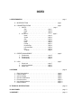
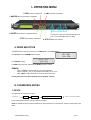
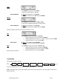
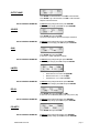
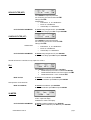
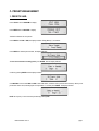
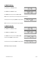
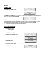
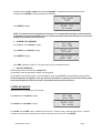
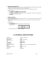
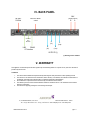
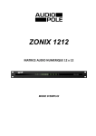
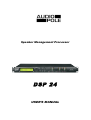
Speaker Management Processor DSP 24 USER’S MANUAL Safety Instructions READ CAREFULLY THE FOLLOWING INSTRUCTIONS This symbol indicates the presence of a dangerous voltage. This made symbol refers to information in the instructions manual. POWER SUPPLY Connect the appliance only on a current corresponding to the characteristics listed in the back of the device. Failure to observe this precaution could result in fire or electric shock, or a failure not covered by the warranty. POWER CORD Before using the appliance for the first time, check that the supply voltage is consistent with that of the sector. Before connection to the mains check that the power cord is properly plugged. Route the power cord so that it cannot be squashed or bent and keep it away from moisture and significant heat sources. In case of deterioration or failure please contact dealer to replace it with an identical cord. A damaged cord may result in fire or electric shock. PROTECTIVE GROUND The appliance must be connected to the ground, don't remove the ground wiring of the power cord connector. HUMIDITY Do not expose the unit to rain or moisture and do not place container containing a liquid that might tip over. Do not handle any connector with wet hands. In case of thunderstorm, turn the unit off and disconnect it from any power outlet. HEAT Do not install the unit in a place subject to excessive heat or direct radiation from the Sun. Operating ambient temperature must not be below 5 ° C (41 ° F) or above 35 ° C (95 ° F). DAMAGE Unplug immediately in the event of introduction of liquids or objects in the device as well as in the event of damage to the power cable. Also unplug the unit if it emits smoke, an odor, or unusual noise. Then contact a dealer or a Service Center authorized by Audiopole. DISPOSAL This symbol indicates that the disposal of this product is submitted to local regulations. Please contact your local dealer. INDEX I- OPERATING MENU . . . . . . . . . . . . . . . . . . . . . . . . . . . . . . . . . . . . . . . . . . . . . . . . . . . . . . . . . . page 1 A- MODE SELECTION . . . . . . . . . . . . . . . . . . . . . . . . . . . . . . . . . . . . . . . . . . . page 1 B- PARAMETERS EDITING . . . . . . . . . . . . . . . . . . . . . . . . . . . . . . . . . . . . . . page 1 1- INPUTS . . . . . . . . . . . . . . . . . . . . . . . . . . . . . . . . . . . . . . . page 1 Gain . . . . . . . . . . . . . . . . . . . . . . . . . . . . . page 1 Delay . . . . . . . . . . . . . . . . . . . . . . . . . . . . page 2 EQ . . . . . . . . . . . . . . . . . . . . . . . . . . . . . . page 2 2- OUTPUTS . . . . . . . . . . . . . . . . . . . . . . . . . . . . . . . . . . . . . page 2 Name . . . . . . . . . . . . . . . . . . . . . . . . . . . . . . page 2 Source . . . . . . . . . . . . . . . . . . . . . . . . . . . . . page 3 Gain . . . . . . . . . . . . . . . . . . . . . . . . . . . . . . . page 3 Limiter . . . . . . . . . . . . . . . . . . . . . . . . . . . . . page 3 Delay . . . . . . . . . . . . . . . . . . . . . . . . . . . . . . page 3 Polarity . . . . . . . . . . . . . . . . . . . . . . . . . . . . page 3 Hi-pass Filter . . . . . . . . . . . . . . . . . . . . . . . . page 4 Low-pass Filter . . . . . . . . . . . . . . . . . . . . . . page 4 EQ . . . . . . . . . . . . . . . . . . . . . . . . . . . . . . . page 4 VU Meter . . . . . . . . . . . . . . . . . . . . . . . . . . page 4 C- PRESETS MANAGEMENT. . . . . . . . . . . . . . . . . . . . . . . . . . . . . . . . . . . . . . page 5 1- Presets save . . . . . . . . . . . . . . . . . . . . . . . . . . . page 5 2- Presets recall . . . . . . . . . . . . . . . . . . . . . . . . . . . page 6 3- Presets delete . . . . . . . . . . . . . . . . . . . . . . . . . . page 6 D- LOCK . . . . . . . . . . . . . . . . . . . . . . . . . . . . . . . . . . . . . . . . . . . . . . . . . . . . . . page 7 1- Simple lock . . . . . . . . . . . . . . . . . . . . . . . . . . . . . page 7 2- Lock with password . . . . . . . . . . . . . . . . . . . . . . page 7 3- Display lock . . . . . . . . . . . . . . . . . . . . . . . . . . . page 8 II- APPENDIX 1234567- . . . . . . . . . . . . . . . . . . . . . . . . . . . . . . . . . . . . . . . . . . . . . . . . . . . . . . . . . . . . . . . page 9 Digital input selection . . . . . . . . . . . . . . . . . . . . . . . . . . . . . . . . . . . . . . . . . Power-on status . . . . . . . . . . . . . . . . . . . . . . . . . . . . . . . . . . . . . . . . . . . . . Unit for the delay . . . . . . . . . . . . . . . . . . . . . . . . . . . . . . . . . . . . . . . . . . . . . Real time modifications . . . . . . . . . . . . . . . . . . . . . . . . . . . . . . . . . . . . . . . . Firmware version . . . . . . . . . . . . . . . . . . . . . . . . . . . . . . . . . . . . . . . . . . . . . User interface selection . . . . . . . . . . . . . . . . . . . . . . . . . . . . . . . . . . . . . . . . Reset procedure . . . . . . . . . . . . . . . . . . . . . . . . . . . . . . . . . . . . . . . . . . . . . page 9 page 9 page 9 page 9 page 10 page 10 page 10 III- TECHNICAL SPECIFICATIONS . . . . . . . . . . . . . . . . . . . . . . . . . . . . . . . . . . . . . . . . . . . . . . . . page 10 IV- BACK PANEL . . . . . . . . . . . . . . . . . . . . . . . . . . . . . . . . . . . . . . . . . . . . . . . . . . . . . . . . . . . . . . page 11 V- WARRANTY . . . . . . . . . . . . . . . . . . . . . . . . . . . . . . . . . . . . . . . . . . . . . . . . . . . . . . . . . . . . . . . page 11 I- OPERATING MENU 2- PM2 Parameter 2 adjustment 3- PM3 Parameter 3 adjustment 1- NAV/PM1 Browse & Parameter 1 adjustment 4- ENTER Menu selection or parameter setting 5- ESC Cancel function or Backward 7- Quick push: selection for parameter Edit (blue Led) Push > 2 sec: Mute/unMute (red Led = Mute) 6- UTILITY Utility menu selection A- MODE SELECTION The DSP24 has two factory pre-set modes: “1 x 2 Ways Xover’’ and “4 Ways Xover’’. Press UTILITY and use NAV/PM1 button to display: Press ENTER to display: Use PM2 to select the menu, and then press ENTER two times to confirm. REMARK: • • Mode “1 x 2 Ways” assigns the inputs to the outputs like below : Input A to Outputs 1 (Low) / 2 (Hi), and Input B to Outputs 3 (Low) / 4 (Hi) Mode “4 Ways” assigns the Input A to all outputs. Input B is not used. Routing and filters can be edited afterwards (see paragraph B - 2 below). B- PARAMETERS EDITING 1- INPUTS: The signal path for every input is as follow: Input A or B GAIN DELAY 5 bands EQ To filter and output assignment Press (quick push) the button 7 of the input, the blue Led lights. NOTE: It is possible to adjust two inputs simultaneously: press the button 7 of one other input. The first one has priority on the others. UWER’S MANUAL DSP 24 page 1 GAIN: Press ENTER then adjust the value with PM2 It varies from -12dB to +6dB by 0.1dB steps. NEXT PARAMETER: A- without gain modification: press NAV/PM1 B- after a gain modification: press ESC then press NAV/PM1 DELAY : Press ENTER then adjust the values with PM2 and PM3 It varies from 0m to 288.659m (848ms) by 7cm steps (0,02ms). NEXT PARAMETER: A- without delay modification: press NAV/PM1 B- after a delay modification: press ESC then press NAV/PM1 The DSP 24 features 5 bands EQ on every input, named EQ-1 to EQ-5 EQ-1: Press ENTER then adjust the parameters: (idem EQ-5) • Variable frequency from 20Hz to 20,000Hz with NAV/PM1 • Variable bandwidth with Low Shelve -6 or -12dB, or 0.05 and 3.0 Octave with PM2 • Variable level between -15 and -15dB with PM3 MOVE TO EQ-2: A- without EQ-1 modification: press NAV/PM1 B- after EQ-1 modification: press ESC then press NAV/PM1 EQ-2 : Same procedure for each band. Press ENTER then adjust the parameters: (idem EQ-3 & 4) • Variable frequency from 20Hz to 20,000Hz with NAV/PM1 • Variable bandwidth between 0.05 and 3.0 Octave with PM2 • Variable level between -15 and -15dB with PM3 2- OUTPUTS: The signal path for outputs is as follow: Input selection GAIN DELAY Hi-‐pass Filter Low-‐pass Filter 7 B ands EQ Polarity Limiter Output Press (quick push) the button 7 of the selected output, the blue Led lights. NOTE: It is possible to adjust several outputs simultaneously: in this case press the button 7 of one other outputs. The first one has priority on the others. UWER’S MANUAL DSP 24 page 2 OUTPUT NAME: Press ENTER, the first letter blinks. Use PM2 to select the letter Press ENTER to go to the next letter. Use PM2 to select the letter Repeat to write the full name GO TO THE NEXT PARAMETER: A- without having changed the name: press NAV/PM1 B- after the name change: press ESC and press NAV/PM1 SOURCE : Press ENTER then adjust with PM2 The source can be input A, input B or both inputs summation. GO TO THE NEXT PARAMETER: A- without having changed the source: press NAV/PM1 B- after the source change: press ESC and press NAV/PM1 GAIN: Press ENTER then adjust with PM2 It varies from -12dBto +6dB with 0.1dB step GO TO THE NEXT PARAMETER: A- without having changed the gain: press NAV/PM1 B- after the gain change: press ESC and press NAV/PM1 LIMITER: Press ENTER then adjust the parameters: • Attack time from 5 to 200ms with NAV/PM1 • Release time from 0.1 to 3s with PM2 • Threshold from -10 to +20dB with PM3 GO TO THE NEXT PARAMETER: A- without having changed the limiter: press NAV/PM1 B- after the limiter change: press ESC and press NAV/PM1 DELAY: Press ENTER then adjust with PM2 and PM3 It varies from 0m to 288.659m (848ms) with 7cm (0.02ms) step GO TO THE NEXT PARAMETER: A- without having changed the delay: press NAV/PM1 B- after the delay change: press ESC and press NAV/PM1 POLARITY: Press ENTER then adjust with PM2 GO TO THE NEXT PARAMETER: USER’S MANUAL DSP 24 A- without having changed the polarity: press NAV/PM1 B- after the polarity change: press ESC and press NAV/PM1 page 3 HI-PASS FILTER (HPF): Press ENTER then adjust the parameters Cut off frequency from 20Hz to 20kHz with PM2 Filter type with PM3 Available filters: • Butterworth 6, 12, 18 or 24dB/Octave • Bessel 12 or 24dB/Octave • Linkwitz-Riley 12 or 24dB/Octave GO TO THE NEXT PARAMETER: A- without having changed the HPF: press NAV/PM1 B- after the HPF change: press ESC and press NAV/PM1 LOW-PASS FILTER (LPF) Press ENTER then adjust the parameters Cut off frequency from 20 Hz to 20 kHz with PM2 Filter type with PM3 Available filters: • • • GO TO THE NEXT PARAMETER: Butterworth 6, 12, 18 or 24dB/Octave Bessel 12 or 24dB/Octave Linkwitz-Riley 12 or 24dB/Octave A- without having changed the LPF: press NAV/PM1 B- after the LPF change: press ESC and press NAV/PM1 The DSP 24 features a 7 band EQ on every output: EQ-1 to EQ-7. EQ-1: Press ENTER then adjust the parameters: (idem EQ-5) § Variable frequency from 20Hz to 20,000Hz with NAV/PM1 § Variable bandwidth between 0.05 and 3.0 Octave with PM2 § Variable level between -15 and -15dB with PM3 MOVE TO EQ-2: A- without EQ-1 modification: press NAV/PM1 B- after EQ-1 modification: press ESC then press NAV/PM1 Same procedure for the others EQ. MOVE TO OTHER EQ: A- without EQ modification: press NAV/PM1 B- after EQ modification: press ESC then press NAV/PM1 VU-METER : Press ENTER then adjust with PM2 LEVEL: output level display LIMITER ACT: Limiter action display GO TO THE NEXT PARAMETER: A- without VU-Meter modification: press NAV/PM1 B- after VU-Meter modification: press ESC then press NAV/PM1 USER’S MANUAL DSP 24 page 4 C- PRESETS MANAGEMENT 1- PRESETS SAVE: Press UTILITY and use NAV/PM1 to display: Press ENTER and use NAV/PM1 to display: The DSP 24 features 24 user presets Press ENTER: use PM2 or PM3, the display indicates “Empty Memory", for instance : Press ENTER to valid the preset number, the display indicates: To clear and overwrite an existing preset, press ENTER, then the display indicates: Confirm by pressing ENTER and the display indicates: Use NAV/PM1 to browse and PM2 and PM3 to select the letters, create the name (16 characters maximum). All the preset parameters will be saved, including input and output Mute. To confirm press ENTER. The display indicates: NOTE: At any time you can cancel the procedure by pressing ESC. USER’S MANUAL DSP 24 page 5 2- PRESETS RECALL: Press UTILITY and use NAV/PM1 to display: Press ENTER and use NAV/PM1 to display: Press ENTER and browse the preset list with PM2 and PM3 NOTE: If there is no preset already saved, the display indicates «No Stored XOvers » Confirm the preset choice by pressing ENTER, the display indicates: NOTE: At any time you can cancel the procedure by pressing ESC. 3- PRESETS DELETE: Press ENTER and use NAV/PM1 to display: Press ENTER and use NAV/PM1 to display: Press ENTER and browse the preset list with PM2 and PM3. Confirm by pressing ENTER, the display indicates: Confirm the preset choice by pressing ENTER, the display indicates: NOTE: Delete a Preset is irreversible. USER’S MANUAL DSP 24 page 6 D- LOCK 1- SIMPLE LOCK Press UTILITY and use NAV/PM1 to display: Press ENTER and use NAV/PM1 pour to display: Press ENTER, then press PM2, select « On » to lock, or « Off » to unlock the device. The current status is indicated by the asterisk in the right corner of the screen. Confirm with ENTER. NOTES: a. When the device is locked, none of the parameters can be modified. If this procedure is known by the user, the parameters can be easily changed. In case of fixed installation or for renting business the procedure could be not applicable: in this case see the procedure described in paragraph D2. b. It is possible to have all the parameters invisible: see chapter D3. 2- LOCK WITH PASSWORD This procedure has 3 steps: a. Create a password b. Confirm the password c. Lock the device a. CRERATE A PASSWORD Press UTILITY and use NAV/PM1 to display: Press ENTER and use NAV/PM1 to display: Press ENTER to display: The factory password is « 000000 ». Select the data with PM2 and PM3 and browse with NAV/PM1. Press ENTER to display: New Password [ ] USER’S MANUAL DSP 24 page 7 Select the data with PM2 and PM3 and browse with NAV/PM1. The password cannot exceed more than 6 characters. Press ENTER to display (example with «DPA240»): Press ENTER to display: NOTE: To unlock the devise the password is necessary. It is recommended not to forget it, and to memorize it somewhere. In case this password is lost, it is necessary to make a total reset of the device. In this case all settings and parameters will be lost forever. b. CONFIRM THE PASSWORD Press UTILITY and use NAV/PM1 to display: Press ENTER and use NAV/PM1 to display: Press ENTER to display: Press PM2, and select « Enable ». This option works only if the password is known. c. UNLOCK THE DEVICE Follow the instructions as described on Simple Lock. It is possible to make all parameters invisibles: see paragraph 3. At this stage the device is fully locked: none of the button is active, except UTILITY, which enables the password input. In case the password is forgotten or lost, only a full reset of the device is possible. The reset is the factory status when purchasing the device for the first time: all parameters and presets are lost forever. 3- DISPLAY UNLOCK Whatever the choices, the parameters can be invisible. Press UTILITY and use NAV/PM1 to display: Press ENTER and use NAV/PM1 to display: Press ENTER, then with PM2, select « Parameter will not be shown » for display locking, « Parameter will be shown » for display unlocking. The current status is indicated with an asterisk on the right corner of the screen. Press ENTER. USER’S MANUAL DSP 24 page 8 II- APPENDIX 1- DIGITAL INPUT SELECTION The DPS 24 has a SP-DIF (RCA) digital input but it cannot operate with analog and digital inputs simultaneously. The input format needs to be specified before any operation. Selection of the digital input: • Press UTILITY and use NAV/PM1 to display «System Utilities» • Press ENTER and use NAV/PM1 to display «Input Routing». The current status is indicated with an asterisk on the right corner of the screen. • Press ENTER and use PM2 or PM3 to select «Digital». • Press ENTER 2- POWER-ON STATUS When the main power in switched on, the option “Fade-In: On” set the output level gradually up to the previous value of the last switch off. If the option “Fader-In: Off” is selected, the output level is set to its nominal value instantaneously. Selection of the Power-On status: • Press UTILITY and use NAV/PM1 to display «System Utilities» • Press ENTER and use NAV/PM1 to display «Power-On Procedure» • Press ENTER and use PM2 or PM3 to select «Fade-In: On» or «Fade-In : Off». The current status is indicated with an asterisk on the right corner of the screen. • Press ENTER 3- UNIT FOR THE DELAY The delay adjustment can be specified in Distance (meters) or in Time (milliseconds) Selection of the unit: • Press UTILITY and use NAV/PM1 to display «System Utilities» • Press ENTER and use NAV/PM1 to display «Delay Units» • Press ENTER and use PM2 or PM3 to select «Distance (m) » o «Time (ms) ». The current status is indicated with an asterisk on the right corner of the screen. • Press ENTER 4- REAL TIME MODIFICATIONS When parameters are modified some artifacts may occur. The DSP24 can attenuate the level during the parameters modification. Selection of an automatic attenuation: • Press UTILITY and use NAV/PM1 to display «System Utilities» • Press ENTER and use NAV/PM1 to display «Ramps on Change» • Press ENTER and use PM2 or PM3 to select «Ramps: On» for an automatic attenuation, or « Ramps: Off». The current status is indicated with an asterisk on the right corner of the screen. • Press ENTER 5- FIRMWARE VERSION To know the Firmware version of the device: • Press UTILITY and use NAV/PM1 to display «System Utilities» • Press ENTER and use NAV/PM1 to display «Software Version». • Press ENTER: the firmware version is displayed. • Press ESC to escape this function display. USER’S MANUAL DSP 24 page 9 6- USER INTERFACE SELECTION The DSP 24 can be programmed by a computer. There is an USB port (cable supplied) and a RS485 port (XLR). The USB port enables the connection between one PC computer and one single DSP24. The RS485 enables the communication between one PC computer and a network including several DSP24. Selection of the interface: • Press UTILITY and use NAV/PM1 to display «System Utilities» • Press ENTER and use NAV/PM1 to display «Interface Setup» • Press ENTER and use PM2 or PM3 to select «Source: USB» or «Source: RS485. The current status is indicated with an asterisk on the right corner of the screen. • Press ENTER 7- RESET PROCEDURE If the DSP 24 has been locked with a password and the password is lost or forgotten the device cannot be unlocked with the programmed parameters anymore. The device needs to be reset to the factory parameters status. In this case all parameters and presets will be definitively deleted and lost. Reset of the device: • Switch off the DSP 24. • Press ENTER, ESC and UTILITY simultaneously by switching the power on. • The display indicates : • Release the button and wait for the end of the procedure. III- TECHNICAL SPECIFICATIONS Analog inputs: Maximum input level: Analog outputs: Maximum output level: DSP: A/D converters: D/A converters: Sampling frequency: Stereo digital input S-PDIF: S/N ratio: THD + N: Frequency response (bypass): Power supply: Interface: USER’S MANUAL DSP 24 channel A, B, balanced XLR +20 dBu channel 1-4, balanced XLR +20 dBu SAM3716, 24 bits AKM5392, 24 bits AKM4396, 24 bits 48k Hz compatible with 32 kHz, 44.1 kHz and 48 kHz sampling rate 110 dBA 0.005% 20 Hz-20 kHz (+/-1dB) Switching USB - RS485 page 10 IV- BACK PANEL MIX (Analog outputs) DIGITAL INPUT 90-240V 50/60Hz B S-PDIF Cascade to other DSP24/26 USB RS485 PC Interface A (Hi) B (Hi) A A (Low) B (Low) OUTPUTS (*) (*): Routing can be modified V- WARRANTY This appliance is warranted parts and labor against any manufacturing defects for a period of two years from the date of purchase by the first user. Conditions 1. 2. 3. 4. 5. The unit has been installed and implemented by observing the safety instructions in this operating manual. The device was not diverted from its destination, either voluntary or accidental, and suffered no deterioration or modification other than those described here or explicitly authorized by AUDIOPOLE. All modifications or repairs have been carried out by an authorized service station. The defective product must be returned with the dealer who made the sale or to an authorized service station with proof of purchase. The device was properly packaged to avoid damage in transport. 22, rue Édouard Buffard, Z.A.C. de la Charbonnière, Montévrain - 77771 Marne-la-Vallée Cedex 4 - France Tél : + 33 (0)1 60 54 32 00 - Fax : + 33 (0) 1 60 54 31 90 - www.audiopole-pa.com - www.audiopole.fr USER’S MANUAL DSP 24 page 11