1
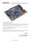
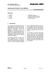
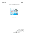
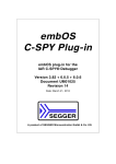
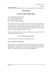
International Journal of Control and Automation
Vol. 8, No. 2 (2015), pp. 281-290
http://dx.doi.org/10.14257/ijca.2015.8.2.27
The Research of Light UAV Management Computer System
Li-qun Li and Hui Zhao
Aviation engineering institute, Civil Aviation Flight University of China
Sichuan Guanghan618307
[email protected]
Abstract
This paper compiles system integrated control program based on MSP430F169 flight
management computer design and production. There is interface circuit connecting with
peripheral system in the flight management computer design. We implement the hardware
connection of flight management computer with communication system, guided system,
flight control system and power system by the interface circuit, by which realizes the
both-way communication and autonomous flight of light UAV.
Keywords: Flight management computer, System integration, Interfacing, Data
transmission
1.Introduction
Unmanned Aerial Vehicle (UAV) is a kind of driven by power, machine, reusable
aircraft, Compared with manned aircraft, it has advantages of small volume, low cost,
convenient to use. Unmanned Aerial Vehicle is mainly composed of ground control
station and aircraft system, the ground control station including remote control handle, the
power supply, the plane management computer, monitor, wireless transceiver
module; Aircraft systems including aircraft body, power supply, the plane management
computer, flight control, wireless transceiver module and navigation. The ground control
station through wireless data transceiver module to send aircraft flight control, aircraft
control according to the received data control aircraft rudder surface deflection control of
the plane. Flight management computer is the core of the control system in the whole
UAV (unmanned aerial vehicle). The proper functioning is very important for UAV
control system. Flight management computer is the bridge of connecting every subsystem,
by which it can be easy to realize the control of every subsystem [1-3]. This paper
completed the system integration of hardware - based on MSP430F169 flight
management computer and write to design and manufacture of systems integration control
program. On the flight management computer designed for connected to the peripheral
interface circuit. Through the computer and communication interface circuit to realize the
plane management system, navigation system, flight control system, hardware
interconnected power system. If there is breakdown in the system, we cannot implement
data exchange of every system to cause that the whole UAV cannot be proper functioning.
Thus, we should reduce the faulted probability to the greatest extent [4-5].
Flight management computer can make wireless both-way communication to do the
transmission of control data, navigation data and other data. It offers technical support of
follow-up autonomous flight. 433 MHZ wireless communication module, can at the same
time for 50 users to work simultaneously on the same occasion, without the user manual
channel coordination and configuration. Receiving unit and the remote control unit has a
key for code automatically function, can realize the two-way communication, digital
address coding, large capacity, avoid address duplication, high sensitivity and strong
anti-jamming capability.
ISSN: 2005-4297 IJCA
Copyright ⓒ 2015 SERSC
International Journal of Control and Automation
Vol. 8, No. 2 (2015)
2.Designing Scheme of Flight Management Computer
The designing scheme includes two aspects. The one is main control chip. The other
one is interface design.
The designing of flight management computer MCU selects multifunction
ultra-low-power mixed signal to handle MSP430F169.
System integration establishes the physics connection between flight management
computer and each system by interface circuit. For satisfying the need of system
integration, we select UART for the communication interface of GPS model. UART
interface is a kind of serial asynchronous communication. The transmit data rate is very
slow. But the hardware requirement is low, and it is very easy to use. The hardware
connections only need TXD, RXD and GND three lines [2].
UAV system integrates communication system, flight control system, guided system
and other relevant system. For the normal running of every system control in flight
management computer, every system control needs to assign MCU resource by time
series. As shown in Figure 1, the sequential control diagram of system integration of
unmanned aerial vehicle (UAV)
Figure 1. Sequential Control Diagram of System Integration
3. Hardware Design of Flight Management Computer
The flight management computer adoptive MCU is MSP430F169. As shown in Figure
2, Flight management computer hardware block diagram.
282
Copyright ⓒ 2015 SERSC
International Journal of Control and Automation
Vol. 8, No. 2 (2015)
Figure 2. Flight Management Computer Hardware Block Diagram
The least system of MSP430F169 is the core of flight management computer. It
includes the following parts, like MSP430F169 single chip, reset circuit, periphery clock
circuit, JTAC simulated interface and BSL program download interface circuit. The
MSP430F169 schematic diagram is like the Figure 3.
Figure 3. MCU Least System
Copyright ⓒ 2015 SERSC
283
International Journal of Control and Automation
Vol. 8, No. 2 (2015)
3.1 Interface Circuit Design of Flight Management Computer
The design of peripheral interface circuit is to realize the communication connection
between MCU and peripheral model. It includes the following models’ interface circuit,
like SPI interface circuit communicated with RFC1101A model, UART interface circuit
communicated with GPS model, IIC interface circuit communicated with ultrasonic
model, four ways AD and PWM output interface and connected LCD and expansion
interface circuits[7].
RFC1101A interface circuit is the bridge of establishing communication between
RFC1101A wireless transmission model and MCU. Interface circuit is composed of SPI
communication interface and RFC1101A control interface. The RFC1101A interface
diagram’s like the Figure 4.
Figure 4. RFC1101A Interface Diagram
The communication between ultrasonic sounding model and MCU is implemented by
IIC. Convenient I2C port is very easy to connect the wire. It only need connect VCC,
GND, SDA and SCL four wires. High ultrasonic module interface circuit’s like the Figure
5.
Figure 5. High Ultrasonic Module Interface Circuit
GPS model has abundant interface. The interface circuit design in flight management
computer is the simplified design, which selects UART for reducing the complexity. GPS
module interface is like the Figure 6.
284
Copyright ⓒ 2015 SERSC
International Journal of Control and Automation
Vol. 8, No. 2 (2015)
Figure 6. GPS Module Interface
This system adopts MSP430F169 AD model. The function of AD interface circuit in
the ground is to collect voltage control signal from remote control handle input to finish
control signal gathering. AD in the plane has been gathered by aircraft battery electronic
detection input. Remote control and steering gear control input is like the Figure 7.
Figure 7. Remote Control and Steering Gear Control Input
LCD junction circuit selects LCD12864 as display. It is a raster graphics liquid crystal
display model, which has multiple interface means like four bits/ eight bits parallel, two
or three wires serial. The display resolution is 128*64, in which has 8192 Chinese
characters with the size of 16*16 and 128 ASCII character set with the size of 16*8. The
flexible interface means and easy operational order can constitute friendly all Chinese
man-machine interaction graphical interfaces. It not only can display 8*4 rows Chinese
characters with 16*16 dot matrix, but also can finish graphical display. Low voltage and
power dissipation is another outstanding feature. Compared with the same type graphical
dot matrix LCD, the model constituted LCD is much more concise on hardware circuit
configuration and display routine, and the price is just lower than the same dot matrix
LCD. The interface circuit of LCD12864 is composed by five control lines, eight data
lines and power line.
Copyright ⓒ 2015 SERSC
285
International Journal of Control and Automation
Vol. 8, No. 2 (2015)
4.Software Design of Flight Management Computer
MSP430F169 uses IAR Embedded Workbench EW430, which referred to as EW430 to
program. EW430 not only supports 430’s online simulation, but also can generate
executable file for BSL burn.
4.1MSP430 Development Environment
Preferable development environment is the essential for designing an integrated
single chip system. EW430 is programming software with high office efficiency,
which not only supports 430’s online simulation, but also can generate executable
file for BSL burn. The development tool has JTAG and BSL programming unit. For
reducing the developing cost, we use BSL programming unit [8].
4.2 Integrated Program Flow Chart of UAV
UAV is composed by ground station and aircraft system. UAV programming is divided
into two parts, like ground station programming and aircraft system programming
according to the system constitution. The two parts has similarity in constituting
framework. On the one hand, they both are compiled by modularized programming
thinking. On the other hand, they both have wireless transmission programming block.
And two programming both need to handle navigation data. The difference between them
is that ground data is the display, but aircraft data is to resolve data for user.
There are two major functions about ground station. The one is to generate control
signal and transmit it. The other one is to receive the signal and display navigation data
and battery electric quantity message from aircraft. The programming involves AD
transition, RFC1101A transmit-receive and inter conversion and LCD display.
Aircraft system has a few functions. The one is to receive control signal from ground
and generate relevant PWM control wave. The other one is to get navigation data with
periphery model and send packaged data back to the ground. The programming includes
AD transition, RFC1101A transmit-receive, UART communication and navigation data
analysis with GPS model and ultrasonic sounding IIC communication [9].
BSL burn software user interface of UAV system is concise and easy to use. We only
need to add IAR programming software to generate executable file. And then we choose
serial port and single chip type correctly to complete burn preparation. Finally, we can
click the executable to start procedure burn.
5. Debugging
Main purpose of the system debugging is to verify communication condition between
every subsystem and flight management computer and inspect whether each model runs
well [10].
5.1 Communication System Debugging
Communication system is composed by RFC1101A wireless transmission model.
Since it has no relevant simulated model in Proteus and CAD software, it cannot be
emulated and debugged on PC. The debugging is to measure relevant pin bottom output
waveform for working condition.
Flight management computer transceivers SI oscillogram in the ground station is like
Figure 8. The SO oscillogram in the aircraft station is like Figure 9.
286
Copyright ⓒ 2015 SERSC
International Journal of Control and Automation
Vol. 8, No. 2 (2015)
Figure 8. Ground Wireless Transmission SI Oscillogram
Figure 9. Aircraft Wireless Transmission SO Pin Transmission
After comparing the waveform of above two graphs, we can see that the waveform is
basic unanimous and wireless transmission model run well.
5.2 Navigation System Debugging
Navigation system is composed by GPS and ultrasonic sounding. GPS debugging can
be divided into PC debugging and flight management computer debugging.
Communication debugging between GPS model and PC is completed by serial
debugging assistant. Firstly, we connect PC and GPS model by USB line. And then we
open the serial debugging assistant on PC to set up serial. Baud rate is 9600. Check bit is
NONE. Data bit is 8. Stop bit is 1. Then, we open the power the GPS model.
When it receives data from GPS model, LED2 would fast blink. When it correctly
analyzes GPS navigation data, LED1 would blink.
Control system debugging. Control system debugging is waveform test of motor
control output and four channels steering gear control output. Electromechanical control
signal is PWM signal. After the test, we find that waveform got by receiving model and
transmitter model are the unanimous. After rotating relevant controller, positive pulsing
broadband of waveform would change. When potentiometer is in the different places, we
measure the waveform like Figure 10-12.
Copyright ⓒ 2015 SERSC
287
International Journal of Control and Automation
Vol. 8, No. 2 (2015)
Figure 10. Potentiometer is in the Neutral Position
Figure 11. Potentiometer is in the Leftmost End
Figure 12. Potentiometer is in the Rightmost End
6.Problems and Solution in Debugging
In the verifying flight initial stage, system integrated autonomous UAV system appears
serious electromagnetic interference problem. The problem is reflected between
RFC1101A antenna, GPS antenna and servo mechanism. The major result of disturb is
that engine body space is limited and adjustable of equipment layout is small. RFC1101A
requires arrangement core surrounding. Thus, battery cabin and ultrasonic probe is close
to RFC1101A. High frequency antenna should be far away from GPS antenna as far as
possible in principle. We adopt the following measure. We readjust equipment layout to
seek the optimum location of GPS antenna and high frequency antenna. And then we
forward lead GPS antenna and retrude microwave antenna.
288
Copyright ⓒ 2015 SERSC
International Journal of Control and Automation
Vol. 8, No. 2 (2015)
Reference
[1]. J. Wiley & Sons, “Unmanned Aircraft Systems –UAVS Design”, Development and Deployment Reg
Austin, (2010).
[2]. Q. Li, S. Zhang and J. Huang, “Single chip microcomputer and port theory”, Beijing: Electronic Industry
Press, Beijing, (2008).
[3]. L. Ben, J. Eric and V. George, “Augmenting UAV Autonomy”, IEEE Robotics Automation Magazine,
vol. 3, (2006), pp. 63-71.
[4]. D. Shim and H. Chung, “Autonomous Exploration in Unknown Urban Environment for Unmanned
Aerial Vehicles”, AIAA Guidance, Navigation and Control Conference, vol. 8, (2005), pp. 6381-6388.
[5]. K. Ahlstrom and J. Turin, “Future Architecture for flight control systems”, Proceedings of the 20th
Digital Avionics System Conference, vol. 10, no. 1, (2001), pp. 14-18, Beijing, china.
[6]. E. N. Wu, Q. A. Aydin, “Reliability-Based Modeling & Analysis of Fault Tolerant Flight Control
Systems, AIAA, (2005).
[7]. “Auto Pilot GCS Communication Protocol Manual”, UAV Flight Systems Inc., (2004).
[8]. “Texas Instruments Incorporated”, MSP430F16X datasheet, (2011).
[9]. Hayward, Campbell and Larkin, “Radio-frequency circuit design actual book”, M. Beijing: Posts and
Telecom Press, (2009).
[10]. “Ground Pilot Ground Control Station System Manual, UAV Flight Systems Inc., (2004).
Authors
Li Liqun, female, born in 1983, master degree, experimentalist.
The main research direction for aerospace electronics, electrical
automation.
E-mail:[email protected]
Unit's name and Address:Aviation engineering institute,Civil
Aviation Flight University of China, Sichuan Guanghan618307
Huizhao, female, born in 1970, master degree, engineer. The main research direction for
Aircraft maintenance
E-mail:[email protected]
Unit's name and Address:Mianyang Sub-College,Civil Aviation Flight University of
China, Sichuan Guanghan618307
Copyright ⓒ 2015 SERSC
289
International Journal of Control and Automation
Vol. 8, No. 2 (2015)
290
Copyright ⓒ 2015 SERSC