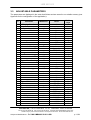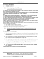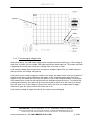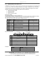
1
Hyper.X™ Reader
LMB6023-X2
Ex nA II T4
II 3G
User Manual
Ref: MU-LMB6023 X2-V1.0-GB
BALOGH SA
189, rue d’Aubervilliers - C.P. 97 75886 PARIS Cedex 18 – France ¡ Tel: 33 (0)1 44 65 65 00
¡ Fax: 33 (0)1 44 65 65 10 ¡ e-mail: [email protected] ¡ web: balogh-group.com
Limited Company with a Board of Directors and Capital of 800 000 € - RCS B Paris 582 061 073
LMB 6023-X2
CONTENT
1
PRESENTATION .......................................................................................... 5
2
DESCRIPTION.............................................................................................. 6
2.1
EXTERNAL DESCRIPTION ....................................................................................... 6
2.2
INTERNAL DESCRIPTION OF THE READER CASING ............................................ 8
3
CONFIGURATION OF THE READER ....................................................... 10
3.1
ACCESS TO THE CONTROL PANEL...................................................................... 10
3.2
USE OF THE CONTROL PANEL ............................................................................. 10
3.3
ADJUSTABLE PARAMETERS ................................................................................. 11
4
INSTALLATION .......................................................................................... 17
4.1
FIXING THE READER.............................................................................................. 17
4.2
POSITION OF THE READER................................................................................... 17
5
FUNCTIONING ........................................................................................... 18
5.1
POWER SUPPLY ..................................................................................................... 18
5.2
POWERING UP........................................................................................................ 20
5.3
READING THE TAGS .............................................................................................. 20
5.4
SEARCHING FOR DEFECTS .................................................................................. 21
APPENDIXES..................................................................................................... 22
APPENDIX 1: CE CERTIFICATION................................................................................... 22
APPENDIX 2: DIMENSIONS ............................................................................................. 23
APPENDIX 3: EXAMPLE OF CONFIGURATION OF THE SERIAL LINK ......................... 24
BALOGH SA, 189 rue d’Aubervilliers C.P. 97 75886 PARIS Cedex 18 FRANCE
Tel: 33 (0)1 44 65 65 00 Fax: 33 (0)1 44 65 65 10 Internet: http://www.balogh-group.com
Limited Company with a Board of Directors and Capital of 800 000 € - RCS B Paris 582 061 073
Subject to Modifications - Ref: MU-LMB6023 X2-V1.0-GB
p 2/24
LMB 6023-X2
PREFACE
Purpose of this manual
This manual presents the BALOGH LMB6023-X2 equipment.
It then indicates how to install it and how to use it.
The interfacing manual for the Hyper X (ref 13053/104) readers complete the information relating
to the interfaces given in this manual.
The Safety Instructions for the Hyper X LMB 6023-X2 (ref 13523/52) complete the information
relating to the installation given in this manual.
Reference of the manual
The manual’s generic reference is:
MU- <name of equipment> -II-L
in which:
MU denotes User Manual
II is the version number.
L is the language in which the manual is written
Update
Version
Date
no.
1.0
11/20/2008 Creation
Nature of the modification
Note
The information contained in the present manual may be modified without prior notice.
The company BALOGH cannot be held responsible for the consequences of any errors or
omissions, or for the erroneous interpretation of the information.
BALOGH SA, 189 rue d’Aubervilliers C.P. 97 75886 PARIS Cedex 18 FRANCE
Tel: 33 (0)1 44 65 65 00 Fax: 33 (0)1 44 65 65 10 Internet: http://www.balogh-group.com
Limited Company with a Board of Directors and Capital of 800 000 € - RCS B Paris 582 061 073
Subject to Modifications - Ref: MU-LMB6023 X2-V1.0-GB
p 3/24
LMB 6023-X2
BALOGH SA, 189 rue d’Aubervilliers C.P. 97 75886 PARIS Cedex 18 FRANCE
Tel: 33 (0)1 44 65 65 00 Fax: 33 (0)1 44 65 65 10 Internet: http://www.balogh-group.com
Limited Company with a Board of Directors and Capital of 800 000 € - RCS B Paris 582 061 073
Subject to Modifications - Ref: MU-LMB6023 X2-V1.0-GB
p 4/24
LMB 6023-X2
1 PRESENTATION
The LMB_6023-X2 reader is a standard monobloc reader integrated in a case adapted for ATEX
applications. It is presented in the form of a polycarbonate case with a compression gland cable
entry device.
LABELLING:
:
BALOGH SA, 189 rue d’Aubervilliers C.P. 97 75886 PARIS Cedex 18 FRANCE
Tel: 33 (0)1 44 65 65 00 Fax: 33 (0)1 44 65 65 10 Internet: http://www.balogh-group.com
Limited Company with a Board of Directors and Capital of 800 000 € - RCS B Paris 582 061 073
Subject to Modifications - Ref: MU-LMB6023 X2-V1.0-GB
p 5/24
LMB 6023-X2
2 DESCRIPTION
2.1
EXTERNAL DESCRIPTION
The LMB_6023-X2 is a monoblock reader consisting of an LMB_7023 reader inside a casing
adapted for ATEX applications.
The LMB_6023-X2 reader is a compact reader. It comes in the form of a ATEX certified
polycarbonate casing unit without halogen:
•
•
•
•
•
•
•
•
•
External dimensions: 278x378x130mm +/-1mm
Mounting dimensions: 254x354mm +/- 1mm – 4 holes of Ø7mm
Weight: 5.1Kg
Colour: Grey RAL 7035
Mechanical resistance: see manufacturer’s documentation (FIBOX ref. FEX 3828 13 G)
Protection IP66/67
Protection ATEX : Ex II 3G - Ex II nA T4 in accordance with standard EN 60079-15
Power supply: Between +12VDC and +24VDC, max. current 1.5A.
Operating temperature: -10°C / +50°C
BALOGH SA, 189 rue d’Aubervilliers C.P. 97 75886 PARIS Cedex 18 FRANCE
Tel: 33 (0)1 44 65 65 00 Fax: 33 (0)1 44 65 65 10 Internet: http://www.balogh-group.com
Limited Company with a Board of Directors and Capital of 800 000 € - RCS B Paris 582 061 073
Subject to Modifications - Ref: MU-LMB6023 X2-V1.0-GB
p 6/24
LMB 6023-X2
The LMB 6023-X2 casing is composed of
Cover
Casing base
Compression Gland
Manufacturer
FIBOX
FIBOX
FIBOX
Manufacturer's reference
FEX 3828-13G
PC-3828 + machining
SS 10256
The reader has an ATEX certified compression gland which can take a cable with a diameter of
between 5.5 mm and 10 mm. The cable is not supplied.
Compression Gland
detail
Four screws are available in the back plate of the casing for fixing the swivel support given.
BALOGH SA, 189 rue d’Aubervilliers C.P. 97 75886 PARIS Cedex 18 FRANCE
Tel: 33 (0)1 44 65 65 00 Fax: 33 (0)1 44 65 65 10 Internet: http://www.balogh-group.com
Limited Company with a Board of Directors and Capital of 800 000 € - RCS B Paris 582 061 073
Subject to Modifications - Ref: MU-LMB6023 X2-V1.0-GB
p 7/24
LMB 6023-X2
2.2
INTERNAL DESCRIPTION OF THE READER CASING
The LMB_6023-X2 reader consists of:
• A polycarbonate ATEX Certified casing ATEX without halogen with a base plate
• A standard reader base 13053, with an inter-antenna panel, type ASVA
• A standard AT2_2720 antenna assembled on 4 studs h=70 mm
• Two coaxial cables TNC fem / TNC male to link the antenna to the coaxial cables TNC
male of the inter-antenna panel
• A wiring duct 25x50x240 mm to hold the cables
Reader base 13053
4 studs
Wiring duct
Assembly screw AT2
AT2_2720
BALOGH SA, 189 rue d’Aubervilliers C.P. 97 75886 PARIS Cedex 18 FRANCE
Tel: 33 (0)1 44 65 65 00 Fax: 33 (0)1 44 65 65 10 Internet: http://www.balogh-group.com
Limited Company with a Board of Directors and Capital of 800 000 € - RCS B Paris 582 061 073
Subject to Modifications - Ref: MU-LMB6023 X2-V1.0-GB
p 8/24
LMB 6023-X2
Internal connection for the antenna
Antenna AT2_2720-ASVA
ANT IN
ANT OUT
TNC male jack
TNC female socket
Cables RG174
l=2m
TNC male jack
TNC fem socket
square plate
Inter-antenna plate
Reader base LMB 13053
User-machine interface of the reader base control panel
low-voltage
LED
DT06
JK01
1 2 3
2-colour LED
status of inputs/outputs
General status
DR03 DR04 DR05 DR06
DN02
reset
link TTL
JT01
JR04
1 2 3 4
Inputs
JR03
1 2 3 4 5 6
Outputs
link status
RS
link status
TTL
DR09
link RS
JR02
JR01
1 2 3 4 5
1 2 3 4 5
displays
UN17 - UN18
buzzer
The principal control features are
• a 2-colour led (DN02) indicating the status of the reader and the presence of one or more
tags,
• a buzzer that sounds when a tag is detected (if activated),
• a reset push button (black),
• a control panel consisting of two 7-segment displays (UN17-UN18) and two push buttons
BALOGH SA, 189 rue d’Aubervilliers C.P. 97 75886 PARIS Cedex 18 FRANCE
Tel: 33 (0)1 44 65 65 00 Fax: 33 (0)1 44 65 65 10 Internet: http://www.balogh-group.com
Limited Company with a Board of Directors and Capital of 800 000 € - RCS B Paris 582 061 073
Subject to Modifications - Ref: MU-LMB6023 X2-V1.0-GB
p 9/24
LMB 6023-X2
3 CONFIGURATION OF THE READER
ATTENTION: This operation requires opening of the case and must therefore not be performed in
a sensitive zone. Refer to the Safety Instructions for the Hyper X LMB 6023-X2 (ref 13523/52).
3.1
ACCESS TO THE CONTROL PANEL
Remove the cover of the casing to access the reader base and the antenna.
3.2
USE OF THE CONTROL PANEL
Role of the buttons
Red button
• select a parameter
• save the modified parameter
Black button
• displays the value of the selected parameter
• selects the value of the chosen parameter
To display the parameter you want, press the red button until the corresponding mnemonic is
displayed (cyclical display).
To display the value of this parameter, press the black button until the mnemonic displayed
corresponds to the desired value (cyclical display).
Press the red button again to save this value (during the save, "SA" is displayed for 1 second).
To sum up, starting from a given status and, depending on the button chosen, the effects are as
follows
status
display off
display mnemonic of parameter n
display value of parameter n
display value + “.”
ö
ø
ö
ø
ö
ø
ö
ø
press button
red
black
red
black
red
black
red
black
consequence
displays mnemonic of 1st parameter
nil
displays mnemonic parameter n+1
displays value parameter n
displays mnemonic parameter n+1
displays next value + “.”
displays “SA”, save
displays following value + “.”
Notes:
1. If you do not want to save a modified parameter
• wait until the 8 second time out is up
• OR press the Reset button
2. By default, the display units are read vertically, with the led underneath.
If the reader must be assembled with the led uppermost, the read direction can be inverted by
changing the first parameter. In this case, the black and red buttons retain their functions.
3. The display sequence of the black and red buttons is cyclical.
The successive parameters are obtained either by briefly pressing the button, or by keeping it
pressed down, which will make the parameters scroll down every 0.3 s.
4. To return to the default values (ex-factory) press simultaneously on the Reset button and the
Change button (black).
BALOGH SA, 189 rue d’Aubervilliers C.P. 97 75886 PARIS Cedex 18 FRANCE
Tel: 33 (0)1 44 65 65 00 Fax: 33 (0)1 44 65 65 10 Internet: http://www.balogh-group.com
Limited Company with a Board of Directors and Capital of 800 000 € - RCS B Paris 582 061 073
Subject to Modifications - Ref: MU-LMB6023 X2-V1.0-GB
p 10/24
LMB 6023-X2
3.3
ADJUSTABLE PARAMETERS
The parameters are displayed in the order that follows and are saved in non-volatile memory (see
Appendix for the configuration of the application):
n°
Parameter
Mnemonic
Value
Visible
value
1
Display direction
--
2
3
Channel number
Reread time
nC
tP
4
Buzzer
bu
5
Int code filtering
FI
6
Integrator code size
tC
7
Antenna read LED
LE
8
Type of functionning
tF
9
Function tags
bF
0
1
0 à 31
0,1 s
0,5 s
1s
2s
5s
10 s
OFF
ON
néant
1er code
EEPROM
3
4
normal
autre
0
1
2
3
OFF
uP
dn
0 à 31
0
1
2
3
4
5
oF
on
0
1
2
3
4
oF
on
0
1
2
3
oF
10
Journal
Jo
11
Type of RS interface
tA
12
Type of CO interface
tO
ON
aucun
1
2
3
RS 232
RS 422
RS 485
inutilisé
on
oF
1
2
3
23
42
48
nu
ISO2 fixe
ISO2 var
WIEGAND
1, 2, …,31
9 600
4 800
1 200
19 200
IF
Ir
IE
1 à 31
96
48
12
19
13
14
JBUS Addresse
Rate
Ad
br
BALOGH SA, 189 rue d’Aubervilliers C.P. 97 75886 PARIS Cedex 18 FRANCE
Tel: 33 (0)1 44 65 65 00 Fax: 33 (0)1 44 65 65 10 Internet: http://www.balogh-group.com
Limited Company with a Board of Directors and Capital of 800 000 € - RCS B Paris 582 061 073
Subject to Modifications - Ref: MU-LMB6023 X2-V1.0-GB
p 11/24
LMB 6023-X2
Visible
value
n°
Parameter
Mnemonic
Value
15
Character format
Fo
8 bits/without
parity
7 paired bits
7 unpaired bits
ASCII
code alone
Format_td
JBUS
Interrupt
Polling
0,1 s
0,2 s
0,5 s
1s
2s
1 to 4
not used
buzzer copy
2s read
host
green LED
not used
vehicle BF
pile badge basse
host
red LED
0 to 3
7P
7I
AS
CS
td
Jb
oF
on
0
1
2
3
4
1à4
oF
1
2
3
4
oF
1
2
3
4
0à3
inactive
read
inactive
opening
oF
on
oF
on
100 ms
150
200
300
400
500
800
1000
0
1
2
3
4
5
6
7
16
Frame type
Fr
17
Polling/Interr
Po
18
MTBM
tb
19
20
No of transmissions
Output 1
nE
S1
21
Output 2
S2
22
23
24
Range
Reserved
Entry 1
Pr
E1
25
Entry 2
E2
26
27
Reserved
Period of hops
PE
8n
BALOGH SA, 189 rue d’Aubervilliers C.P. 97 75886 PARIS Cedex 18 FRANCE
Tel: 33 (0)1 44 65 65 00 Fax: 33 (0)1 44 65 65 10 Internet: http://www.balogh-group.com
Limited Company with a Board of Directors and Capital of 800 000 € - RCS B Paris 582 061 073
Subject to Modifications - Ref: MU-LMB6023 X2-V1.0-GB
p 12/24
LMB 6023-X2
EXPLANATIONS
1. DISPLAY DIRECTION
Allows the reader to be installed facing up or down, for the LED under the display (choose "uP") or
above the display (choose "dn"). The buttons keep their functions.
2. CHANNEL
This is the operating channel. The channels / frequencies table of correspondence is given in the
interface manual.
The special case of channel 0 corresponds to the "frequency hopping"; the hop period is
determined by parameter 27.
3. REREAD TIME
This is the time during which the tag code stays in the internal memory after its last detection. It
corresponds to the minimum time during which the tag must not be detected so that it can be
detected again. During this period the reader regards the tag as present in the detection area.
4. BUZZER
Confirmation or inhibition of the generation of a brief buzz at each detection of a tag.
5. INTEGRATOR CODE FILTERING
For filtering the tag codes according to the integrator code.
The value 1 corresponds to the filtering that exists on the traditional readers, i.e. the first code read
after a reset of the reader becomes the reference code.
A value of 2 or more indicates filtering according to one or more codes memorised in the EEPROM
memory.
These codes must be loaded by JBUS command.
6. INTEGRATOR CODE SIZE
Don't change this parameter (always equal to 3).
7. ANTENNA READ LED
For defining the behaviour of the antenna LED.
A single value is defined, which corresponds to
event
detection of tag
tag battery dead
functioning OK
defective functioning
LED
off for 1 s
red for 0.3 s
flashing green 3 times per second
flashing red slowly
8. TYPE OF FUNCTIONING
Enables you to choose between
• mode 0 (message generated at each detection of a new tag),
• mode 2 (message generated at each detection of a tag),
• mode 3 (mode 0 plus disappearance message).
BALOGH SA, 189 rue d’Aubervilliers C.P. 97 75886 PARIS Cedex 18 FRANCE
Tel: 33 (0)1 44 65 65 00 Fax: 33 (0)1 44 65 65 10 Internet: http://www.balogh-group.com
Limited Company with a Board of Directors and Capital of 800 000 € - RCS B Paris 582 061 073
Subject to Modifications - Ref: MU-LMB6023 X2-V1.0-GB
p 13/24
LMB 6023-X2
Mode 1 is reserved for a special use.
9. FUNCTION TAGS
Permits the recognition of special tag codes with which the configuration of the reader is possible.
The presentation of such a tag before the antenna enables the remote configuration of certain
parameters of the reader. The function tag manages 7 to 8 parameters.
This function is available via the software version v1.1.3.
If this parameter is inhibited (=oF), all the function tags will be inhibited.
10. JOURNAL (HISTORY)
Permits the dating and timing of certain events. These saves can be read with JBUS commands or
with a function tag.
11. TYPE OF RS INTERFACE
For choosing the type of RS interface: 232, 422 or 485.
This interface can be used as a host interface or a maintenance interface. If used as a host
interface, choose "nu" (not used) for the OC interface (see next item).
12. TYPE OF OC INTERFACE
For defining one of the open collector interfaces in host interface.
If the host interface is the RS interface, choose "nu" (not used).
13. ADDRESS
For addressing readers connected in a network. For a single reader: do not modify.
14. RATE OF ASYNCHRONOUS SERIAL LINKS
For choosing the rate of the RS link according to the host.
15. CHARACTER FORMAT
In JBUS frame, leave in 8 bits/without parity.
In ASCII or Code Only, choose the format according to the host.
16. FRAME TYPE
For defining the message transmitted following a tag detection.
For example, for tag (0)(123)(CODE_BADGE)
In polling mode, choose JBUS
message = 01 03 0e 30 31 32 33 43 4f 44 45 5f 4b 4a 44 47 4e xx xx
In interruption mode, the choices are
JBUS:
message = 02 04 0e 30 31 32 33 43 4f 44 45 5f 4b 4a 44 47 4e xx xx
ASCII:
message = 1.0.123CODE_BADGE(CR)(LF)
Code only:
message = 123CODE_BADGE
17. POLLING
For choosing how a tag code is transmitted to the host interface.
Polling OFF (interruption mode), the detection of a new tag generates a message that is
immediately sent to the interface.
Polling ON, this message is sent only in response to the appropriate JBUS command. If the reader
does not receive the command before the disappearance of the tag, the message is lost.
18. MTBM
For defining the Minimum Time Between Maintenance between two transmissions on the open
collector link, whether messages for different tags or for repetitions of messages (see the next
parameter).
BALOGH SA, 189 rue d’Aubervilliers C.P. 97 75886 PARIS Cedex 18 FRANCE
Tel: 33 (0)1 44 65 65 00 Fax: 33 (0)1 44 65 65 10 Internet: http://www.balogh-group.com
Limited Company with a Board of Directors and Capital of 800 000 € - RCS B Paris 582 061 073
Subject to Modifications - Ref: MU-LMB6023 X2-V1.0-GB
p 14/24
LMB 6023-X2
19. NUMBER OF TRANSMISSIONS
In RS interface and interruption mode, this is the maximum number of transmissions of the same
message in absence of acknowledgement.
In open collector interface, if this parameter is more than 1, each code is issued twice. The time
between two transmissions is set by the previous parameter.
20. OUTPUT 1
Enables the definition of the behaviour of the output when a tag is detected.
The values are
value
unused
copy buzzer
read 2 s
host
green LED
display
oF
1
2
3
4
description
activation for 100 ms to read a new tag
activation for 2 s to read a new tag
managed uniquely by JBUS commands
copies the green led of the reader base
21. OUTPUT 2
Enables the definition of the behaviour of the output when a tag is detected.
The values are
value
unused
BF vehicle
tag battery low
host
red led
display
oF
1
2
3
4
description
activation in vehicle mode (see document on function tags)
activation if the tag battery is fading
managed uniquely by JBUS commands
copies the red led of the reader base
The blue led is connected to output 2: to activate it you must pick display 4. In this case, the blue
led will light up for a fault detection or flash when the device is powered up.
22. RANGE
Enables the user to choose between 4 range values, from 0 (minimum) to 3 (maximum).
This parameter acts on the detection threshold, while keeping the transmission power of its
nominal value.
23. RESERVED
Parameter not accessible to the user.
24. ENTRY 1
Enables the user to confirm the reading of the tags with an entry signal.
In this case, if the entry is active (6V< Vin < 25V), the reading of the tags takes place, otherwise it
does not.
25. ENTRY 2
To be defined
26. RESERVED
Parameter not accessible to the user.
BALOGH SA, 189 rue d’Aubervilliers C.P. 97 75886 PARIS Cedex 18 FRANCE
Tel: 33 (0)1 44 65 65 00 Fax: 33 (0)1 44 65 65 10 Internet: http://www.balogh-group.com
Limited Company with a Board of Directors and Capital of 800 000 € - RCS B Paris 582 061 073
Subject to Modifications - Ref: MU-LMB6023 X2-V1.0-GB
p 15/24
LMB 6023-X2
27. PERIOD OF HOPS
Determines the time between two frequency hops in the case of functioning in random frequency
hops (channel number = 0, see parameter 2).
28. READER TYPE
Identifies the model of the reader (read only).
An example of a typical configuration of the reader LMB_6023-F is given in Appendix 3.
BALOGH SA, 189 rue d’Aubervilliers C.P. 97 75886 PARIS Cedex 18 FRANCE
Tel: 33 (0)1 44 65 65 00 Fax: 33 (0)1 44 65 65 10 Internet: http://www.balogh-group.com
Limited Company with a Board of Directors and Capital of 800 000 € - RCS B Paris 582 061 073
Subject to Modifications - Ref: MU-LMB6023 X2-V1.0-GB
p 16/24
LMB 6023-X2
4 INSTALLATION
ATTENTION: Refer to the Safety Instructions for the Hyper X LMB 6023-X2 (ref 13523/52).
4.1
FIXING THE READER
Fasten the reader using the four screws available on the back metallic plate.
4.2
POSITION OF THE READER
The directivity of the antenna AT2 in the LMB 6023-X2 reader is not symmetrical 45°x90°.
So the position of the reader is important. (See diagram below)
x
y
90°
45°
y
x
LMB 6023 : 4m (12feet)
LMB 6023 : 4m (12feet)
BALOGH SA, 189 rue d’Aubervilliers C.P. 97 75886 PARIS Cedex 18 FRANCE
Tel: 33 (0)1 44 65 65 00 Fax: 33 (0)1 44 65 65 10 Internet: http://www.balogh-group.com
Limited Company with a Board of Directors and Capital of 800 000 € - RCS B Paris 582 061 073
Subject to Modifications - Ref: MU-LMB6023 X2-V1.0-GB
p 17/24
LMB 6023-X2
5 FUNCTIONING
5.1
POWER SUPPLY
5.1.1 Functioning voltage of the LMB reader
The reader can be supplied with power between 12 Vdc (consumption in stabilized 1 A max.) and
24 Vdc (consumption in stabilized 0.5 A max.).
For an optimal performance of the reader in terms of reading distance, it is recommended to have
a power supply the least noisy possible (ripple + noise <100mVcc).
N.B.:
The extreme limits of functioning are between 11 Vdc and 28 Vdc, so it is crucial not to go under
11 V nor over 28 V to prevent any malfunctioning or the destruction of the reader.
The value of the minimal voltage recommended for the correct functioning of the reader is 11.5Vdc.
Below this level, the reader can continue to function but with its performances no longer
guaranteed, functioning in failsoft mode (see functioning at voltage limits).
Inside the casing a "low voltage" LED (DT6, see §1.2 Description internal control panel) indicates
that the voltage supplied to the detector is about 10.5Vdc.
When low voltage is detected, the reader activates a time out of 20 or 30 seconds. When the time
out is up, the reader tries to restart:
• if the voltage is correct, it starts to function
• if the voltage is still low, it reactivates the time out, and so on
In addition, the reader is protected against polarity reversals.
5.1.2 Start-up of the reader (information relating to the internal functioning of the
reader)
The reader starts up in several stages
1- When it is powered up, there is a first inrush current (Ipointe1) corresponding to the load of
the condensers of the LMB reader. This inrush current is several amperes for a very short
time of 5 to 10ms.
2- After it is powered up, the reader observes for a period the voltage available. This period
lasts between 0.5s and 1s depending on the voltage input.
3- If the input voltage is acceptable, there is a second inrush current (Ipointe2), corresponding
to the 'real' start-up of the reader. This current is lower than 1.5A with 12Vdc for a time
under 100ms. If the voltage supplied to the reader is higher, this second current will be
weaker (e.g. lower than 1A with 18Vdc or lower than 0.7A with 24Vdc)
Comment: Ipointe2 current is 1Atyp with 12Vdc for 10 to 20 ms
4- Then the current of the reader stabilises (Istab) to a current lower than 1A with 12Vdc or
0.5A with 24Vdc.
Comment: typically, the functioning current is 0.6Atyp with 12Vdc.
BALOGH SA, 189 rue d’Aubervilliers C.P. 97 75886 PARIS Cedex 18 FRANCE
Tel: 33 (0)1 44 65 65 00 Fax: 33 (0)1 44 65 65 10 Internet: http://www.balogh-group.com
Limited Company with a Board of Directors and Capital of 800 000 € - RCS B Paris 582 061 073
Subject to Modifications - Ref: MU-LMB6023 X2-V1.0-GB
p 18/24
LMB 6023-X2
Ipointe 1
Ipointe 2
Istab
5.1.3 Functioning at voltage limits
When powered up, the LMB reader observes the voltage input before starting up. If this voltage is
lower than 10.5Vdc, the 'low voltage' LED lights up and the reader starts up. The reader may have
a degraded functioning until it receives a voltage input of at least 11.5Vdc.
If the reader's voltage input is lower than a minimum voltage of about 9.5V, the reader does not
start up and the 'low voltage' led lights up.
If the power source used to supply the reader is too weak, the reader inrush current may lead to a
lowering of the input voltage available to the reader; if this voltage becomes lower than Vmin
(approx. 9.5V) the reader will stop, which will lead to a rise in the voltage available, so the reader
may restart with an inrush current that will lower the available voltage and so on. To prevent this
pumping phenomenon, the reader will go into sleep mode for about 20 to 30s, and try to restart
when this time is up. If the voltage is correct at the end of this time, the reader starts up again,
otherwise it goes into sleep mode for 20 to 30s and so on.
If the reader's voltage is higher than 28Vdc, the reader may be damaged..
BALOGH SA, 189 rue d’Aubervilliers C.P. 97 75886 PARIS Cedex 18 FRANCE
Tel: 33 (0)1 44 65 65 00 Fax: 33 (0)1 44 65 65 10 Internet: http://www.balogh-group.com
Limited Company with a Board of Directors and Capital of 800 000 € - RCS B Paris 582 061 073
Subject to Modifications - Ref: MU-LMB6023 X2-V1.0-GB
p 19/24
LMB 6023-X2
5.2
POWERING UP
An auto-test is made with each power up or reset. This can be monitored on the antenna led and, if
the reader is opened, on the internal displays which display successively the mnemonic of each
test.
When the initialisation is completed, if the result of all the internal tests is correct, the displays
switch off. Hence, in the absence of breakdown, the following events can be observed
successively.
no.
1
2*
3
4
5
test
RAM of work
RAM Log p 0
RAM Log p 1
Checksum flash
principal led
steady red
steady red
steady red
steady red
flashing green at 2 Hz
display
P
P0
P1
PE
off
buzzer
on
off
off
off
off
duration
<1s
3s
4s
1s
ad infinitum
In fact, other tests take place but at less than 50 ms and with fugitive display. Only if the test seizes
up can the display be useful.
* If the ‘‘log’’ parameter (10) is confirmed, i.e. different from 0, test 2 (display = P0) does not take
place. In the production output, the log is confirmed by default, so at the second start-up test 2
does not take place.
The reader is equipped with an antenna with an autodiagnosis function. So an additional test is
made after the autotest and a brief beep indicates that the autodiagnosis is correct. (see also the
interfacing manual ref.13053/104).
5.3
READING THE TAGS
The detection of a tag provokes
• the activation of the buzzer (if confirmed),
• a record in the log (if confirmed),
• the lighting up of the leds of the reader base and of the external led as shown in the
following table
Event
detection of tag
tag battery low
functioning OK
Reader base LED
off for 1 s
red for 0.3 s
flashing green 2 times per second
Blue LED
/
/
/
BALOGH SA, 189 rue d’Aubervilliers C.P. 97 75886 PARIS Cedex 18 FRANCE
Tel: 33 (0)1 44 65 65 00 Fax: 33 (0)1 44 65 65 10 Internet: http://www.balogh-group.com
Limited Company with a Board of Directors and Capital of 800 000 € - RCS B Paris 582 061 073
Subject to Modifications - Ref: MU-LMB6023 X2-V1.0-GB
p 20/24
LMB 6023-X2
5.4
SEARCHING FOR DEFECTS
ATTENTION: This operation requires opening of the case and must therefore not be performed in
a sensitive zone. Refer to the Safety Instructions for the Hyper X LMB 6023-X2 (ref 13523/52).
If a defect that can lead to the breakdown of the reader is detected at a higher level via JBus
requests, a test of the functioning of the reader must be carried out.
• interrupt the power supply
• remove the reader
• remove the cover
• restore the power supply
Local error codes
The search for defects is made at a higher level.
Locally (inside the reader), a hexadecimal error code indicates which test has failed (one bit per
test). Depending on the type of error, the reader is or is not capable of functioning.
The table below shows all the tests and the related error bits
no. display
1
2
3
4
5
6
7
8
9
test
P
P0
P1
PE
EE
SC
Sn
rt
IS
bit(s) of the error code
external RAM (work part)
external RAM (Log page 0)
external RAM (Log page 1)
checksum Flash memory
EEPROM memory
Serial Communications Controller (SCC)
component serial number
component RTC (real time clock)
RS electric interface
2
2
2
1
3
4, 5
7
8
6
Byte of the error code
MSB
8
bit
1
2
3
4
5
6
7
8
First digit
MSB
7
8
7
MSB
8
description
error checksum memory
error external access RAM
error access EEPROM access
error bus SCC
error SCC
error interface RS
error access component serial number
error circuit RTC
Second digit
MSB
7
8
7
consequence
reader unavailable
reader unavailable
reader unavailable
reader unavailable
reader unavailable
reader unavailable
reader unavailable
no log time & date
Examples
display
04
18
40
meaning
error access EEPROM
error component SCC
error access component serial number
BALOGH SA, 189 rue d’Aubervilliers C.P. 97 75886 PARIS Cedex 18 FRANCE
Tel: 33 (0)1 44 65 65 00 Fax: 33 (0)1 44 65 65 10 Internet: http://www.balogh-group.com
Limited Company with a Board of Directors and Capital of 800 000 € - RCS B Paris 582 061 073
Subject to Modifications - Ref: MU-LMB6023 X2-V1.0-GB
p 21/24
LMB 6023-X2
APPENDIXES
APPENDIX 1: CE CERTIFICATION
DECLARATION OF CONFORMITY
BALOGH Toulouse
105 Avenue du Général Eisenhower
31023 TOULOUSE cedex 1
FRANCE
0682
The present declaration certifies that the LMB* device is in conformity with the essential
requirements of European Directive R&TTE 1999/5/EC designed to harmonise the legislations of
the Member States concerning the use of the radioelectric spectrum, electromagnetic compatibility
and electrical safety.
This declaration applies to all the units manufactured in conformity with the technical
documentation described in Appendix II of the directive. The evaluation of the conformity of the
device with the essential requirements of article 3 R&TTE was carried out in conformity with
Appendix IV of the directive and the following norms
Radiofrequency spectrum
EMC
Electrical safety
Exposure to electromagnetic fields
EN 300 440
EN 401 489
EN 60 950
EN 50 371
* LMB_6012/6013/6033/6034/6035/7012/7013/7023/7033
Comment
The LMB_6023-F reader is a monoblock reader consisting of an LMB_7023 reader integrated into
a casing adapted to railway applications hence the LMB_6023-F carries the CE mark of the
LMB_7023.
BALOGH SA, 189 rue d’Aubervilliers C.P. 97 75886 PARIS Cedex 18 FRANCE
Tel: 33 (0)1 44 65 65 00 Fax: 33 (0)1 44 65 65 10 Internet: http://www.balogh-group.com
Limited Company with a Board of Directors and Capital of 800 000 € - RCS B Paris 582 061 073
Subject to Modifications - Ref: MU-LMB6023 X2-V1.0-GB
p 22/24
LMB 6023-X2
APPENDIX 2: DIMENSIONS
BALOGH SA, 189 rue d’Aubervilliers C.P. 97 75886 PARIS Cedex 18 FRANCE
Tel: 33 (0)1 44 65 65 00 Fax: 33 (0)1 44 65 65 10 Internet: http://www.balogh-group.com
Limited Company with a Board of Directors and Capital of 800 000 € - RCS B Paris 582 061 073
Subject to Modifications - Ref: MU-LMB6023 X2-V1.0-GB
p 23/24
LMB 6023-X2
APPENDIX 3: EXAMPLE OF CONFIGURATION OF THE SERIAL LINK
A typical configuration is for example one in which the parameters of the serial link have the
following values:
•
at physical and RS 422 level (no.11) at 9,600 bauds (no.14), 8 bits without parity (no.15),
•
at protocol interruption mode level (no.17), 4 transmissions max. (no.19), with JBUS
(no.16), to address 2 (no.13)
no.
11
13
14
15
16
17
19
Parameter
Type of RS
interface
JBUS address
Output
Character format
Frame type
Polling/Interr
Max. no. of
transmissions
Mnemonic
tA
Ad
br
Fo
Fr
Po
nE
Typical value
RS 422
Typical value displayed
42
2
9,600 bauds
8 bits without
parity
JBUS
interruption
4
2
96
8n
Jb
oF
4
BALOGH SA, 189 rue d’Aubervilliers C.P. 97 75886 PARIS Cedex 18 FRANCE
Tel: 33 (0)1 44 65 65 00 Fax: 33 (0)1 44 65 65 10 Internet: http://www.balogh-group.com
Limited Company with a Board of Directors and Capital of 800 000 € - RCS B Paris 582 061 073
Subject to Modifications - Ref: MU-LMB6023 X2-V1.0-GB
p 24/24