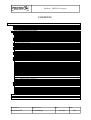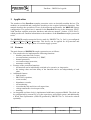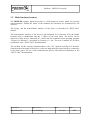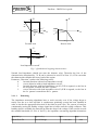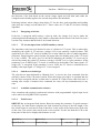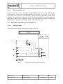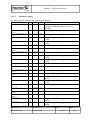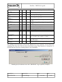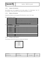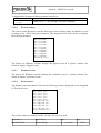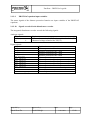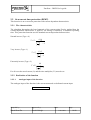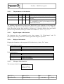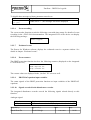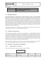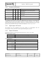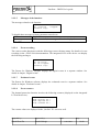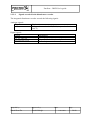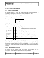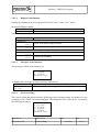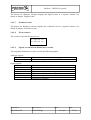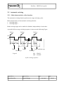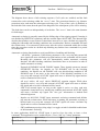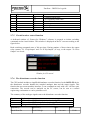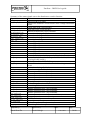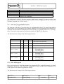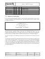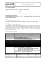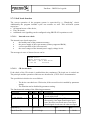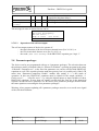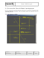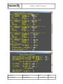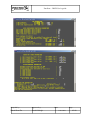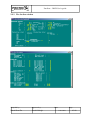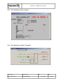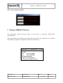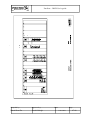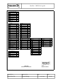
1
PROTECT Electronics Co. Ltd EuroProt complex protection DRFP-EP factory configuration ID. No.: FR-13-13860-01 Budapest, 2004 PROTECT EuroProt – DRFP User’s guide Electronics Co. Ltd CONTENTS 1 APPLICATION ........................................................................................................................................... 3 1.1 1.2 2 FEATURES .................................................................................................................................................. 3 MAIN HARDWARE FEATURES ..................................................................................................................... 4 THE PROTECTION FUNCTIONS........................................................................................................... 5 2.1 DISTANCE PROTECTION WITH 5 INDEPENDENT ZONES ............................................................................... 5 2.1.1 Distance characteristics .................................................................................................................. 5 2.1.2 Realisation of distance protection function ..................................................................................... 8 2.2 OVERCURRENT TIME PROTECTION (IDMT) ............................................................................................. 14 2.2.1 The characteristics ........................................................................................................................ 14 2.2.2 Realisation of the function............................................................................................................. 14 2.3 THERMAL PROTECTION ............................................................................................................................ 17 2.3.1 Principle of measurement.............................................................................................................. 17 2.3.2 Realisation of thermal protection function.................................................................................... 17 2.4 OVER/UNDERVOLTAGE PROTECTION ....................................................................................................... 21 2.4.1 Principle of measurement.............................................................................................................. 21 2.4.2 Realisation of over/undervoltage protection function ................................................................... 21 2.5 AUTOMATIC RECLOSING .......................................................................................................................... 24 2.5.1 Main characteristics of the function.............................................................................................. 24 2.5.2 Realisation of the function............................................................................................................. 26 2.6 BREAKER FAILURE PROTECTION .............................................................................................................. 28 2.7 ADDITIONAL IMPLEMENTED FUNCTIONS .................................................................................................. 29 2.7.1 PROTLOG equations .................................................................................................................... 29 2.7.2 Application of signals from the digital inputs ............................................................................... 32 2.7.3 Application of output relays .......................................................................................................... 32 2.7.4 Application of the analogue outputs.............................................................................................. 32 2.7.5 Circuit breaker control function.................................................................................................... 33 2.7.6 The disturbance recorder function ................................................................................................ 33 2.7.7 The free programmable timers ...................................................................................................... 35 2.7.8 The LED signals ............................................................................................................................ 35 2.7.9 Displayed system messages ........................................................................................................... 36 2.7.10 I2t measurement............................................................................................................................. 37 2.7.11 Frequency measurement ............................................................................................................... 37 2.7.12 Displayed values (Summary)......................................................................................................... 37 2.7.13 Self check function......................................................................................................................... 38 2.8 PARAMETER PACKAGES ........................................................................................................................... 39 2.9 THE SCREENS OF THE “PROTECT FOR WINDOWS” OPERATING PROGRAM ................................................ 40 2.9.1 The Parameters window................................................................................................................ 40 2.9.2 The On-line window ...................................................................................................................... 43 The Evaluated events window...................................................................................................................... 44 The Equations window (Example) ............................................................................................................... 44 2.9.5 The Controls window .................................................................................................................... 45 3 DESIGN OF DRFP-EP DEVICES........................................................................................................... 45 4 DRAWINGS............................................................................................................................................... 46 Compiled by: Approved by: Kornél Petri Dr. László Balogh Date: 11.09.2004. Page: 2/48 PROTECT EuroProt – DRFP User’s guide Electronics Co. Ltd 1 Application The members of the EuroProt complex protection series are basically modular devices. The modules are assembled and configured according to the required protection functions. This manual describes the specialities of one of the numerous applications: the DRFP-EP factory configuration. The general user’s manual for the EuroProt devices is the document „EPCP2004 EuroProt complex protection, hardware and software manual”, (further „EPCP-2004”), which provides all common information to the members of the EuroProt complex protection series. The DRFP-EP complex numerical device made by PROTECTA Co. Ltd. is pre-configured for Digital Railway Feeder Protection. This device can be applied for all protection and auxiliary functions for single phase AC traction supply systems. 1.1 Features The main features of DRFP-EP complex protection are as follows: The complex device implements the following functions: − distance protection with 5 zones, − overcurrent time protection (I>>) IDMT, − thermal protection, − over/undervoltage protection, − automatic reclosing. Features of the protection functions: − all functions can be individually switched to be operative or inoperative; − the setting values and time delay of the functions can be set independently of each other. Additional features: − fault location, − PROTLOG equations, − event recorder, − disturbance recorder, − self monitoring, − circuit breaker trip and close coil supervision, − voltage transformer circuit supervision, − metering. An integrated real-time clock is implemented with battery supported RAM. The clock can be synchronised by external PC or by the supervisory and control system, and additionally a Word Time Synchroniser (GPS-OP) produced by PROTECTA Co. Ltd can be ordered optionally. Compiled by: Approved by: Kornél Petri Dr. László Balogh Date: 11.09.2004. Page: 3/48 PROTECT EuroProt – DRFP User’s guide Electronics Co. Ltd 1.2 Main hardware features The DRFP-EP complex digital protection is a full numerical system, based on powerful microcontrollers. Within the limits of the hardware the functions are determined by the software. The design, and the man-machine interface of the device is described in „EPCP-2004” manual. The man-machine interface of the device is the integrated 2x16 character LCD, the simple keyboard with 6 pushbuttons and the 7 LED-s on the front panel. The device can be supervised easier with a connected PC, which runs the windows-based operating program „Protect for Windows”, developed by Protecta Co. Ltd. The user’s manual for all these possibilities is the „EPCP-2004” documentation. The medium for the external communication is the 2 kV isolated serial RS 232 interface located on the front panel of the device, or the two integrated fibre optic interfaces, connectors on the back panel. For the serial communication please find detailed information in the „EPCP-2004” documentation. Compiled by: Approved by: Kornél Petri Dr. László Balogh Date: 11.09.2004. Page: 4/48 PROTECT EuroProt – DRFP User’s guide Electronics Co. Ltd 2 The protection functions The DRFP-EP complex numerical protection implements the following protection functions for single phase AC traction supply systems: − − − − − distance protection with 5 zones, overcurrent time protection (IDMT), thermal protection, over/undervoltage protection, automatic reclosing. These functions are independent of each other, they can be set individually. The functions can be individually set to be operative or inoperative. The following chapters describe the protection functions. 2.1 Distance protection with 5 independent zones One of the basic functions of the complex protection is the distance protection. For the first zone the operation is based on three sampled voltage and current values. This algorithm is very fast, and insensitive of CT saturation. The operation of the first zone protection is dependent on the starting of a dedicated undervoltage function as well. For the other four zones the algorithm operates with Fourier filtering. Using this method the operation is optimised for distorted waveform. If the calculated impedance is within the polygon characteristics of the zone, the function starts the timer. When the pre-set time is over the function generates trip command. 2.1.1 Distance characteristics Zone 1 is directed forward, the operation depends on undervoltage function. Zone 2 is directed forward, and can operate with load impedance cut-off. Zone 3 and 4 can be directed forward or backward, and can operate with load impedance cut-off. Zone 5 has reverse direction. Each of the zones has a quadrilateral characteristics. Parameters of the characteristics are as follows: Undervoltage control for zone 1, Resistive reach individually for each zones, Reactive reach individually for each zones, -R/X angular coefficient individually for each zones, -X/R angular coefficient individually for each zones, Direction (for zones 3 and 4) and load impedance cut-off (for zones 2, 3 and 4). Compiled by: Approved by: Kornél Petri Dr. László Balogh Date: 11.09.2004. Page: 5/48 PROTECT EuroProt – DRFP User’s guide Electronics Co. Ltd X jX jX −R X −X R R R R -R -X Forward zone Reverse zone jX R -X R Load impedance cut-off Fig. 1 Quadrilateral tripping characteristics. Normal load impedance should not start the distance relay. Therefore the line of the characteristics determined by –X/ R can be mirrored to axis R in Zone 2,3,4. This can make the characteristics blind to the heavy load of the engine. Parameter „Direction” can have the following values: 0: forward direction with no load impedance cut-off; 1: reverse direction with no load impedance cut-off; 2: forward direction with load impedance cut-off (-X/R is negated, so the line in the 4th quarter is turned into the 1st quarter; 3: reverse direction with load impedance cut-off (-X/R is negated, so the line in the 2nd quarter is turned into the 3rd quarter. 2.1.1.1 Polarising The impedance measuring algorithms have to work correctly even if the voltage drops to nearly zero due to a close-up fault. A synchronous polarising system has been installed in order to decide the appropriate direction of the fault in such cases. The system is based on continuously storing the healthy voltage signal into a buffer until the voltage collapses. This healthy signal is available for about 80 ms after the drop of the voltage. If the current exceeds the minimal threshold (25-30% of In(CT)), the impedance measuring algorithm determines Compiled by: Approved by: Kornél Petri Dr. László Balogh Date: 11.09.2004. Page: 6/48 PROTECT EuroProt – DRFP User’s guide Electronics Co. Ltd the direction of the fault based on the stored voltage signal and will latch until either the voltage becomes healthy again or the current drops below the threshold. Polarising initiates when voltage drops below 5V for the three point algorithm and latching ends when the voltage exceeds about 40 V. These values are 5V and 8V at Fourier filtering algorithm. 2.1.1.2 Energising of the line If the line is energised while having a close-up fault, the voltage level can be under the polarising threshold making the relay unable to determine the direction of the fault. In such a case the relay assumes that the fault is in forward direction. 2.1.1.3 VT circuit supervision via MCB auxiliary contact The impedance relay has to be blocked in case of a failure in VT circuit. This is achieved by monitoring the signal of VT miniature (midget) CB via an optically coupled isolator. This signal has to be active (VT circuit is healthy) for at least 200ms in order to enable impedance protection. Energising this optical isolator can mean either the healthy state of the VT circuit or it has a failure. The active level of the MCB indicating the healthy VT circuit can be selected by setting the related VT miniature (midget) CB OK level on input parameter. If this parameter is set to HIGH, the VT circuit is considered to be healthy if the input signal “VT midget CB” is energised. If the parameter is set to LOW, the VT circuit is considered to be healthy if the input signal “VT midget CB” is not energised. 2.1.1.4 Switch-on-to-fault logic The relay has an input dedicated as “Manual close” to receive the close command from the auxiliary contact of the CB control switch. When this input goes high it is assumed that the line has been energised and the reclaim timer is started. If a fault occurs while this timer is running after receipt of manual close command, the relay will trip instantaneously in any zone. 2.1.1.5 Available communication schemes Zone extension and permissive underreach schemes with programmable logical input levels can be achieved using PROTLOG equations. 2.1.1.6 Fault locator DRFP-EP has an integrated fault locator. Based on setting the parameter Xn (total reactance of the line), the fault locator calculates the fault location in percent of the full length of the line. Fault locator is activated in Zone 2 therefore it only works if the fault occurs in the area of this zone. The result is also stored in the event recorder. For the last fault the LCD on the front panel of the device displays this distance as well. Compiled by: Approved by: Kornél Petri Dr. László Balogh Date: 11.09.2004. Page: 7/48 PROTECT EuroProt – DRFP User’s guide Electronics Co. Ltd 2.1.1.7 Inactivating the zones Each zone can be set to be inoperative using PROTLOG system. A user defined logic equation can be set to block the zone from tripping (Z1 trip block, Z2 trip block, Z3 trip block, Z4 trip block, Z5 trip block). The measuring, starting and timing procedure remains active while the zone trip is blocked, this way the user has the opportunity to use a zone element for signalling or other purposes. Blocking the trip of the zone forces the protection starting and tripping logic to ignore the start and trip signals of the appropriate zone. 2.1.2 Realisation of distance protection function 2.1.2.1 Analogue inputs This function measures the current and the voltage of the line: I (CT Z<) U (VT) Figure 2 Correctly directed external connections Compiled by: Approved by: Kornél Petri Dr. László Balogh Date: 11.09.2004. Page: 8/48 PROTECT EuroProt – DRFP User’s guide Electronics Co. Ltd 2.1.2.2 Parameter setting The function needs setting of the following parameters: LCD Min Max Step Explanation U<Z1 ( /Un[VT]) = 5 120 1 Voltage setting of the first zone undervoltage % function, below which the first zone is operable. R1 (*10*Cu*Ci) = 10 10000 10 R setting of the polygon mOhm X1 (*10*Cu*Ci) = mOhm -R1/X1 = % X setting of the polygon 10 10000 10 0 50 1 -X1/R1 = % 0 50 1 t ( Z1< ) = ms R2 (*10*Cu*Ci) = mOhm X2 (*10*Cu*Ci) = mOhm -R2/X2 = % 0 60000 10 Angle setting of the polygon in negative R reach Angle setting of the polygon in negative X reach Time delay 10 20000 10 R setting of the polygon 10 20000 10 X setting of the polygon 0 50 1 -X2/R2 = % 0 200 1 Z2 direction /0, 2/ t ( Z2< ) = ms R3 (*10*Cu*Ci) = mOhm X3 (*10*Cu*Ci) = mOhm -R3/X3 = % 0 2 2 0 60000 10 Time delay 10 20000 10 R setting of the polygon 10 20000 10 X setting of the polygon 0 50 1 -X3/R3 = % 0 200 1 Z3 direction /0..3/ t ( Z3< ) = ms R4 (*10*Cu*Ci) = mOhm X4 (*10*Cu*Ci) = mOhm -R4/X4 = % 0 3 1 0 60000 10 Time delay 10 20000 10 R setting of the polygon 10 20000 10 X setting of the polygon 0 50 1 0 200 1 -X4/R4 = % Compiled by: Approved by: Kornél Petri Dr. László Balogh Angle setting of the polygon in negative R reach Angle setting of the polygon in negative X reach Load impedance cut-off Angle setting of the polygon in negative R reach Angle setting of the polygon in negative X reach Direction and load impedance cut-off Angle setting of the polygon in negative R reach Angle setting of the polygon in negative X reach Date: 11.09.2004. Page: 9/48 PROTECT EuroProt – DRFP User’s guide Electronics Co. Ltd Z4 direction /0..3/ t ( Z4< ) = ms R5 (*10*Cu*Ci) = mOhm X5 (*10*Cu*Ci) = mOhm -R5/X5 = % Direction and load impedance cut-off 0 3 1 0 60000 10 Time delay 10 20000 10 R setting of the polygon 10 20000 10 X setting of the polygon 0 50 1 -X5/R5 = % 0 50 1 t ( Z5< ) = ms XnLine*10*Cu*Ci= mOhm Line length [km] 0 60000 10 Angle setting of the polygon in negative R reach Angle setting of the polygon in negative X reach Time delay 100 20000 10 Total reactance of the line 0 1000 1 CT primary nom= A 100 2500 1 VT primary nom/10= V VT MCB OK level /+=HIGH/ 100 6000 1 - + - + 2nd trip.coil? /+=yes/ Total length of the line in km CT primary rated current VT primary rated voltage divided by 10 (e.g. for 120’000 V this value is 12’000) Voltage level indicating the healthy state of the VT circuit Second trip coil is to be operated The enabling of the functions is solved with „PROTLOG” logic equations. As an example the enabling of the first zone (The Fig. shows the default setting. If the check-box “Always on” is checked, then the first zone cannot generate a trip command.): Enabling the first distance zone with „PROTLOG” logic equation (example) Compiled by: Approved by: Kornél Petri Dr. László Balogh Date: 11.09.2004. Page: 10/48 PROTECT EuroProt – DRFP User’s guide Electronics Co. Ltd 2.1.2.3 Outputs of the function The functions give trip command on the relay contacts “To I.Trip.Output” and “To II.Trip.Output” (if any), and deliver status signals indicating the operation. 2.1.2.4 Displayed information Displayed information on the integrated LCD of the device, in the „Test” menu: Measured analogous signals: LCD information Explanation I (Z) = [A] Measured current U = [V] Measured voltage R sec. [Ohm]= Calculated resistance value in secondary Ohms*Cu*Ci X sec. [Ohm]= Calculated reactance value in secondary Ohms*Cu*Ci Fault loc. = [km] Distance to fault for the last event, in km Digital information: LCD information Explanation 1. status bits: Z1 pos.1 Z2 pos.2 Z3 pos.3 Z4 pos.4 Z5 pos.5 Distance protection start in zone 1 Distance protection start in zone 2 Distance protection start in zone 3 Distance protection start in zone 4 Distance protection start in zone 5 2. status bits: Start pos.2 Trip pos.3 General start signal General trip command 2.1.2.5 Messages of the function: The messages on the LCD of the device related to the function: Z1< tripped! Z2< tripped! Z3< tripped! Z4< tripped! Z5< tripped! Definite trip! Compiled by: Approved by: Kornél Petri Dr. László Balogh Date: 11.09.2004. Page: 11/48 PROTECT EuroProt – DRFP User’s guide Electronics Co. Ltd To disable these messages a binary parameter must be set: LCD Explanation Block oper.mess. When set to “+”, the messages will not be displayed /+= yes/ 2.1.2.6 Event recording The event recorder function records the following events with time stamp. See details of event recording in the „EPCP-2004 documentation. The integrated LCD of the device can display the following messages: Z1< started! Z2< started! Z3< started! Z4< started! Z5< started! Z1< tripped! Z2< tripped! Z3< tripped! Z4< tripped! Z5< tripped! Definite trip! The Protect for Windows software displays the digital events in a separate window. See details in chapter “Digital events”. 2.1.2.7 Evaluated events The Protect for Windows software displays the evaluated event in a separate window. See details in chapter “Evaluated events”. 2.1.2.8 Event counters The distance protection function involves the following counters (displayed on the integrated LCD of the device): Z1< start cnt= Z2< start cnt= Z3< start cnt= Z4< start cnt= Z5< start cnt= Z1< expired cnt= Z2< expired cnt= Z3< expired cnt= Z4< expired cnt= Z5< expired cnt= Trip command cnt= The counter values are displayed in the „On-line” PC screen as well. Compiled by: Approved by: Kornél Petri Dr. László Balogh Date: 11.09.2004. Page: 12/48 PROTECT EuroProt – DRFP User’s guide Electronics Co. Ltd 2.1.2.9 PROTLOG equation input variables The status signals of the distance protection function are input variables of the PROTLOG equations. 2.1.2.10 Signals recorded in the disturbance recorder The integrated disturbance recorder records the following signals: Analogue signals: Signal I (Z) % U % Digital signals: Signal Z1_started Z2_started Z3_started Z4_started Z5_started Z1t_expired Z2t_expired Z3t_expired Z4t_expired Z5t_expired Start Protection_trip Explanation Measured current in the CT(Z<) input related to the In(CT) Measured voltage related to the Vn(VT) Explanation Distance protection Zone 1 start Distance protection Zone 2 start Distance protection Zone 3 start Distance protection Zone 4 start Distance protection reverse zone start Distance protection Zone 1 trip command Distance protection Zone 2 trip command Distance protection Zone 3 trip command Distance protection Zone 4 trip command Distance protection reverse zone trip command General start General trip command Compiled by: Approved by: Kornél Petri Dr. László Balogh Date: 11.09.2004. Page: 13/48 PROTECT EuroProt – DRFP User’s guide Electronics Co. Ltd 2.2 Overcurrent time protection (IDMT) This function is an overcurrent protection with current dependent characteristics. 2.2.1 The characteristics The algorithm determines the base harmonic of the current using Fourier method then the current dependent characteristic is applied. The timing is limited by a minimum operating time. This protection function uses the standard current dependent characteristics: Normal inverse (Type =0) T = TN 0.14 I IN 0.02 −1 Very inverse (Type =1) T = TN 13.5 I IN 1 − 1 Extremely inverse (Type =2) 80 T = TN 2 I − 1 IN For all cases the rated current (IN) and the time multiplier (TN) must be set. 2.2.2 Realisation of the function 2.2.2.1 Analogue input of the function The analogue input of the function is the current measured on dedicated current input: Iv CT(Z<) Compiled by: Approved by: Kornél Petri Dr. László Balogh Date: 11.09.2004. Page: 14/48 PROTECT EuroProt – DRFP User’s guide Electronics Co. Ltd 2.2.2.2 The parameters of the function LCD text Min Max IDMT type(0,1,2) IDMT M const. 0 1 Ibasic/Ctnom*100 % 20 Step Explanation 1 (0: inverse, 1: very inverse, 2: extremely inverse) 1 Time multiplier multiplied by 20 (M) M=20*TN 150 1 Current setting, related to the rated current of the CT, multiplied by 100 (E.g. for setting of 0.5 the value to be set is 50) 2 256 The enabling of the functions is solved with „PROTLOG” logic equations. As an example the enabling of the first zone of the distance protection is shown in Chapter 2.1.2.2. (The Fig. shows the default setting. If the check-box “Always on” is checked, then the first zone cannot generate a trip command.) The logic variable to be handled is: “IDMT trip block” 2.2.2.3 Digital outputs of the function The functions give trip command on the relay contacts “To I.Trip.Output” and “To II.Trip.Output” (if any), and deliver status signals indicating the operation. 2.2.2.4 Displayed information Displayed information on the integrated LCD of the device, in the „Test” menu: Measured analogous signals: LCD information Explanation I (Z) = [A] Measured current IDMT = Countdown starting at 1000 if the function operates Digital information: LCD information 2. status bits: Start pos.2 Trip pos.3 2.2.2.5 Explanation General start signal General trip command Messages of the function: The messages related to the function are: IDMT tripped! Definite trip! Compiled by: Approved by: Kornél Petri Dr. László Balogh Date: 11.09.2004. Page: 15/48 PROTECT EuroProt – DRFP User’s guide Electronics Co. Ltd To disable these messages a binary parameter must be set: LCD Explanation Block oper.mess. When set to “+”, the messages will not be displayed /+= yes/ 2.2.2.6 Event recording The event recorder function records the following event with time stamp. See details of event recording in the „EPCP-2004 documentation. The integrated LCD of the device can display the following message: IDMT tripped! 2.2.2.7 Evaluated events The Protect for Windows software displays the evaluated event in a separate window. See details in chapter “Evaluated events”. 2.2.2.8 Event counters The IDMT protection function involves the following counters (displayed on the integrated LCD of the device): IDMT expired cnt Trip command cnt The counter values are displayed in the „On-line” PC screen as well. 2.2.2.9 PROTLOG equation input variables The status signals of the IDMT protection function are input variables of the PROTLOG equations. 2.2.2.10 Signals recorded in the disturbance recorder The integrated disturbance recorder records the following signals related directly to this function: Analogue signal: Signal I (Z) Explanation % Measured current in the CT(Z<) input related to the In(CT) Compiled by: Approved by: Kornél Petri Dr. László Balogh Date: 11.09.2004. Page: 16/48 PROTECT EuroProt – DRFP User’s guide Electronics Co. Ltd Digital signal: Signal IDMT_expired Protection_trip Explanation Trip command of the IDMT function General trip command 2.3 Thermal protection The electrical equipment (overhead lines, motors, transformers, cables, etc.) can withstand high overload current for a short time, but a relatively small overcurrent, which flows for a long time can lead to overheating and damages of the equipment. The current dependent inverse type characteristics disconnect the circuit breaker quicker if the current increases, but they cannot provide suitable protection against overheating. This is because a considerably longer time is needed to reach the critical temperature, if the heating starts in a cold state, then in case of starting in a warm operating state. This problem is solved by the thermal overload protection, which calculates the temperature based on the measured current. If the temperature approaches the critical temperature, the function generates a warning signal, and at the critical temperature trips the circuit breaker. Calculation of temperature rise will be reset (the calculated over-temperature will be set to 0) after switching on the relay or downloading the parameter set. 2.3.1 Principle of measurement The temperature of equipment - relatively to the environment - is determined by the balance of the internal generated heat and the heat radiated into the environment. Based on this physical model a differential equation can be established, the step-by-step solution of which is the principle of the thermal overload protection. If the thermal parameters of the equipment are known, then based on the measured current the thermal state (temperature) of the equipment can be calculated continuously. The algorithm “remembers” the former load current, and takes the natural cooling into consideration as well. If the temperature approaches the setting value of the warning temperature, the protection generates a warning signal, and at the critical temperature trips the circuit breaker. 2.3.2 Realisation of thermal protection function 2.3.2.1 Analogue inputs of the function The function measures the current on a dedicated input CT(ThOL): I CT(ThOL) Compiled by: Approved by: Kornél Petri Dr. László Balogh Date: 11.09.2004. Page: 17/48 PROTECT EuroProt – DRFP User’s guide Electronics Co. Ltd 2.3.2.2 Parameters of the function LCD text Min Max Θt/Θn (trip) = % 80 250 Θpre/Θn (alarm)= % 80 250 In(line)/In(CT)= % 10 500 Θn(nom.overheat) ºC Time constant = s 0 200 Step Explanation 1 Trip temperature as percent of the rated temperature 1 Alarm temperature as percent of the rated temperature 1 Rated current of the line as percent of the rated CT current 1 Rated over-temperature at rated current 0 2000 1 Thermal time constant The enabling of the functions is solved with „PROTLOG” logic equations. As an example the enabling of the first zone of the distance protection is shown in Chapter 2.1.2.2. (The Fig. shows the default setting. If the check-box “Always on” is checked, then the first zone can not generate a trip command.) The logic variable to be handled is: “ThOL trip block” 2.3.2.3 Digital outputs of the function The functions give trip command on the relay contacts “To I.Trip.Output” and “To II.Trip.Output” (if any), and deliver status signals indicating the operation. 2.3.2.4 Displayed information Displayed information on the integrated LCD of the device, in the „Test” menu: Measured analogous signals: LCD information Explanation I (Th) = [%] Measured current related to the In(CT) Overtemp. [ºC] Calculated temperature above the ambient temperature Digital information: LCD information 1. status bits: Explanation Signal of the thermal protection ThWarn pos.6 2. status bits: Trip command of the thermal protection ThTrip pos.1 General start signal Start pos.2 General trip command Trip pos.3 Compiled by: Approved by: Kornél Petri Dr. László Balogh Date: 11.09.2004. Page: 18/48 PROTECT EuroProt – DRFP User’s guide Electronics Co. Ltd 2.3.2.5 Messages of the function: The messages related to the function: Th. overload Definite trip! tripped! To disable these messages a binary parameter must be set: LCD Explanation Block oper.mess. When set to “+”, the messages will not be displayed /+= yes/ 2.3.2.6 Event recording The event recorder function records the following events with time stamp. See details of event recording in the „EPCP-2004 documentation. The integrated LCD of the device can display the following messages: Th. OL alarm! Th. OL tripped! Definite trip! The Protect for Windows software displays the digital events in a separate window. See details in chapter “Digital events”. 2.3.2.7 Evaluated events The Protect for Windows software displays the evaluated event in a separate window. See details in chapter “Evaluated events”. 2.3.2.8 Event counters The thermal protection function involves the following counters (displayed on the integrated LCD of the device): ThOL warning cnt = ThOL expired cnt = Trip command cnt = The counter values are displayed in the „On-line” PC screen as well. Compiled by: Approved by: Kornél Petri Dr. László Balogh Date: 11.09.2004. Page: 19/48 PROTECT EuroProt – DRFP User’s guide Electronics Co. Ltd 2.3.2.9 Signals recorded in the disturbance recorder The integrated disturbance recorder records the following signals: Analogue signals: Signal IvTh % Digital signals: Signal Th.OL_prealarm Th.OL_expired Protection_trip Explanation Measured current in the CT(ThOL) input related to the In(CT) Explanation Warning signal of the thermal protection Trip command of the thermal protection General trip command Compiled by: Approved by: Kornél Petri Dr. László Balogh Date: 11.09.2004. Page: 20/48 PROTECT EuroProt – DRFP User’s guide Electronics Co. Ltd 2.4 Over/undervoltage protection 2.4.1 Principle of measurement The algorithm measures the voltage, and for this voltage the base Fourier component is calculated. The function starts, if the voltage is above / below the setting value. 2.4.2 Realisation of over/undervoltage protection function 2.4.2.1 Analogue inputs of the function The analogue input signal of the function is the voltage: Uv 2.4.2.2 The parameters of the function The function needs setting of the following parameters: LCD text Min Max Step U< (/Un[VT])= % 5 120 1 U> (/Un[VT])= % 70 130 1 100 6000 1 0 60000 1 Explanation Voltage setting value for the undervoltage function related to the voltage transformer rated value Voltage setting value for the overvoltage function related to the voltage transformer rated value Primary rated voltage of the voltage transformer divided by 10 calculated for the rated voltage of the voltage input (110 V) Delay time of the undervoltage function 0 60000 1 Delay time of the overvoltage function VT primary nom./10= V t(U<) = ms t(U>) = ms The enabling of the functions is solved with „PROTLOG” logic equations. As an example the enabling of the first zone of the distance protection is shown in Chapter 2.1.2.2. (The Fig. shows the default setting. If the check-box “Always on” is checked, then the first zone can not generate a trip command.) The logic variables to be handled are: “U< trip block” and “U> trip block”. The trip command of the over/undervoltage function is allways a definite trip command. 2.4.2.3 Digital outputs of the function The functions give trip command on the relay contacts “To I.Trip.Output” and “To II.Trip.Output” (if any), and deliver status signals indicating the operation. Compiled by: Approved by: Kornél Petri Dr. László Balogh Date: 11.09.2004. Page: 21/48 PROTECT EuroProt – DRFP User’s guide Electronics Co. Ltd 2.4.2.4 Displayed information Displayed information on the integrated LCD of the device, in the „Test” menu: Measured analogue signals: LCD information Explanation U = [V] Measured voltage Digital information: LCD information 1. status bits: Explanation Signal of the undervoltage function Uk pos.7 Signal of the overvoltage function Un pos.8 2. status bits: General start signal Start pos.2 General trip command Trip pos.3 2.4.2.5 Messages of the function: The messages related to the function are: U< tripped! U> tripped! Definite trip! To disable these messages a binary parameter must be set: LCD Explanation Block oper.mess. When set to “+”, the messages will not be displayed /+= yes/ 2.4.2.6 Event recording The event recorder function records the following events with time stamp. See details of event recording in the „EPCP-2004 documentation. The integrated LCD of the device can display the following messages: U< started! U> started! U< tripped! U> tripped! Definite trip! Compiled by: Approved by: Kornél Petri Dr. László Balogh Date: 11.09.2004. Page: 22/48 PROTECT EuroProt – DRFP User’s guide Electronics Co. Ltd The Protect for Windows software displays the digital events in a separate window. See details in chapter “Digital events”. 2.4.2.7 Evaluated events The Protect for Windows software displays the evaluated event in a separate window. See details in chapter “Evaluated events”. 2.4.2.8 Event counters The counters related to the function are: U< expired cnt U> expired cnt 2.4.2.9 Signals recorded in the disturbance recorder The integrated disturbance recorder records the following signals: Analogue signals: Signal U [%] Digital signals: Signal U>_started U<_started U>_expired U<_expired Start Protection_trip Explanation Measured voltage related to the Vn(VT) Explanation Start of the overvoltage function Start of the undervoltage function Trip command of the overvoltage function Trip command of the undervoltage function General start signal General trip command Compiled by: Approved by: Kornél Petri Dr. László Balogh Date: 11.09.2004. Page: 23/48 PROTECT EuroProt – DRFP User’s guide Electronics Co. Ltd 2.5 Automatic reclosing 2.5.1 Main characteristics of the function The automatic reclosing function performs two stage reclosing cycles. Main characteristics of the automatic reclosing function: • reclosing stage 1 • reclosing stage 2 Both reclosing stages can be enabled or disabled, independently of each other. A possible full two stage reclosing sequence is shown on the following Figure. Fault 1 Fault 2 Fault 3 ON. OFF t trip1 tdead1 t trip2 tdead2 t trip3 treclaim Trip 1 treclaim Trip 2 Reclosing 1 Trip 3 (definite trip) Rclosing 2 ON : CB ON OFF : CB OFF Legend: A full reclosing sequence Compiled by: Approved by: Kornél Petri Dr. László Balogh Date: 11.09.2004. Page: 24/48 PROTECT EuroProt – DRFP User’s guide Electronics Co. Ltd The diagram above shows a full reclosing sequence, if all cycles are enabled, and the fault returns after each reclosing within the “treclaim” time. The protection function (e.g. distance protection) trips, and starts the subsequent reclosing cycle. If any of the cycles is disabled, or the fault does not return, then the part of the diagram or the subsequent cycles will be missing. The dead times can be set independently of each other. The “t reclaim” time is the same duration for both stages. Automatic reclosing is generally started by the falling edge of the tripping signal (if starting is not disabled by PROTLOG equations) and the external input AR START. The internal logic decides then whether to start a timer for dead time interval or to issue a definite trip signal, by taking the AR enable and blocking conditions into consideration. Reclose command will start the reclaim timer. If a consecutive fault occurs after the reclose command within the reclaim time, the procedure results in a definite trip blocking any further close command for a period of reclaim time. Automatic reclosing function has several possibilities of enabling and blocking. - „AR disable” parameter. If this binary parameter is set, every trip and external AR start signal will cause a definite trip signal and no reclose command will be issued. Resetting this parameter will not automatically enable automatic reclosing function. All other blocking conditions listed below have to be inactive in order to enable automatic reclosing. - External AR DISABLE and AR ENABLE signals. These signals operate an internal SET/RESET flip-flop. An impulse on AR DISABLE will set the blocking condition. An impulse on AR ENABLE will reset this blocking condition if AR DISABLE input is not active at the same time. If this blocking condition is set, every trip and external AR START signal will cause a definite trip signal and no reclose command will be issued. - AR step1 inhibit, AR step2 inhibit PROTLOG equation outputs. While these signals are active, every trip and external AR START signal will cause a definite trip signal and no reclose command will be issued. - LOW GAS external input. As long as this signal is active, no close (and trip) command is issued and every internal trip condition and external AR START signal will cause a definite trip signal. The “low gas” information is latched until acknowledgement. - Impulse on MANUAL CLOSE input, automatic reclosing command and definite trip start the reclaim timer. While this timer is running, the automatic reclosing is blocked and every trip and external AR START signal will cause a definite trip signal and no reclose command will be issued. - SW2 pushbutton pressing (rising edge) is a toggle switch for disabled/enabled state of the automatic reclosing. In some application MANUAL CLOSE input is used to force the relay to issue a close command. This application can be enabled by the „Close if MC inp” binary parameter. Compiled by: Approved by: Kornél Petri Dr. László Balogh Date: 11.09.2004. Page: 25/48 PROTECT EuroProt – DRFP User’s guide Electronics Co. Ltd Control commands on serial communication can force the relay to issue a trip or a close command. A remote trip command in this case will always act like a definite trip and a remote close command will act as if it were a manual close. The duration of the close command issued by the relay can be determined by the „t (Close)” parameter. 2.5.2 Realisation of the function 2.5.2.1 Analogue inputs of the function The function does not need independent analogue input values, the triggering is performed by other protection functions (distance protection, overcurrent protection, etc.) or an external command received on a digital input can initiate reclosing as well. 2.5.2.2 The parameters of the function The function needs setting of the following parameters: LCD text t1 (Dead time)= s t2 (Dead time)= s t (Close) = ms t (Trip min.)= ms t (Reclaim) = ms Z1< start AR ? /+=yes/ Min Max Step 0 600 1 Explanation Dead time for the first reclosing 0 600 1 Dead time for the second reclosing 0 60000 10 Impulse time of the close command 0 60000 10 Minimal impulse time of the trip command 0 60000 10 Reclaim time Distance protection Zone 1 starts automatic reclosing Distance protection Zone 2 starts automatic reclosing Distance protection Zone 3 starts automatic reclosing Distance protection Zone 4 starts automatic reclosing IDMT overcurrent function starts automatic reclosing Automatic reclosing disabled, no other means for enabling is possible Z2< start AR ? /+=yes/ Z3< start AR ? /+=yes/ Z4< start AR ? /+=yes/ IDMT start AR ? /+=yes/ AR disable /+=yes/ Compiled by: Approved by: Kornél Petri Dr. László Balogh Date: 11.09.2004. Page: 26/48 PROTECT EuroProt – DRFP User’s guide Electronics Co. Ltd 2.5.2.3 Digital outputs of the function The function gives trip command on the relay contacts “To I.Trip.Output” and “To II.Trip.Output” (if any), delivers status signals indicating the operation. The close command is generated to output “To Close Output”. 2.5.2.4 Displayed information Digital information: LCD information 2. status bits: Explanation General trip command Trip pos.3 Automatic reclosing function is disabled AR disabled pos.4 2.5.2.5 Messages of the function: The messages related to the function: Definite trip! 1.auto reclose! 2.auto reclose! To disable these messages a binary parameter must be set: LCD Block oper.mess. /+= yes/ 2.5.2.6 Explanation When set to “+”, the messages will not be displayed Event recording On the LCD of the device the displayed events related to the function are as follows: AR was blocked! Aut. reclose! Definite trip! The Protect for Windows software displays the digital events in a separate window. See details in chapter “Digital events”. Compiled by: Approved by: Kornél Petri Dr. László Balogh Date: 11.09.2004. Page: 27/48 PROTECT EuroProt – DRFP User’s guide Electronics Co. Ltd 2.5.2.7 Evaluated events The Protect for Windows software displays the evaluated event in a separate window. See details in chapter “Evaluated events”. 2.5.2.8 Event counters The counter related to this function counts the close commands: Close command cnt 2.5.2.9 Signals recorded in the disturbance recorder The integrated disturbance recorder records the following signals: Digital signals: Signal AR_disable_input AR_enable_input AR_start_input SW2_AR_dis/en. AR_blocked Man._close_inp. Trip command Protection_trip Close command Definitive trip Explanation Status of the input AR DISABLE Status of the input AR ENABLE Status of the input AR START Status of the input SW2 pushbutton Blocked state of the automatic reclosing Status of the input MANUAL CLOSE Trip command General trip command Close command Definitive trip command 2.6 Breaker failure protection If any of the protection functions generates a trip command and the CB is closed then the timer of the CB failure protection starts. (The CB status is indicated by the two dedicated digital inputs CB CLOSED and CB OPEN. In case of contradiction a timer is started the expiry of which indicates “CB discrepancy”.) The timer of the CB failure protection can be stopped by the open state of the CB. If the delay time expires, the following status variables are set to logic “1” state: “CB failure”, “Definitive trip” and “AR disabled”. The function needs setting of the following parameters: Min Max Step t(CB failure)= ms LCD text 0 60000 10 t(CB discrep)= 0 60000 10 Compiled by: Approved by: Kornél Petri Dr. László Balogh Explanation Delay time for the CB failure protection function Delay time for the CB discrepancy state Date: 11.09.2004. Page: 28/48 PROTECT EuroProt – DRFP User’s guide Electronics Co. Ltd The messages of the function are: CB status discrepancy CB failure 2.7 Additional implemented functions 2.7.1 PROTLOG equations The available digital status signals are the input variables of the PROTLOG equation system, which can be „freely” programmed to set output variables of the equation system. 2.7.1.1 Inputs of the logic equations The available inputs for the logic equations are listed in the following table: Input Low gas inp. VT midget CB OK CB closed inp. CB open inp. Man. close inp. AR disable inp. AR enable inp. AR start inp. Remote reset in Input 10 Input 11 Input 12 Input 13 Input 14 Input 15 Input 16 Z1 started Z2 started Z3 started Z4 started Z5 started Th.OL prealarm U< started U> started t(Z1) expired t(Z2) expired Explanation Status of the LOW GAS digital input Status of the VT midget CB input Status of the CB CLOSED input Status of the CB OPEN input Status of the MANUAL CLOSE input Status of the AR DISABLE input Status of the AR ENABLE input Status of the AR START input Status of the REMOTE RESET input Status of free input 10 Status of free input 11 Status of free input 12 Status of free input 13 Status of free input 14 Status of free input 15 Status of free input 16 Distance protection zone 1 started Distance protection zone 2 started Distance protection zone 3 started Distance protection zone 4 started Distance protection zone 5 started Thermal overload function alarm signal Undervoltage function started Overvoltage function started Distance protection zone 1 time over Distance protection zone 2 time over Compiled by: Approved by: Kornél Petri Dr. László Balogh Date: 11.09.2004. Page: 29/48 PROTECT EuroProt – DRFP User’s guide Electronics Co. Ltd t(Z3) expired t(Z4) expired t(Z5) expired IDMT expired Th.OL.expired U< expired U> expired Z1 tripped Z2 tripped Z3 tripped Z4 tripped Z5 tripped IDMT tripped Th.OL tripped U< tripped U> tripped Prot. started Prot. tripped Z1 trip blocked Z2 trip blocked Z3 trip blocked Z4 trip blocked Z5 trip blocked IDMT trip block Th.OL tr.blocked U< trip blocked U> trip blocked AR blocked CB failure Definite trip Self test error CB status error 1.timer running 1.timer expired 2.timer running 2.timer expired 3.timer running 3.timer expired Distance protection zone 3 time over Distance protection zone 4 time over Distance protection zone 5 time over Overcurrent function time over Thermal overload function time over Undervoltage function time over Overvoltage function time over Distance protection zone 1 trip command Distance protection zone 2 trip command Distance protection zone 3 trip command Distance protection zone 4 trip command Distance protection zone 5 trip command IDMT function trip command Thermal overload function trip command Undervoltage function trip command Overvoltage function trip command General start General trip command Distance protection zone 1 trip command disabled Distance protection zone 2 trip command disabled Distance protection zone 3 trip command disabled Distance protection zone 4 trip command disabled Distance protection zone 5 trip command disabled IDMT function trip command disabled Thermal overload protection trip command disabled Undervoltage protection trip command disabled Overvoltage protection trip command disabled Automatic reclosing disabled Circuit breaker failure Definite trip command Self test function detected error Circuit breaker status signal error Free programmable timer1 is running Free programmable timer1 time over Free programmable timer2 is running Free programmable timer2 time over Free programmable timer3 is running Free programmable timer3 time over The inputs on the PC screen, marked with „*” character are latched status signals. Compiled by: Approved by: Kornél Petri Dr. László Balogh Date: 11.09.2004. Page: 30/48 PROTECT EuroProt – DRFP User’s guide Electronics Co. Ltd 2.7.1.2 Outputs of the logic equations The possible outputs of the logic equations are listed in the following table: Input Z1 trip block Z2 trip block Z3 trip block Z4 trip block Z5 trip block IDMT trip block ThOL trip block U< trip block U> trip block AR step1 inhibit AR step2 inhibit Self test warning K1 output contact K2 output contact K3 output contact K8 output contact LED1 LED2 LED3 LED4 LED5 LED6 1.ParSet active 2.ParSet active 3.ParSet active 4.ParSet active Start 1.timer Stop 1.timer Start 2.timer Stop 2.timer Start 3.timer Stop 3.timer 2.7.1.3 Explanation Trip command for distance zone 1 disabled Trip command for distance zone 2 disabled Trip command for distance zone 3 disabled Trip command for distance zone 4 disabled Trip command for distance zone 5 disabled Trip command for overcurrent function disabled Trip command for thermal overload function disabled Trip command for undervoltage function disabled Trip command for overvoltage function disabled Automatic reclosing first shot disabled Automatic reclosing second shot disabled Additional condition to operate the self-test contact output Contact 1 Contact 2 Contact 3 Contact 8 LED 1 LED 2 LED 3 LED 4 LED 5 LED 6 The parameter set No. 1 is active The parameter set No. 2 is active The parameter set No. 3 is active The parameter set No. 4 is active Free programmable timer1 start Free programmable timer1 stop Free programmable timer2 start Free programmable timer2 stop Free programmable timer3 start Free programmable timer3 stop Programming the PROTLOG equations The PROTLOG equations can be programmed with the connected PC only, using Protect for Windows software. The method of programming is a graphical method, described in „EPCU2004” documentation. (The man-machine interface of the device does not support PROTLOG programming). Compiled by: Approved by: Kornél Petri Dr. László Balogh Date: 11.09.2004. Page: 31/48 PROTECT EuroProt – DRFP User’s guide Electronics Co. Ltd 2.7.2 Application of signals from the digital inputs There are dedicated and free digital inputs. Input G/1 G/2 G/3 G/4 G/5 G/6 G/7 G/8 Name LOW GAS VT midget CB CB CLOSED CB OPEN MANUAL CLOSE AR DISABLE AR ENABLE AR START Explanation CB drive low gas pressure Voltage transformer miniature circuit breaker status signal CB closed CB open Manual close command Automatic reclosing disable impulse Automatic reclosing enable impulse External start of automatic reclosing F/1 F/2 F/3 F/4 F/5 F/6 F/7 F/8 REMOTE RESET INP.10 INP.11 INP.12 INP.13 INP.14 INP.15 INP.16 Remote reset command for latched signals Free for PROTLOG programming Free for PROTLOG programming Free for PROTLOG programming Free for PROTLOG programming Free for PROTLOG programming Free for PROTLOG programming Free for PROTLOG programming 2.7.3 Application of output relays There are dedicated and free output relays. The output relays with fix assignment issue the trip and close commands, the free relays can be programmed using the PROTLOG equations. 2.7.4 Application of the analogue outputs The DRFP-EP factory configuration of the EuroProt devices is extended with an analogue output module containing two 4-20 mA output channels. Both outputs can be loaded up to 350 Ohm. The signal of the output channel No.1 is proportional to the distance to fault: Signal Distance to fault 4 mA 0 km 20 mA 2*Length parameter setting The signal of the output channel No.2 can be assigned with parameter setting (2nd analogue output): Compiled by: Approved by: Kornél Petri Dr. László Balogh Date: 11.09.2004. Page: 32/48 PROTECT EuroProt – DRFP User’s guide Electronics Co. Ltd Par. 1 2 3 4 5 6 7 Signal I U S Q P I2t cos fi 4 mA ≤0 ≤0 ≤0 ≤0 ≤0 ≤0 ≤0 20 mA CT primary rated value 1.2*VT primary rated value 60000 kVA 40000 kvar 40000 kW 5000 kA2s 1 2.7.5 Circuit breaker control function A dedicated window of „Protect for Windows” software is prepared to initiate switching commands to the circuit breaker. This window is displayed on the PC screen according to the figure below. Both switching commands start a 300 ms timer. During runtime of these timers the output relay contacts “To I.Trip.Output” and “To II.Trip.Output” (if any), or the output “To Close Output” are closed. Window for CB control 2.7.6 The disturbance recorder function The CPU module includes a simplified disturbance recorder function. In the DRFP-EP device the disturbance recorder handles the sampled analogue data and the status signals. This function has not a man-machine interface; it can communicate only with a PC via fibre optic connection. The records can be analysed on the PC screen, can be sent to a central engineering workstation or can be printed as well. The summary of the analogue signals sent to the disturbance recorder function: Signal IvTh Iv Uv Explanation % Current of the CT (ThOL) input related to the In(CT) % Current of the CT (Z<) input related to the In(CT) % Voltage of the VT input related to the Vn(VT) Compiled by: Approved by: Kornél Petri Dr. László Balogh Date: 11.09.2004. Page: 33/48 PROTECT EuroProt – DRFP User’s guide Electronics Co. Ltd Summary of the status signals sent to the disturbance recorder function: Signal Explanation Low_gas_inp State of LOW GAS input VT_MCB_inp Signal of the miniature circuit breaker in the voltage transformer circuit CB_closed_inp Closed state of the circuit breaker CB_open_inp Open state of the circuit breaker Man._close_inp Manual circuit breaker close command AR_disable_inp Automatic reclosing disabled AR_enable_inp1 Automatic reclosing enabled AR_start_inp Automatic reclosing external start Rem._reset_inp External acknowledgement Inp. 10 Status of Input 10 Inp. 11 Status of Input 11 Inp. 12 Status of Input 12 Inp. 13 Status of Input 13 Inp. 14 Status of Input 14 Inp. 15 Status of Input 15 Inp. 16 Status of Input 16 SW1_reset Status of switch 1 on the front panel of the device (Reset) SW2_AR_dis/en. Status of switch 2 on the front panel of the device (Automatic reclosing disable/enable) Low_gas Latched state of the LOW GAS input VT_MCB_OK Status of the miniature circuit breaker in the voltage transformer circuit AR_blocked Automatic reclosing disabled state Self_test_error General error signal of the device Z1_started Distance protection zone 1 started Z2_started Distance protection zone 2 started Z3_started Distance protection zone 3 started Z4_started Distance protection zone 4 started Z5_started Distance protection reverse zone started Th._OL_prealarm Thermal protection warning signal U<_started Undervolatage function started U>_started Overvolatage function started Z1t_expired Distance protection zone 1 trip command Z2t_expired Distance protection zone 2 trip command Z3t_expired Distance protection zone 3 trip command Z4t_expired Distance protection zone 4 trip command Z5t_expired Distance protection reverse zone trip command IDMT_expired IDMT function trip command Th_OL_expired Thermal protection trip command U<_expired Undervolatage function trip command U>_expired Overvolatage function trip command Compiled by: Approved by: Kornél Petri Dr. László Balogh Date: 11.09.2004. Page: 34/48 PROTECT EuroProt – DRFP User’s guide Electronics Co. Ltd Start Protection_trip Trip_command Close_command Definitive_trip General start of protection functions General trip command of protection functions General trip command General close command Definitive trip command The disturbance recorder function operates with factory settings. For the user the only possibility for interaction is to write logic equation for the triggering with the Protect for Windows program (see „EPCP-2004”). 2.7.7 The free programmable timers The program of the device provides three free programmable timers. The time delay of these timers can be set with parameters, the starting condition can be programmed with PROTLOG equations. With parameter setting the timers can operate as “operating” timer or as “resetting” timer. The timers send signals to the dedicated inputs of PROTLOG equations. The function needs setting of the following parameters: Min Max 20 60000 20 60000 10 1 600 1 - + 2.user timer mode /+=oper/ - + 3.user timer mode /+=oper/ - + LCD t(1.user timer)= ms t(2.user timer)= ms t(3.user timer)= s 1.user timer mode /+=oper/ Step Explanation 10 Timer with 10 ms accuracy Timer with 10 ms accuracy Timer with 1 s accuracy Timer operating mode: “-“ Resetting timer “+” Operating timer Timer operating mode: “-“ Resetting timer “+” Operating timer Timer operating mode: “-“ Resetting timer “+” Operating timer 2.7.8 The LED signals If any of the protective functions operate, the integrated LED-s on the front panel give quick information about the event. The LED assignment is based on PROTLOG equations. The LED signals can be latched by parameter setting. The function needs setting of the following parameters: Compiled by: Approved by: Kornél Petri Dr. László Balogh Date: 11.09.2004. Page: 35/48 PROTECT EuroProt – DRFP User’s guide Electronics Co. Ltd LCD text 1.LED 2.LED 3.LED 4.LED 5.LED 6.LED latched latched latched latched latched latched ? ? ? ? ? ? Min Max - + + + + + + Step Explanation Laching of LED 1 Laching of LED 2 Laching of LED 3 Laching of LED 4 Laching of LED 5 Laching of LED 6 2.7.9 Displayed system messages If any of the protection functions operates, or the self check system detects an error, then a message is displayed on the Front panel LCD. The following table lists the possible system message text elements. EEPROM error! Memory battery error! Self test: A/D & ADI error! CB coil error! +-15V DC failure! No events since last deletion! DRFP PROTECTA 26.08.2004. The message must be acknowledged by pressing the ENT (ENTER) pushbutton. The effect is that the message disappears. When more than one messages are active; the first acknowledgement displays the next message. After the last active message the normal display function will be active again, and the red LED announcing the active messages disappears. The active messages are not displayed in the correct event sequence but according to the list above. The messages of the protection functions and the self-check error messages are logged in the event recorder with time stamp. The log can store up to 50 events with scanned analogue values. The time resolution is 1 ms. In the digital event sequence recorder up to 300 digital events can be recorded. These recorded events are stored after acknowledgement as well. The event log can be displayed on the man-machine interface of the device, on the PC screen via serial line using the Protect for Windows software, and the events are sent to the supervisory and control system too. Compiled by: Approved by: Kornél Petri Dr. László Balogh Date: 11.09.2004. Page: 36/48 PROTECT EuroProt – DRFP User’s guide Electronics Co. Ltd 2.7.10 I2t measurement This function integrates the current square during trip command: ∫I 2 dt where: I2 the square of the fault current in kA t the time span starting with the trip impulse and ending with the interruption of the fault current. The accumulated value can be reset to zero in the “Controls” window of the “Protect for Window” operating program. 2.7.11 Frequency measurement This function performs Fourier filtering and measures the frequency of the voltage input. 2.7.12 Displayed values (Summary) The algorithms as applied in the protection functions – as by-products – measure and calculate several quantities. These values can be displayed on the LCD of the device, they are listed on the PC screen when using the „Protect for Windows” software, they are sent to the supervisory and control system, and as an option, if the device contains a graphic display, they are shown here as well. The measured values as default: Value I(Th) [A] = I(Z) [A] = U [V] = Fault loc.[%] = R sec. [Ohm] = X sec. [Ohm] = P [kW] = Q [kVar] = S [kVA] = F [mHz] = IDMT = I2t [kA2s] = Explanation Base Fourier harmonic of current input CT (ThOL) Base Fourier harmonic of current input CT (Z<) Base Fourier harmonic of voltage Distance to fault as percent of the line length Calculated resistance value in secondary Ohms * Cu*Ci Calculated reactance value in secondary Ohms * Cu*Ci Active power with current input CT (Z<) Reactive power with current input CT (Z<) Seeming power with current input CT (Z<) Frequency measured on voltage input Countdown to trip of the IDMT function (I2t[kA2s]) integrated current square during trip command where: I2 the square of the fault current in kA, t the time span starting with the trip impulse and ending with the interruption of the fault current The accumulated value can be reset to zero in the „Control” window of the “Protect for Window” operating program. Compiled by: Approved by: Kornél Petri Dr. László Balogh Date: 11.09.2004. Page: 37/48 PROTECT EuroProt – DRFP User’s guide Electronics Co. Ltd 2.7.13 Self check function The correct operation of the program system is supervised by a „Watch-dog” circuit. Additionally the program includes cyclic test routines as well. This self-check system supervises: All internal errors of the device, The CB circuits, Additional error signalling can be configured using PROTLOG equations as well. 2.7.13.1 Internal error check The internal error check supervises: the healthy state of the parameter memory, the power supply of the event memory (battery supported RAM), correct operation of the A/D converter, the correct ranges of the internal power supply voltage levels. The messages in case of detected errors can be: EEPROM error ! Memory battery error! Self test : A/D & ADI error! +- 15V DC failure! 2.7.13.2 CB circuit check If the check of the CB circuits is enabled then the continuous CB circuit test is carried out. The principle and the operation of this test are described in „EPCP-2004” documentation. The specialities in this device are as follows: - The device can check two CB circuits, if the second circuit is enabled by parameter setting. The function can be disabled by parameter setting. The function needs setting of the following parameters: LCD text Min Max Step Explanation t(coil superv.)= 0 600 1 Time delay for signalling detected error in CB s circuit supervision t(CB discrp. ) = 0 600 1 Time delay for signalling CB status s discrepancy (One input should signal open state, the other not closed state or one input should signal closed state the other not open Compiled by: Approved by: Kornél Petri Dr. László Balogh Date: 11.09.2004. Page: 38/48 PROTECT EuroProt – DRFP User’s guide Electronics Co. Ltd Coil test block? 2nd trip coil /+=Yes/ - + + state. All other combinations cause error signal after this time delay.) Enabling the CB circuit check Enabling the second trip coil The messages in case of detected errors can be: CB status discrepancy! CB coil error! Trip or close coil error! 2.7.13.3 Operation of the self test output The self test output contact of the device operates if: - the check function of the device detects internal error (See 2.6.10.1) or - the CB circuit check detects error (See 2.6.10.2) or - the result „Self test warning” of the PROTLOG equation gets “logic 1”. 2.8 Parameter packages The device can be pre-programmed with up to 8 parameter packages. The selection between the packages can be performed either in “Protect for Window” operating program in the menu “Functions / Parameter set”, or the first four parameter sets can be selected with PROTLOG equations as well. This second selection mode has priority, but it is possible only if the LCD menu item “Parameter/Comm/Pset Enable” enables (the setting is “+”) this mode of operation. In this case PROTLOG equations must be edited for the output variables: “1. ParSet active”, … “4.ParSet active” e.g. using the digital inputs as input variables of these PROTLOG equations. If more than one output is active then the first one in the numerical sequence decides the active parameter set. Be careful, all 8 parameter packages should contain the same equations concerning the four parameter packages! Warning: After program updating all 8 parameter packages must be set to avoid error signal of the self-check function. Compiled by: Approved by: Kornél Petri Dr. László Balogh Date: 11.09.2004. Page: 39/48 PROTECT EuroProt – DRFP User’s guide Electronics Co. Ltd 2.9 The screens of the “Protect for Windows” operating program If a PC is connected to one of the serial ports of the device, or the device is integrated to the „Protection engineering workstation” then the program provides the following screens for supervising the device: 2.9.1 The Parameters window Compiled by: Approved by: Kornél Petri Dr. László Balogh Date: 11.09.2004. Page: 40/48 PROTECT EuroProt – DRFP User’s guide Electronics Co. Ltd Compiled by: Approved by: Kornél Petri Dr. László Balogh Date: 11.09.2004. Page: 41/48 PROTECT EuroProt – DRFP User’s guide Electronics Co. Ltd Compiled by: Approved by: Kornél Petri Dr. László Balogh Date: 11.09.2004. Page: 42/48 PROTECT EuroProt – DRFP User’s guide Electronics Co. Ltd 2.9.2 The On-line window Compiled by: Approved by: Kornél Petri Dr. László Balogh Date: 11.09.2004. Page: 43/48 PROTECT EuroProt – DRFP User’s guide Electronics Co. Ltd 2.9.3 The Evaluated events window 2.9.4 The Equations window (Example) Compiled by: Approved by: Kornél Petri Dr. László Balogh Date: 11.09.2004. Page: 44/48 PROTECT EuroProt – DRFP User’s guide Electronics Co. Ltd 2.9.5 The Controls window 3 Design of DRFP-EP devices The information related with the design of the devices is described „EPCP-2004” documentation. The arrangement of the modules, the connections is specific to the ordered device. All these information is supplied as an attachment of the delivered device. PROTECTA Electronics Co. Ltd. Budapest, Késmárk-út 7. H-1158 Tel: (36-1) 415-3800 Fax: (36-1) 414-0140 Development Dept., Tel/fax: (36-1) 414-0141 E mail: [email protected] Compiled by: Approved by: Kornél Petri Dr. László Balogh Date: 11.09.2004. Page: 45/48 PROTECT EuroProt – DRFP User’s guide Electronics Co. Ltd 4 Drawings Compiled by: Approved by: Kornél Petri Dr. László Balogh Date: 11.09.2004. Page: 46/48 PROTECT EuroProt – DRFP User’s guide Electronics Co. Ltd Compiled by: Approved by: Kornél Petri Dr. László Balogh Date: 11.09.2004. Page: 47/48 PROTECT EuroProt – DRFP User’s guide Electronics Co. Ltd P CTVT/0512 [5A,100V] No. Name Term. 1 VT 2 VT 3 4 5 CT(Z<,IDMT) 6 CT(Z<,IDMT) 7 CT(ThOL) 8 CT(ThOL) K R4E/01 No. Name J Term. R4I/06 No. Name 1 K1 + 1 + 2 K1 2 3 K1 3 To I.Trip.Output 4 K2 + 4 + 5 K2 5 6 K2 6 To.II.Trip.Output(if exist) 7 K3 + 7 + 8 K3 8 9 K3 9 To Close Output 10 SELF TEST+ 10 K8+ 11 SELF TEST 12 K4 11 12 K8 G O/4810 [48V] No. Name F Term. Term. O/4810 [48V] No. Name E Term. M_A/4804 [48V] D No. Name Term. TA2/4420 No. Name 1 LOW GAS 1 REMOTE RESET 1+ 1 Supply+ 2 VT midget CB 2 INP.10 2 To I.Trip.Output 2 Supply- 3 CB CLOSED 3 INP.11 3+ 3 AN.AUT.1 4 CB OPEN 4 INP.12 4 To.II.Trip.Output(if exist) 4 AN.AUT.1 5 MANUAL CLOSE 6 AR DISABLE 5 INP.13 6 INP.14 5+ 6 To Close Output 5 AN.AUT.2 6 AN.AUT.2 7 AR ENABLE 7 INP.15 7 In0404+ 8 AR START 9 OPTO- (1-8) 8 INP.16 9 OPTO- (1-8) 8 In0404 9 In0405 Term. 10 In0406 11 In0407 A B PS4/4805 [48] No. Name 12 In0408 Term. 13 OPTO- (1-6) 1 Supply+ 2 Supply- 14 OPTO- (7,8) 15 OPTO- (9-12) 3 Clock syncron+ 4 Clock syncron- Fig.No.: DRFP-EP External Connections Compiled by: Approved by: Kornél Petri Dr. László Balogh FR-06-13148-01 Date: 11.09.2004. Page: 48/48